2AFYS-KLKWIIS915LoRaWAN gateway for the Internet of Things
KERLINK SA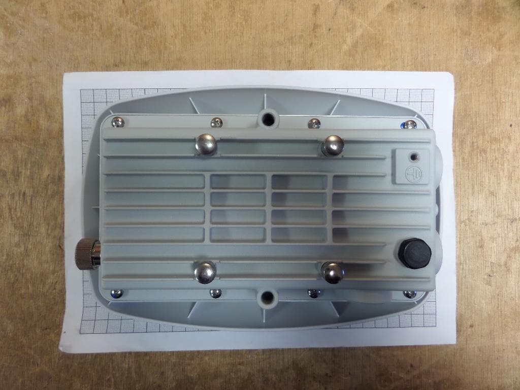
Click to zoom
Application Details
- Equipment Class
- DTS - Digital Transmission System
- Date of Grant
- Mar 01, 2020
- Application Purpose
- Original Equipment
- Date of Application
- Mar 01, 2020
- Equipment Note
- LoRaWAN gateway for the Internet of Things
- Frequency Range
- 923.30000000 - 927.50000000
- Company
- KERLINK SA
- Country
- France
Documents & Files
Document Text
Text extracted from the exhibit documents filed with the FCC. Open a document above to read the original.
Users Manual
Wirnet TM iStation - LoRaWAN® gateway for the Internet of Things Quick Start Guide Thank you for choosing Kerlink. We are proud to be part of your project. Kerlink internal use only For ecological reasons, this guide has been printed on recycled paper 1. Need help? • In order to provide the most updated technical documentation, as well as considering and saving the environmental resources, Kerlink is providing preferably “Online documentation”. • Kerlink is gathering all the technical information on a Wiki: http://wikikerlink.fr/ - If your don’t have yet your Wiki login/password please request them to [email protected] (note that the “Product ID” of one of your products will be required). - How to find the “Product ID”? Please look at the Wirnet iStation sticker placed on the right side of the case. • On the Wiki, Kerlink is proposing a comprehensive set of documents and information for self-help: - Setup of Wirnet™ iStation Gateway: Connection to the gateway, Firmware update, Packet Forwarder installation, Packet Forwarder configuration. - System Management: Connection, login and credentials, KerOS REST API, ... - Network Management: Backhaul configuration, Firewall, IPsec / OpenVPN. - LoRa Features, KerOS customization, Support and resources (FAQ, Troubleshoot the gateway ...) V2.1 | 21.02.2020| Page 1 V2.1 | 21.02.2020|Page 2 • Application Notes: (from end of November 2019) for questions related to generic engineering rules - AN-KLK03355 - Improving radio coexistence performance of LoRaWAN gateways - AN-KLK03356 - LoRaWAN gateways coverage optimization - AN-KLK03357 - LoRaWAN gateways installation recommendations - AN-KLK03358 - LoRaWAN gateways lightning protection • For any Warranty or Maintenance related request (Trouble shooting, help ...), - If purchased from a Distributor, please contact the distributor directly for Level1 support - If purchased from Kerlink directly, please open an “Assistance Request” via our ticketing tool called OTRS (Open-source Ticket Request System) - If you don’t have yet your OTRS login/password, please request them to [email protected] (note that the Product Id or any serial number of one of your products will be required). Access to Kerlink “Technical Support team” for Maintenance Services is conditioned to a valid Maintenance contract. • For any other question related to our product, please contact our distributor or Kerlink [email protected] or + 33 2 99 12 29 00. 2 Manufacturer • Kerlink, 1 Rue Jacqueline Auriol 35235 Thorigné-Fouillard, France Tel.: +33 (0)2 99 12 29 00 – Fax: +33 (0) 2 99 12 29 11 www.kerlink.com 3 Safety • Please, read these instructions carefully and look at the equipment to become familiar with the device before trying to install, operate, or maintain it. • The following special messages may appear throughout this documentation or on the equipment to warn of po- tential hazards or to call attention to information that clarifies or simplifies a procedure. • Refers to a critical situation. • In case of non-compliance, it may result in property damage • Refers to useful information during manipulations. 4 Package Contents • Only use the Wirnet™ iStation for its intended use "Normal conditions of use". • Maintenance and repair must be carried out by qualified personnel authorized by the manufacturer. • The enclosure of the Wirnet™ iStation must not be opened by CUSTOMER . • The Wirnet™ iStation should only be used with accessories or spare parts supplied by your reseller. V2.1 | 21.02.2020 | Page 3 Remarks: • The straps for mounting on a pole are not included, the width should not exceed 14mm. • The screws for mounting on a wall are not included, the diameter of the screws must be 6mm. • The covers have to be screwed at their maximum to ensure waterthightness (USIM and LED/buttons) © Copyright photo - Kerlink - all right reserved 5 Markings SymbolDescriptionSymbolDescription Wirnet iStationType of equipmentQR Code 48V 140mA (PoE) 42-57V 200mA (DC) Power supply information or other marking CE marking indicating that the product complies with current European directives or other marking marking depending on the country Board IDSerial number of board Marking indicating that the product complies with RoHS directives Final product IDSerial number of productDo not dispose of with domestic waste MAC ADDRMAC address Product must be installed on a non- flammable substrate (UL94V0). Refer to the installation instructions Refer to the installation instructions before powering up IP 67Indice of protection V2.1 | 21.02.2020| Page 4 6 Installation of Wirnet™ iStation 6.1 Mounting of the enclosure When installing the product, the ground connection must always be made first. The Wirnet™ iStation enclosure can be mounted on a pole by strapping (see the following example), any concrete pedestal, concrete wall or any non-flammable surface (UL94-V0). Gateway support (Strapping not included) Installation support on a pole with strapping Mandatory ground connection on the Wirnet™ iStation Installation the Wirnet™ iStation on the support V2.1 | 21.02.2020 | Page 5 Before setting all connections, ensure that the power supply is not connected to the mains supply. GNSS, 3G/4G and LoRa antenna are integrated. An external optionnal LoRa antenna can be added by ope- ning the n°3 (please refer on the chart page 3) button and then screw the antenna directly or via a cable. 6.2 Setting connections Ethernet connection Insert Sim Regarding the power supply, the following equipments can be used: • End-Span or Mid-Span at least a 15W PoE (Power over Ethernet) (not included) Once the Wirnet™ iStation is installed, you can select up to 2 technologies to set up the access to Internet for the data backhaul: • Ethernet connection, requiring an Ethernet access through a dedicated RJ45 cable (not included) • 3G/4G cellular connection, requiring an USIM (not included) and a data subscription (not included) Note that both configurations can be used in parallel. For examp…
Text truncated - open the document above for the full version.
Attestation Statements
Date: 02/16/2020 Federal Communications Commission Authorization and Evaluation Division 1435 Oakland Mills Road Columbia, MD 21046 SUBJECT: FCC Application for FCC ID: 2AFYS-KLKWIIS915 To Whom It May Concern: We, the undersigned, hereby attest to the fact that we will apply the supplier Declaration of Conformity procedure to the Class B digital devices portion of this composite filing. Note: We understand that devices subject to the sDoC procedure are required to be tested to show compliance with the FCC technical regulations by a recognized accredited testing laboratory. The testing laboratory must be accredited by a Commission approved accreditation body or designated under the terms of a government-to-government Mutual Recognition Agreement (MRA). A listing of those accredited testing laboratories that have been recognized by the Commission is published on the FCC Webpage: https://apps.fcc.gov/oetcf/eas/reports/TestFirmSearch.cfm Select the "accredited" option to search for FCC recognized accredited test firms. Test facilities located in countries, where the U.S. does not have an operational Telecom MRA are not recognized by the FCC to test for the sDoC procedure. Regards, 02/16/2020 By Yannick DELIBIE President & CEO at KERLINK Inc - Corporate CTIO
ID Label/Location Info
Classification This document is the strict property of Kerlink and shall not be either copied nor sent without express written authorization of Kerlink Internal Use Kerlink communication is everything reserved rights Confidential Kerlink – 1 rue Jacqueline Auriol – 35235 THORIGNÉ-FOUILLARD Page 1 / 3 Strict confidential WIRNET™ ISTATION 915- LABEL LOCALISATION Classification This document is the strict property of Kerlink and shall not be either copied nor sent without express written authorization of Kerlink Internal Use Kerlink communication is everything reserved rights Confidential Kerlink – 1 rue Jacqueline Auriol – 35235 THORIGNÉ-FOUILLARD Page 2 / 3 Strict confidential General view of the Wirnet iStation 915 Classification This document is the strict property of Kerlink and shall not be either copied nor sent without express written authorization of Kerlink Internal Use Kerlink communication is everything reserved rights Confidential Kerlink – 1 rue Jacqueline Auriol – 35235 THORIGNÉ-FOUILLARD Page 3 / 3 Strict confidential Detail of the left side Detail of the sticker 53mm 32mm
Internal Photos
Internal antennas 3dBi external antenna 6dBi external antenna
RF Exposure Info
Siège Social : Emitech - 3, rue des Coudriers - Z.A. de l’Observatoire - 78180 MONTIGNY LE BX - France Siret : 344 545 645 00022 - Tél. : 33 (0)1 30 57 55 55 - Fax : 33 (0)1 30 43 74 48 - E-mail : [email protected] - URL : www.emitech.fr S.A. au capital de 1 560 000 € - R.C.S. VERSAILLES 344 545 645 - APE 7112B RE051-19-105023-1-A Ed. 0 MPE test report According to the standard: CFR 47 FCC PART 15 Equipment under test: Wirnet iStation 915 FCC ID: 2AFYS-KLKWIIS915 Company: KERLINK Distribution: Mr LOUVEAU (Company: KERLINK) Number of pages: 9 with 1 appendix Technical Verification and Quality Approval Ed. Date Modified Page(s) Name and Function Visa 0 24-Jan-20 Creation T. LEDRESSEUR, Radio Technician Duplication of this document is only permitted for an integral photographic facsimile. It includes the number of pages referenced here above. This document is the result of testing a specimen or a sample of the product submitted. It does not imply an assessment of the conformity of the whole manufactured products of the tested sample. RE051-19-105023-1-A Ed. 0 Page 2/9 DESIGNATION OF PRODUCT: Wirnet iStation 915 Serial number (S/N): 1980018353 Reference / model (P/N): Wirnet iStation 915 Software version: V4.2.1 Test software: libloragw-utils_5.0.1-klk10 MANUFACTURER: KERLINK COMPANY SUBMITTING THE PRODUCT: Company: KERLINK Address: 1 Rue Jacqueline Auriol 35235 THORIGNE-FOUILLARD FRANCE Responsible: Mr LOUVEAU DATES OF TEST: From 15-Jan-20 to 24-Jan-20 TESTING LOCATION: EMITECH ANGERS laboratory at JUIGNE SUR LOIRE (49) FRANCE FCC Accredited under US-EU MRA Designation Number: FR0009 Test Firm Registration Number: 873677 TESTED BY: S. LOUIS VISA: WRITTEN BY: S. LOUIS RE051-19-105023-1-A Ed. 0 Page 3/9 CONTENTS TITLE PAGE 1. INTRODUCTION ....................................................................................................................................... 4 2. PRODUCT DESCRIPTION ....................................................................................................................... 4 3. NORMATIVE REFERENCE ...................................................................................................................... 5 4. RF EXPOSURE ......................................................................................................................................... 6 RE051-19-105023-1-A Ed. 0 Page 4/9 1. INTRODUCTION This report presents the results of radio test carried out on the following radio equipment: Wirnet iStation 915, in accordance with normative reference. The device under test integrates the followings radio function: - GPS receiver - 3G/LTE module already certified (FCC ID: XMR201903EG25G) - LoRa function 2. PRODUCT DESCRIPTION Frequencies plan detailed (LoRaWAN standard) Transmitter Channel frequencies LoRa bandwidth (kHz) Number of channel Channel width (kHz) SPREAD FACTOR 923,3+i*0.6MHz (i=0 à 7) 500 8 600 7 to 12 Receiver Channel frenquencies LoRa bandwidth (kHz) Number of channel Channel width (kHz) SPREAD FACTOR 902,3+i*0,2MHz (i= 0 à 63) 125 64 200 7 to 10 903,0+i*1.6MHz (i=0 à 7) 500 8 600 7 to 12 Class: B Utilization: Residential use Antenna type and gain: Internal antenna: 2.6 dBi External antennas: 3 dBi or 6dBi Power source: AC/DC PoE Power level, frequency range and channels characteristics are not user adjustable. The details pictures of the product and the circuit boards are joined with this file. RE051-19-105023-1-A Ed. 0 Page 5/9 3. NORMATIVE REFERENCE The standards and testing methods related throughout this report are those listed below. They are applied on the whole test report even though the extensions (version, date and amendment) are not repeated. CFR 47 FCC Part 15 (2020) Radio Frequency Devices ANSI C63.10 2013 Procedures for ComplianceTesting of Unlicensed Wireless Devices. 447498 D01 General RF RF Exposure procedures and equipment authorization policies for mobile and Exposure Guidance v06 portable equipment OET BULLETIN 65 Evaluating Compliance with FCC Guidelines for Human Exposure to Radiofrequency Electromagnetic Fields RE051-19-105023-1-A Ed. 0 Page 6/9 4. RF EXPOSURE Calculus for LoRa in standalone RF EXPOSURE: The analyze is realized only with the worst critical antenna 6 dBi Maximum measured power = 27.46 dBm at 923.3 MHz With a gain of 6dBi EIRP = 33.46 dBm = 2.2182 W The maximum duty cycle is 40% on the reference period of 6min, so the power computed is: 887.28mW In accordance with KDB 447498 D01 General RF Exposure Guidance v06: PSD= EIRP/(4*π*R 2) 887.28/(4*π*(20 cm)²)= 0.176mW/m² (limit=0.6155 mW/cm2) The MPE ratio is then calculated for the simultaneous transmission. MPE ratio(LoRa) = = 0.286 The equipment fulfils the requirements on power density for general population/uncontrolled exposure and therefore fulfils the requirements of 47 CFR §1.1310. RE051-19-105023-1-A Ed. 0 Page 7/9 Calculus for EG25-G in standalone The results are extracted from EG25-G Module RF Exposure evaluation report referenced HR/2019/1001602 and calculated with the antenna used (see appendix 1). Operating Band Frequency Band (MHz) Frequency (MHz) Conducted Power (dBm) Conducted Power (W) Gain (dBi) Average EIRP (mW) Power density at 20 cm (mW/cm²) Limit (mW/cm²) MPE ratio GSM 850 824-849 824.2 25.81 0.381 -0.7 324.3 0.064 0.55 0.116 GSM 1900 1850-1910 1850.2 22.81 0.191 5.4 662.2 0.132 1 0.132 WCDMA B2 1850-1910 1852.4 25.00 0.316 5.4 1096.5 0.218 1 0.218 WCDMA B4 1710-1755 1712.4 25.00 0.316 5.0 1000 0.199 1 0.199 WCDMA B5 824-849 826.4 25.00 0.316 -0.7 269.2 0.054 0.55 0.098 LTE B2 1850-1910 1850.7 25.00 0.316 5.4 1096.5 0.218 1 0.218 LTE B4 1710-1755 1710.7 25.00 0.316 5.0 1000 0.199 1 0.199 LTE B5 824-849 824.70 25.00 0.316 -0.7 269.2 0.054 0.55 0.098 LTE B7 2500-2570 2502.50 25.00 0.316 6.3 1349 0.268 1 0.268 LTE B12 699-716 699.70 25.00 0.316 -0.7 269.2 0.054 0.47 0.115 LTE B13 777-787 779.50 25.00 0.316 -0.7 269.2 0.054 0.52 0.104 LTE B25 1850-1915 1850.7 25.00 0.316 5.4 1096.5 0.218 1 0.218 LTE B26 814-824 814…
Text truncated - open the document above for the full version.
Test Report
Siège Social : Emitech - 3, rue des Coudriers - Z.A. de l’Observatoire - 78180 MONTIGNY LE BX - France Siret : 344 545 645 00022 - Tél. : 33 (0)1 30 57 55 55 - Fax : 33 (0)1 30 43 74 48 - E-mail : [email protected] - URL : www.emitech.fr S.A. au capital de 1 560 000 € - R.C.S. VERSAILLES 344 545 645 - APE 7112B S 51 RTY 000 INT 00004 [ 0 2 ] LISTE DES SITES ACCREDITES ET PORTEES DISPONIBLES SUR WWW.COFRAC.FR ACCREDITATIONS N° 1-0107, 1-0826, 1-0827, 1- 1925, 1-2069,1-2070, 1-2206, 1-2376 & 1-6086 RR051-19-105023-1-A Ed. 0 Certification Radio test report According to the standard: CFR 47 FCC PART 15 Equipment under test: Wirnet iStation 915 FCC ID: 2AFYS-KLKWIIS915 Company: KERLINK Distribution: Mr LOUVEAU (Company: KERLINK) Number of pages: 67 with 5 appendixes Technical Verification and Quality Approval Ed. Date Modified Page(s) Name and Function Visa 0 24-Jan-20 Creation T. LEDRESSEUR, Radio Technician Duplication of this document is only permitted for an integral photographic facsimile. It includes the number of pages referenced here above. This document is the result of testing a specimen or a sample of the product submitted. It does not imply an assessment of the conformity of the whole manufactured products of the tested sample. RR051-19-105023-1-A Ed. 0 Page 2/67 DESIGNATION OF PRODUCT: Wirnet iStation 915 Serial number (S/N): 1980018353 Reference / model (P/N): Wirnet iStation 915 Software version: V4.2.1 Test software: libloragw-utils_5.0.1-klk10 MANUFACTURER: KERLINK COMPANY SUBMITTING THE PRODUCT: Company: KERLINK Address: 1 Rue Jacqueline Auriol 35235 THORIGNE-FOUILLARD FRANCE Responsible: Mr LOUVEAU DATES OF TEST: From 15-Jan-20 to 24-Jan-20 TESTING LOCATION: EMITECH ANGERS laboratory at JUIGNE SUR LOIRE (49) FRANCE FCC Accredited under US-EU MRA Designation Number: FR0009 Test Firm Registration Number: 873677 TESTED BY: S. LOUIS VISA: WRITTEN BY: S. LOUIS RR051-19-105023-1-A Ed. 0 Page 3/67 CONTENTS TITLE PAGE 1. INTRODUCTION ....................................................................................................................................... 4 2. PRODUCT DESCRIPTION ....................................................................................................................... 4 3. NORMATIVE REFERENCE ...................................................................................................................... 5 4. TEST METHODOLOGY ............................................................................................................................ 5 5. TEST EQUIPMENT CALIBRATION DATES ............................................................................................ 6 6. TESTS RESULTS SUMMARY .................................................................................................................. 7 7. MEASUREMENT UNCERTAINTY ............................................................................................................ 8 8. CONDUCTED LIMITS ............................................................................................................................... 9 9. ADDITIONAL PROVISIONS TO THE GENERAL RADIATED EMISSION LIMITATIONS ......................22 10. MAXIMUM CONDUCTED (AVERAGE) OUTPUT POWER .....................................................................24 11. INTENTIONAL RADIATOR .....................................................................................................................27 12. MAXIMUM CONDUCTED POWER DENSITY .........................................................................................41 APPENDIX 1: TEST EQUIPMENT LIST ........................................................................................................................... 44 APPENDIX 2: 6 DB BANDWIDTH .................................................................................................................................... 46 APPENDIX 3: 99% BANDWIDTH ..................................................................................................................................... 52 APPENDIX 4: BAND EDGE .............................................................................................................................................. 58 APPENDIX 5: SPECTRAL DENSITY ................................................................................................................................ 62 RR051-19-105023-1-A Ed. 0 Page 4/67 1. INTRODUCTION This report presents the results of radio test carried out on the following radio equipment: Wirnet iStation 915, in accordance with normative reference. The device under test integrates the followings radio function: - GPS receiver - 3G/LTE module already certified (FCC ID: XMR201903EG25G) - LoRa function This radio test report concerns only the measure realized on the emission of the LoRa transmitter. 2. PRODUCT DESCRIPTION Frequency band used 902MHz to 928 MHz Frequencies plan detailed (LoRaWAN standard) Transmitter Channel frequencies LoRa bandwidth (kHz) Number of channel Channel width (kHz) SPREAD FACTOR 923,3+i*0.6MHz (i=0 à 7) 500 8 600 7 to 12 Receiver Channel frenquencies LoRa bandwidth (kHz) Number of channel Channel width (kHz) SPREAD FACTOR 902,3+i*0,2MHz (i= 0 à 63) 125 64 200 7 to 10 903,0+i*1.6MHz (i=0 à 7) 500 8 600 7 to 12 Class: B Utilization: Residential use Antenna type and gain: Internal antenna: 2.6 dBi External antennas: 3 dBi or 6dBi Power source: AC/DC PoE Power level, frequency range and channels characteristics are not user adjustable. The details pictures of the product and the circuit boards are joined with this file. RR051-19-105023-1-A Ed. 0 Page 5/67 3. NORMATIVE REFERENCE The standards and testing methods related throughout this report are those listed below. They are applied on the whole test report even though the extensions (version, date and amendment) are not repeated. CFR 47 FCC Part 15 (2020) Radio Frequency Devices ANSI C63.10 2013 Procedures for ComplianceTesting of Unlic…
Text truncated - open the document above for the full version.
Test Setup Photos
Anechoic chamber setup Above 1 GHz 1: Equipment Under Test 2: Measurement antenna 3: Measurement equipment 1 2 1.5 m 3 Distance : 3 m 1.5 m Turntable Installation of Equipment Under Test Internal antenna 3dBi external antenna 6dBi external antenna Anechoic chamber test site Pre-measure below 30 MHz Pre-measure between 30 MHz to 200 MHz Pre-measure between 200 MHz to 1000 MHz Measure between 1 GHz to 18 GHz Conducted measurement setup Internal antenna 3dBi external antenna 6dBi external antenna
Contact Information
Applicant
YANNICK DELIBIE
Test Firm
EMITECH AngersMounir El Marzouki
Technical Specifications
| # | Rule Parts | Frequency Range | Power Output |
|---|---|---|---|
| 1 | 15C | 923.3 MHz - 927.5 MHz | 557.00 mW |
Other Applications from KERLINK SA
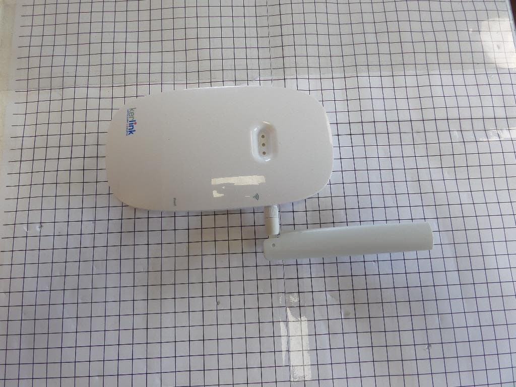
2AFYS-KLK915MWIFC
Jul 11, 2021The Wirnet iFemtoCell is an indoor LoRa Gateway for IoT chain.
Equipment Class
DTS - Digital Transmission System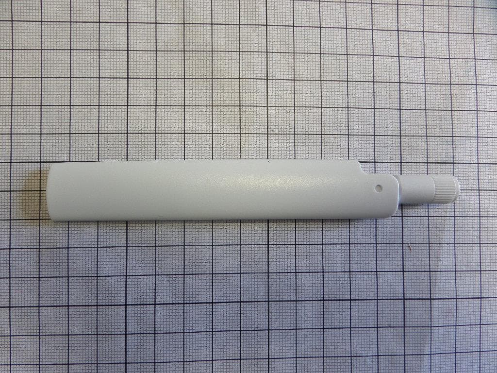
2AFYS-KLKFEVO915
Mar 22, 2020LoRaWAN gateway for the Internet of Things
Equipment Class
DTS - Digital Transmission System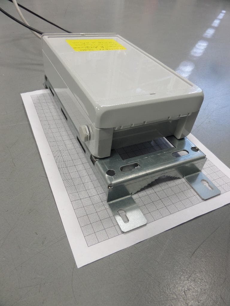
2AFYS-KLK915LOI
Nov 02, 2015Tele transmission
Equipment Class
DTS - Digital Transmission System