2AG2K-BV-001TXWireless remote control vibrator
A&H Design Group, Ltd.
Click to zoom
Application Details
- Equipment Class
- DSC - Part 15 Security/Remote Control Transmitter
- Date of Grant
- Jan 04, 2016
- Application Purpose
- Original Equipment
- Date of Application
- Jan 04, 2016
- Equipment Note
- Wireless remote control vibrator
- Frequency Range
- 433.92000000 - 433.92000000
- Company
- A&H Design Group, Ltd.
- Country
- China
Documents & Files
Document Text
Text extracted from the exhibit documents filed with the FCC. Open a document above to read the original.
Users Manual
23 OVERVIEW b-Vibe TM products are made with silky smooth, body- safe silicone. Our products are phthalate-free and latex-free. The easy to use interface allows users to easily reach your desired stimulation and intensity level. Get ready for sensual satisfaction that can not be matched and will have you craving for more. b-Vibe TM Rimming Plug 45 Internal Stimulator Rimming Beads Base Control Button Magnetic Charging Contact LED Indicator Decrease Intensity/ Rotation speed Power Button Vibration Function Button Rotation Button Increase Intensity/ Rotation speed RIMMING PLUGWIRELESS REMOTE CONTROL 7 GETTING STARTED 1. Before first use, charge your plug for approximately 2 hours. The USB charging cable can be plugged into any USB port or USB/AC power adapter (not included) • Flashing Light = Charging • Solid Light = Fully Charged • Rapid Flashing Light = Low battery, charge is needed 2. Wash your plug with soap and water, or toy cleaner suitable for use with silicone items. FAQs can be found at www.bvibe.com Email us at [email protected] for any unanswered questions 3. Lubricate your plug with a water based, silicone compatible lubricant. 4. Turn ON your plug by pressing quickly at the bottom of your plug. The light will flash, indiciating the power is on and in standby mode. Push again to use the manual mode, or push on the remote to pair the remote & plug. Once in use, the base light will change from flashing to solid. TOY CLEANER LUBE 89 5. To change the vibration intensity and/or rotation speed via the base control, press the A .To change the vibration intensity and/or rotation speed via the remote control press and release the A and the A 5. To change the vibration intensity and/or rotation speed via the remote control press and release A (Increase Intensity/Rotation speed)and A (Decrease Intensity/Rotation speed) 1. To turn the item ON quickly press The will flash to indicate the power is on. Push again to change the vibration pattern. There are a total of 8 modes using the manual control. 2. To power OFF your plug press and hold for 2 seconds. LED will turn off to indicate the power is OFF. MANUAL CONTROL 1 2 1011 1. First turn your plug on in standby mode by quickly pressing on your plug. 2. While the baselight is flashing, power on your remote to pair the remote & plug. 3. Once the item is paired the base light will become solid and you can control your plug by remote. 4. Press and release to increase vibration intensity and/or rotation speed. 5. Press and release to decrease vibration intensity and/or rotation speed 6. To change the independent vibration mode in the top press and release 7. Holding or for 3 seconds will turn off the independent shaft vibrator and/or rimming beads. 8. Holding or for 3 seconds will turn on the independent shaft vibrator and/or rimming beads. 9. To turn the item ON/OFF press and release on the remote 10. To completely turn off your plug, press and hold on your plug. REMOTE CONTROL 1213 CHARGING YOUR PLUGCHANGING YOUR REMOTE CONTROL BATTERY • Attach the magnetic charging plug to the designated charging area on the base of the product • Flashing light indicates item is charging • Solid light indicates item is fully charged • Plugs require approximately 2.5 hours for full charge • Slide open the remote control battery compartment as shown. • Button cell CR 2032 has been preinstalled into the remote control. • Remove the paper slip inside the battery compartment to activate the power in the remote control. • Suggested to remove the battery from the remote control for extended stroage. Store the remote control and the battery seperately. Flashing light = Charging Solid light = Fully Charged OPEN 1415 TRAVEL LOCK • All b-Vibe items include travel lock for safe and convenient travel For the remote: Simultaneously press and hold the and buttons for 3 seconds. Flashing light will indicate the item is locked. To unlock simply press and hold and again for 3 seconds. Flashing light will indicate lock is disabled. For the plug: Hold for 5 seconds, flashing light will indicate the item is locked. For unlocking, hold again for 5 seconds, flashing light will indicate the item is unlocked. 1 2 3 1 2 3 4 5 15 VIBRATING MODES Internal Stimulator Rimming Beads 1. Low Vibration 2. Medium Vibration 5. Wave 4. Maximum Vibration 3. High Vibration 6. Pulse 7. Ascend 8. Oscillate 9. Random 1. Low 2. Speed II 3. Speed III 4. Speed IV 5. Speed V 6. Speed VI 7. Speed VII 8. Speed VIII 9. Maximum 1617 1. Always clean your plug thoroughly before and after each use. 2. We recommend premium water- based lubricant. Silicone-based lubricants are not recommended and can cause damage to the product. 3. To properly clean your plug, wash with luke-warm water and a respected antibacterial soap. Rinse clean and pat dry using a lint-free cloth or towel. Do not use cleaners containing alcohol, petrol or acetone. 4. Avoid leaving your plug in direct sunlight and never expose it to extreme heat. 5. Our products are designed to be water submersable and are safe to immerse in water. If your plug appears to function abnormally, turn OFF and consult our customer care section on bvibe.com, where you will find help tips. Should you require further assistance please contact: [email protected] b-Vibe Care Cleaning, Storage & Safety TOY CLEANER LUBE 1819 Materials Size Weight Battery Charging Use Time Max Noise Level Interface Body Safe Silicone/ ABS 151 x 79 x 41 mm 197 g Battery li-ion 550m-Ah 1.5 hours 1.5 hours < 68 dB Single Button Manual Control 5 Button Remote Control SPECIFICATIONS The crossed-out dustbin symbol indicates that these items should not be treated as household waste, but rather brought to the appropriate collection point for recycling electrical and electronic equipment. DISPOSAL INFORMATION Disposal of old electronic equipment (applicable in the EU and other European countries with separate waste collection systems): 2021 Declaration of Conformity Hereby, b-Vibe d…
Text truncated - open the document above for the full version.
Cover Letter(s)
SCS-F18: Project and Product Certification Representative Authorization Letter Page 1 of 2 Rev 5.0 775 Montague Expressway Milpitas, CA 95035 Tel: 408-526-1188 Fax: 408-526-1088 Email: [email protected] Project and Product Certification Representative Authorization Letter Reason for Amendment (current / obsolete) Revision History Approved Date From To Initial Release (obsolete) 1.0 1.0 Nov-14-2006 Revised wording (obsolete) 1.0 2.0 Sept–25-2007 Updated company template (obsolete) 2.0 3.0 Jan-31-2012 Updated letter information (obsolete) 3.0 4.0 May-23-2014 Added FCC ID field (current) 4.0 5.0 Sept 16 2014 SCS-F18: Project and Product Certification Representative Authorization Letter Page 2 of 2 Rev 5.0 A&H Design Group, Ltd. Dec 20, 2015 To: SIEMIC, INC. 775 Montague Expressway, Milpitas, CA 95035 USA Dear Sir/Madam, Re: Product Certification Representative Authorization Letter We, A&H Design Group, Ltd. hereby authorize SIEMIC, Inc. to act as a Certification Body for certifying for the following project(s): Product name: Wireless remote control vibrator Model No.: BV-001 BLK, BV-001 TL FCC ID:2AG2K-BV-001TX Sincerely, Client’s signature Client’s name / title : Charlotte Tang / Manager Contact address: Suite 608, Tower One, Harbour Centre1 Hok Cheung Street, Hung Hom ,Kowloon, Hong Kong Contact telephone: 00852-23677768 Email: [email protected]
Cover Letter(s)
SCS-F19: Confidentiality Request Letter Page 1 of 2 Rev 5.0 775 Montague Expressway Milpitas, CA 95035 Tel: 408-526-1188 Fax: 408-526-1088 Email: [email protected] Confidentiality Request Letter Reason for Amendment (current / obsolete) Revision History Approved Date From To Initial Release (obsolete) 1.0 1.0 Nov-14-2006 Adding CFR 2.459 (obsolete) 1.0 2.0 August – 11 - 2008 Updated company template & Added text box (obsolete) 2.0 3.0 Jan-31-2012 Added IC confidentiality letter form (obsolete) 3.0 4.0 March-26-2015 Corrections to STC form. Added reference to KDB (current) 4.0 5.0 Nov 19 2015 SCS-F19: Confidentiality Request Letter Page 2 of 2 Rev 5.0 A&H Design Group, Ltd. Dec 20, 2015 To: Federal Communications Commission Authorization and Evaluation Division 7435 Oakland Mills Road Columbia, MD Subject: Permanent Confidentiality Request for FCC ID: 2AG2K-BV-001TX Pursuant to sections 0.457 and 0.459 of CFR 47, we respectfully request permanent confidential treatment of the following Exhibits accompanying this application as: - Block Diagram - Schematics - Operational Description The above materials contain trade secrets and proprietary information not customarily released to the public. The public disclosure of these materials may be harmful to the applicant and provide unjustified benefits to its competitors. The applicant understands that disclosure of this application and all accompanying documentation will not be made before the date of the Grant for this application. Sincerely, Client’s signature Client’s name / title : Charlotte Tang / Manager Contact address: Suite 608, Tower One, Harbour Centre1 Hok Cheung Street, Hung Hom ,Kowloon, Hong Kong Contact telephone: 00852-23677768 Email: [email protected]
Cover Letter(s)
A&H Design Group, Ltd. Date: Dec 20, 2015 FCC ID: 2AG2K-BV-001TX Statement Product name: Wireless remote control vibrator Model No.: BV-001 BLK, BV-001 TL FCC ID: 2AG2K-BV-001TX We hereby state that these models are identical in interior structure, electrical circuits and components, Product model is different because of different Color of product appearance. Your assistance on this matter is highly appreciated. Sincerely, Client’s signature Client’s name / title : Charlotte Tang / Manager Contact address: Suite 608, Tower One, Harbour Centre1 Hok Cheung Street, Hung Hom ,Kowloon, Hong Kong Contact telephone: 00852-23677768 Email: [email protected]
External Photos
External Photos Model: BV-001 BLK Model: BV-001 TL
ID Label/Location Info
Label and label location Model No.: BV-001 BLK FCC ID: 2AG2K‐BV‐001TX Rated: 3V (Use CR2032 Button cell 1× ) Frequency: 433.92MHz TOPARC Technology(Shenzhen) Co., Ltd. Model No.: BV‐001 TL FCC ID: 2AG2K‐BV‐001TX Rated: 3V (Use CR2032 Button cell 1× ) Frequency: 433.92MHz TOPARC Technology(Shenzhen) Co., Ltd.
Internal Photos
Internal Photos Antenna
Test Report
Report No.: ATE20152702 Page 1 of 28 FCC ID: 2AG2K-BV-001TX ACCURATE TECHNOLOGY CO., LTD APPLICATION CERTIFICATION On Behalf of A&H Design Group, Ltd. Wireless remote control vibrator Model No.: BV-001 BLK, BV-001 TL FCC ID: 2AG2K-BV-001TX Prepared for : A&H Design Group, Ltd. Address : Suite 608, Tower One, Harbour Centre1 Hok Cheung Street, Hung Hom ,Kowloon, Hong Kong Prepared by : ACCURATE TECHNOLOGY CO., LTD Address : F1, Bldg. A, Changyuan New Material Port, Keyuan Rd. Science & Industry Park, Nanshan, Shenzhen, Guangdong P.R. China Tel: (0755) 26503290 Fax: (0755) 26503396 Report Number : ATE20152702 Date of Test : Dec 21-24, 2015 Date of Report : Dec 24,2015 Report No.: ATE20152702 Page 2 of 28 FCC ID: 2AG2K-BV-001TX ACCURATE TECHNOLOGY CO., LTD TABLE OF CONTENTS Description Page Test Report Certification 1. GENERAL INFORMATION .......................................................................................................... 4 1.1. Description of Device (EUT) .................................................................................................................... 4 1.2. Description of Test Facility ...................................................................................................................... 5 1.3. Measurement Uncertainty ......................................................................................................................... 5 2. MEASURING DEVICE AND TEST EQUIPMENT ..................................................................... 6 3. SUMMARY OF TEST RESULTS ................................................................................................... 7 4. THE FIELD STRENGTH OF RADIATION EMISSION ............................................................ 8 4.1. Block Diagram of Test Setup .................................................................................................................... 8 4.2. The Field Strength of Radiation Emission Measurement Limits .............................................................. 9 4.3. Configuration of EUT on Measurement ................................................................................................... 9 4.4. Operating Condition of EUT .................................................................................................................... 9 4.5. Test Procedure ........................................................................................................................................ 10 4.6. The Field Strength of Radiation Emission Measurement Results .......................................................... 11 5. 20DB OCCUPIED BANDWIDTH ................................................................................................ 13 5.1. Block Diagram of Test Setup .................................................................................................................. 13 5.2. The Bandwidth of Emission Limit According To FCC Part 15 Section 15.231(c) ................................ 13 5.3. EUT Configuration on Measurement ..................................................................................................... 14 5.4. Operating Condition of EUT .................................................................................................................. 14 5.5. Test Procedure ........................................................................................................................................ 14 5.6. Measurement Result ............................................................................................................................... 14 6. RELEASE TIME MEASUREMENT ............................................................................................ 15 6.1. Block Diagram of Test Setup .................................................................................................................. 15 6.2. Release Time Measurement According To FCC Part 15 Section 15.231(a) .......................................... 15 6.3. EUT Configuration on Measurement ..................................................................................................... 16 6.4. Operating Condition of EUT .................................................................................................................. 16 6.5. Test Procedure ........................................................................................................................................ 16 6.6. Measurement Result ............................................................................................................................... 16 7. AVERAGE FACTOR MEASUREMENT .................................................................................... 17 7.1. Block Diagram of Test Setup .................................................................................................................. 17 7.2. Average factor Measurement according to ANSI C63.10-2013 ............................................................. 17 7.3. EUT Configuration on Measurement ..................................................................................................... 18 7.4. Operating Condition of EUT .................................................................................................................. 18 7.5. Test Procedure ........................................................................................................................................ 18 7.6. Measurement Result ............................................................................................................................... 18 8. ANTENNA REQUIREMENT........................................................................................................ 19 8.1. The Requirement .................................................................................................................................... 19 8.2. Antenna Construction ...................................................…
Text truncated - open the document above for the full version.
Test Setup Photos
Test photo
Contact Information
Applicant
Thomas Cheung(Manager)
Test Firm
Accurate Technology Co., Ltd.Sean Liu
Technical Specifications
| # | Rule Parts | Frequency Range | Power Output |
|---|---|---|---|
| 1 | 15.231 | 433.92 MHz - 433.92 MHz | - |
Other Applications from A&H Design Group, Ltd.
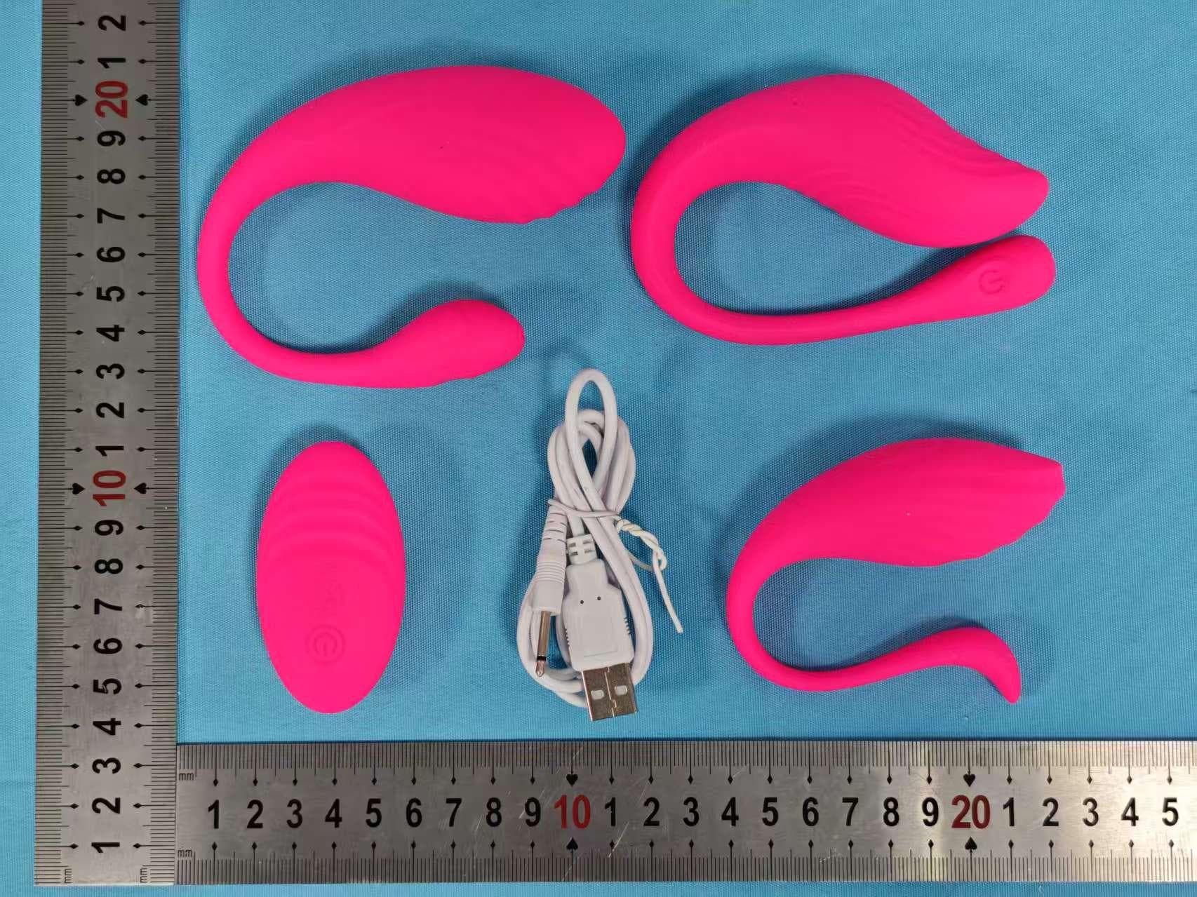
2AG2K-TOG-025
Mar 12, 2026Rechargeable remote (MENAGE A TROIS REMOTE CONTROL ORGY EGG SET)
Equipment Class
DSC - Part 15 Security/Remote Control Transmitter
2AG2K-CG-017
Jan 24, 2026Cowgirl Saddle Machine
Equipment Class
DSC - Part 15 Security/Remote Control Transmitter
2AG2K-CG-018
Jan 24, 2026Cowgirl Grinding Vibrating & Tapping
Equipment Class
DSC - Part 15 Security/Remote Control Transmitter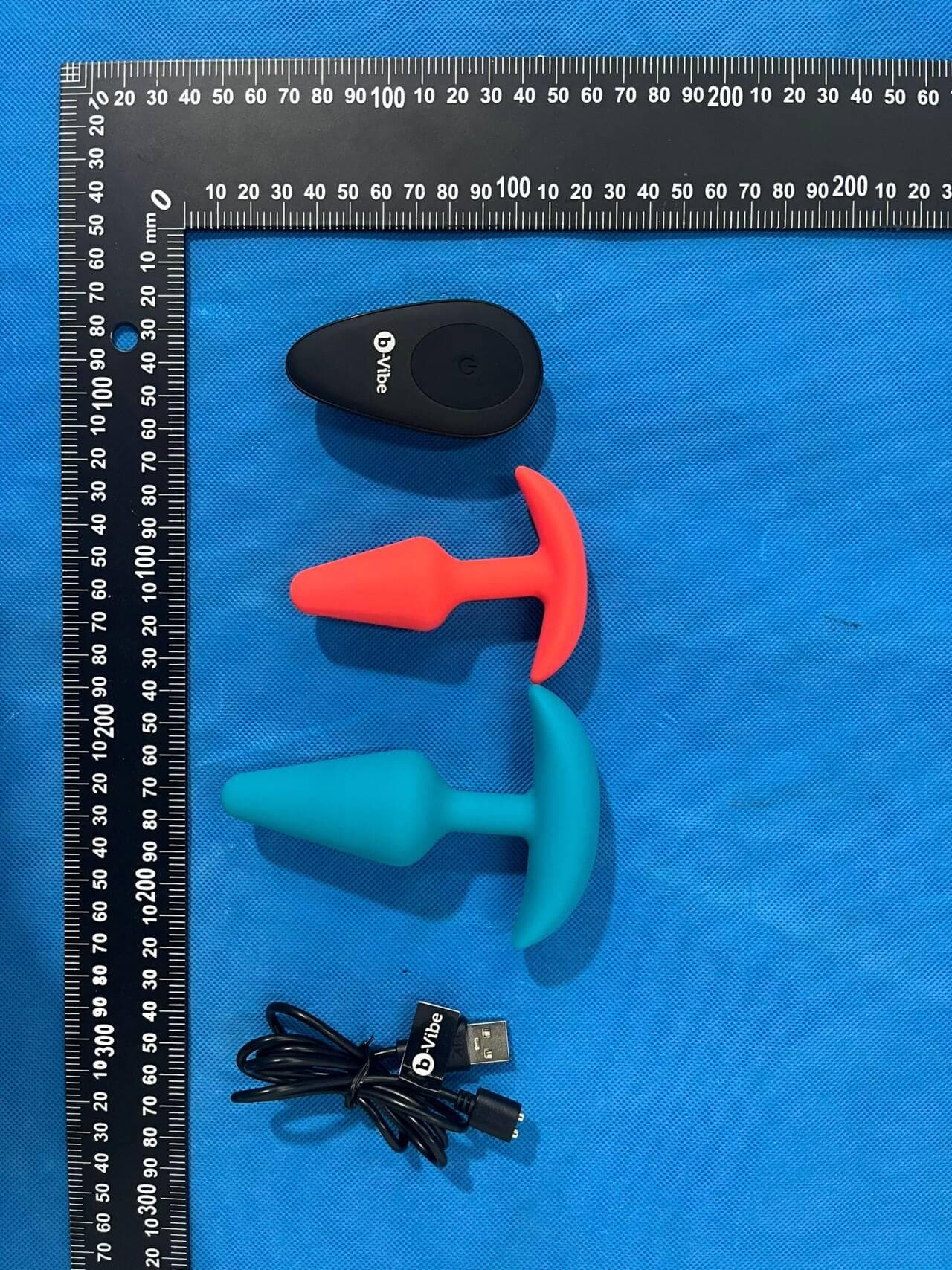
2AG2K-AHBVR03
Dec 25, 2025Anal Training Bundle
Equipment Class
DSC - Part 15 Security/Remote Control Transmitter2AG2K-OUT265
Sep 25, 2024Remote control layon vibe
Equipment Class
DSC - Part 15 Security/Remote Control Transmitter