2AG7C-BULLET8-A5IP CAMERA
Hangzhou Meari Technology Co., Ltd.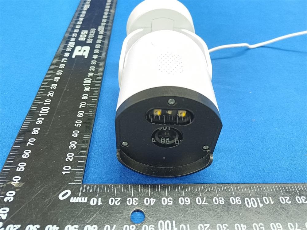
Click to zoom
Application Details
- Equipment Class
- DTS - Digital Transmission System
- Date of Grant
- Aug 26, 2021
- Application Purpose
- Original Equipment
- Date of Application
- Aug 26, 2021
- Equipment Note
- IP CAMERA
- Frequency Range
- 2412.00000000 - 2462.00000000
- Country
- China
Documents & Files
Document Text
Text extracted from the exhibit documents filed with the FCC. Open a document above to read the original.
Users Manual
QUICK GUIDE ORIGINALITY DESIGN SMART - AND BEAUTIFUL Bullet 8S Consult the checklist below for all components. 1 Camera Manual Power adapter Screw package Screwdriver What's in the box 2 Status light Speaker Reset Microphone SD card slot Power Status light DC12±10% Blinking red light: wait for network connection Solid blue light on: camera is working correctly Solid red light on: camera is malfunctional Capture sound for your video Support local SD Card storage (Max.128 GB) Press and hold for 5 seconds to reset the camera (if you have modified settings, they will return to factory defaults) Microphone SD card slot Reset Description 3 Bracket Installation Installation 1. Push the bracket in the direction shown to take apart. 2. Install the bracket to the wall with screws. Put the UP logo up. 3. Insert the bracket upward and then push the bracket in the opposite direction of step 1, to lock the bracket with the camera. (Optional) You can adjust the camera horizontally or vertically by manual. It is recommended to adjust camera horizontally between 0 to 150 degrees, and vertically between 15 to 20 degrees. You can also rotate the bracket from 0 to 360 degrees. 1 2 3 0°~360° 0°~150° Recommend 15°~20° 4 Set up router The router supports the 2.4GHz Wi-Fi (doesn't support the 5GHz), and is connected to the Wi-Fi network. Please set the parameters of the router before connecting the Wi-Fi network, and record the SSID and password of your Wi-Fi. Please keep network available 2.4GHz5GHz Download SmartLife or Tuya Smart is available for both iOS and Android OS. Search the name 'SmartLife','Tuya Smart' in App Store or Google Play, or scan the QR- Code to download the App. You can select the App according to needs. iPadAndroidiOS ·Support Download App(iOS&Android) Connection 5 Connection Registration process Step 1 Step 2 Input a legal and valid Mobile number or Email address and click "Get Verification Code". Input the verification code to log in. Open the Smart Life App, click "Sign Up", read the "User Agreement Privacy Policy" and click "Agree" . 6 QR Code Configuration Open the Smart Life App, click "My" >> "Home Management" >> "Create a home", and you can customize the home name and related settings. 1 Click "Add Device" or "+", and then select "Security & Sensor" >> "Smart Camera" to add camera. 2 7 QR Code Configuration Power on and reset camera until the status indicator is flashing quickly or a prompt tone is heard, and then click "Next". Then input your Wi-Fi's passwords and click "Next". Click " " to change network. 3 Note: 1) Camera only supports 2.4GHz Wi-Fi network. 2) The number of bits in the SSID and passwords of the router should not exceed 24 digits. 8 QR Code Configuration In this interface, you should scan the QR code in your phone with the camera,when the camera comes out "dong dong dong". And you can complete the configuration about 30s. 4 9 QR Code Configuration When connecting, you should make sure your router,mobile,and camera are as close as possible. When camera added successfully,click " " you could also DIY the camera's name. 5 10 Settings In "Smart Camera" interface,click " ",you can set the camera common functions. 11 Q: Why is it still in the list of devices after reseting? A: The reset device only resets the network configuration of the camera, but cannot change the configuration on the App, remove the camera, and must be deleted by the App. Q: How to cut the camera network to another router? A: First remove and reset the device on the App and then configure the device again by the App. Q: Why doesn't the device identify the SD card? A: It is recommended to plug in SD card after power cut. Confirm whether the SD card is normally available and the format is FAT32. And the TF card can't be identified when the Internet environment is not good. Q: Why I can't get the notifications with my cell phone App? A: Please confirm that the App has been running on the phone, and the relevant reminder function has been opened;Message notification and authority confirmation in the mobile phone system have been opened. Q: The device cannot be previewed properly? A: Check whether the network is normal, you can place the camera close to the router, and if not, it is recommended to reset the device and add it again. FAQ Functions 12 DaytimeNight Video flip Flip your video stream up or down for maximum flexibility. Motion detection Support smart motion detection. The camera will detect movements, and then send you push notifications and app alerts. Record Support 24H continuous recording with high capacity SD storage or Cloud storage. Day & Night Never miss a moment, even in complete darkness, with powerful night-vision technology. 13 Functions FCC Statement This equipment has been tested and found to comply with the limits for a Class B digital device, pursuant to part 15 of the FCC Rules. These limits are designed to provide reasonable protection against harmful interference in a residential installation. This equipment generates, uses and can radiate radio frequency energy and, if not installed and used in accordance with the instructions, may cause harmful interference to radio communications. However, there is no guarantee that interference will not occur in a particular installation. If this equipment does cause harmful interference to radio or television reception, which can be determined by turning the equipment off and on, the user is encouraged to try to correct the interference by one or more of the following measures: —Reorient or relocate the receiving antenna. —Increase the separation between the equipment and receiver. —Connect the equipment into an outlet on a circuit different from that to which the receiver is connected. —Consult the dealer or an experienced radio/TV technician for help. FCC Radiation Exposure Statement This device complies with FCC radiation exposure limits set forth for an uncontrolled environment and it also complies with Part 15 of the FCC RF Rules.…
Text truncated - open the document above for the full version.
Cover Letter(s)
ModelDeclarationLetter We,theundersigningcompany CompanyName:HangzhouMeariTechnologyCo.,Ltd. Address:Room604-605,Building1,No.768JianghongRoad,Changhestreet,Binjiang District,Hangzhou,zhejiang,China Herebyconfirmthatthefollowingproducts: Product description:IP CAMERA Type designation:Bullet 8S,Bullet 8T,Bullet 8Q,Bullet 11S,Bullet 11T,Bullet 11Q That The PCB board, structure and internal of these model(s) above are the same, Only the model name is different. There are two versions of the EUT, only differ in the main control of IC, one is AK3918EV300, the other is AK3918EV330L, the main function of this IC is video modulation and decoding,the others are the same . Date: 2021-8-25 Name: Zhiyang Chai Telephone: +8615869048127 E-mail: [email protected] Signature:
Cover Letter(s)
Confidentiality Request Letter For Certification Service in the USA FederalCommunicationCommission EquipmentAuthorizationDivision,ApplicationProcessingBranch 7435OaklandMillsRoad Columbia,MD21048 Towhomitmayconcern PursuanttoParagraphs§0.457and0.459oftheCommission’sRules(47C.F.R.)andSection §552(b)(4)oftheFreedomofInformationAct,werequestconfidentialityforthe documentationofthefollowingproducts: FCCIDModelname 2AG7C-BULLET8-A5Bullet 8S,Bullet 8T,Bullet 8Q,Bullet 11S, Bullet 11T,Bullet 11Q Fortheproductslistedabove,werequestpermanentconfidentialityforallapplicable exhibitsasthereare: theOperationalDescription theBlockDiagram theSchematics Theabovelistedexhibitscontaintradesecretsandproprietaryinformationthatcouldbeof benefittoourcompetitors. Ifyouhaveanyquestions,pleasefeelfreetocontactusattheaddressshownbelow. Sincerely, 2021-8-25 Signature Date PrintedNameofSignee: Company:HangzhouMeariTechnologyCo.,Ltd. Address: Room604-605,Building1,No.768JianghongRoad,Changhestreet,Binjiang District,Hangzhou,zhejiang , China Phone: +8615869048127 Email:[email protected]
External Photos
Report No.: GTS20210806010-1-11 Page 43 of 60 6. E X T E R N A L A N D I N T E R N A L P H O T O S O F T H E EUT Fig. 1 Fig. 2 Version A Version B Report No.: GTS20210806010-1-11 Page 44 of 60 Fig. 3 Fig. 4 Report No.: GTS20210806010-1-11 Page 45 of 60 Fig. 5 Fig. 6 Report No.: GTS20210806010-1-11 Page 46 of 60 Fig. 7 Fig. 8 Report No.: GTS20210806010-1-11 Page 47 of 60 Fig. 9 Fig. 10 Report No.: GTS20210806010-1-11 Page 48 of 60 Fig. 11 Fig. 12 Report No.: GTS20210806010-1-11 Page 49 of 60 Fig. 13 Fig. 14 Report No.: GTS20210806010-1-11 Page 50 of 60 Fig. 15 Fig. 16
ID Label/Location Info
Labellocation
Internal Photos
Report No.: GTS20210806010-1-11 Page 50 of 60 Fig. 15 Fig. 16 Report No.: GTS20210806010-1-11 Page 51 of 60 Fig. 17 Fig. 18 Report No.: GTS20210806010-1-11 Page 52 of 60 Fig. 19 Fig. 20 Report No.: GTS20210806010-1-11 Page 53 of 60 Fig. 21 Fig. 22 Report No.: GTS20210806010-1-11 Page 54 of 60 Fig. 23 Fig. 24 Report No.: GTS20210806010-1-11 Page 55 of 60 Fig. 25 Fig. 26 Antenna Report No.: GTS20210806010-1-11 Page 56 of 60 Fig. 27 Fig. 28 Report No.: GTS20210806010-1-11 Page 57 of 60 Fig. 29 Fig. 30 Report No.: GTS20210806010-1-11 Page 58 of 60 Fig. 31 Fig. 32 Report No.: GTS20210806010-1-11 Page 59 of 60 Fig. 33 Fig. 34 Report No.: GTS20210806010-1-11 Page 60 of 60 Fig. 35 Fig. 36 .......................End of Report........................
Test Report
Shenzhen Global Test Service Co.,Ltd. No.7-101 and 8A-104, Building 7 and 8, DCC Cultural and Creative Garden, No.98, Pingxin North Road, Shangmugu Community, Pinghu Street, Longgang District, Shenzhen, Guangdong RF Exposure evaluation Report Reference No...................... : FCC ID. ............................................ : GTS20210806010-1-12 2AG7C-BULLET8-A5 Compiled by ( position+printed name+signature) . : File administrators Peter Xiao Supervised by ( position+printed name+signature) . : Test Engineer Oliver Ou Approved by ( position+printed name+signature) . : Manager Simon Hu Date of issue .................................... : Aug.18, 2021 Representative Laboratory Name . : Shenzhen Global Test Service Co.,Ltd. Address ............................................ : No.7-101 and 8A-104, Building 7 and 8, DCC Cultural and Creative Garden, No.98, Pingxin North Road, Shangmugu Community, Pinghu Street, Longgang District, Shenzhen, Guangdong Applicant’s name ............................ : Hangzhou Meari Technology Co., Ltd. Address ............................................ : Room 604-605, Building 1, No.768 Jianghong Road, Changhe street, Binjiang District, Hangzhou, zhejiang, China Test specification ........................... : Standard ........................................... : 47CFR §1.1310 47CFR §2.1091 KDB447498 D01 General RF Exposure Guidance v06 TRF Originator .................................. : Shenzhen Global Test Service Co.,Ltd. Master TRF ...................................... : Dated 2014-12 Shenzhen Global Test Service Co.,Ltd. All rights reserved. This publication may be reproduced in whole or in part for non-commercial purposes as long as the Shenzhen Global Test Service Co.,Ltd. is acknowledged as copyright owner and source of the material. Shenzhen Global Test Service Co.,Ltd. takes no responsibility for and will not assume liability for damages resulting from the reader's interpretation of the reproduced material due to its placement and context. Test item description ..................... : IP CAMERA Trade Mark ....................................... : N/A Manufacturer .................................... : Hangzhou Meari Technology Co., Ltd. Model/Type reference ...................... : Bullet 8S Listed Models .................................. : Bullet 8T, Bullet 8Q, Bullet 11S, Bullet 11T, Bullet 11Q Modulation Type ............................... : 802.11b: DSSS; 802.11g/n: OFDM Operation Frequency........................ : From 2412MHz to 2462MHz Hardware Version ............................ : 38X38-A5MB-GC1 REV1_0(Version A) 38X38-A2MB-GC2063 REV1_1(Version B) Software Version .............................. : N/A Rating ............................................... : DC 12.0V/1.0A by Adapter Result ............................................... : PASS Report No.: GTS20210806010-1-12 Page 2 of 12 T E S T R E P O R T Test Report No. : GTS20210806010-1-12 Aug.18, 2021 ______________________________________________________________________________________________ Date of issue Equipment under Test : IP CAMERA Model /Type : Bullet 8S Listed model : Bullet 8T, Bullet 8Q, Bullet 11S, Bullet 11T, Bullet 11Q Applicant : Hangzhou Meari Technology Co., Ltd. Address : Room 604-605, Building 1, No.768 Jianghong Road, Changhe street, Binjiang District, Hangzhou, zhejiang, China Manufacturer : Hangzhou Meari Technology Co., Ltd. Address : No. 91 Chutian Road, Xixing Street, Binjiang District, Hangzhou, Zhejiang, China Test Result: PASS The test report merely corresponds to the test sample. It is not permitted to copy extracts of these test result without the written permission of the test laboratory. Report No.: GTS20210806010-1-12 Page 3 of 12 Contents 1. SUMMARY ................................................................................................................................................................. 4 1.1 EUT CONFIGURATION ........................................................................................................................................................ 4 1.2 PRODUCT DESCRIPTION ..................................................................................................................................................... 4 1.3 DIFFERENCE DESCRIPTION ................................................................................................................................................... 5 2. TEST ENVIRONMENT ................................................................................................................................................. 6 2.1 ADDRESS OF THE TEST LABORATORY ..................................................................................................................................... 6 2.2 TEST FACILITY .................................................................................................................................................................. 6 2.3 ENVIRONMENTAL CONDITIONS ............................................................................................................................................ 6 2.4 STATEMENT OF THE MEASUREMENT UNCERTAINTY .................................................................................................................. 6 3. METHOD OF MEASUREMENT .................................................................................................................................... 7 3.1 APPLICABLE STANDARD ...................................................................................................................................................... 7 3.2 REQUIREMENT ................................................................................................................................................................. 7 3.3 LIMIT ...........................................................................................................................................................…
Text truncated - open the document above for the full version.
Test Report
Shenzhen Global Test Service Co.,Ltd. No.7-101 and 8A-104, Building 7 and 8, DCC Cultural and Creative Garden, No.98, Pingxin North Road, Shangmugu Community, Pinghu Street, Longgang District, Shenzhen, Guangdong FCC PART 15 SUBPART C TEST REPORT FCC PART 15.247 Report Reference No. .....................: FCC ID. ............................................ : GTS20210806010-1-11 2AG7C-BULLET8-A5 Compiled by ( position+printed name+signature) .. : File administrators Peter Xiao Supervised by ( position+printed name+signature) .. : Test Engineer Oliver Ou Approved by ( position+printed name+signature) .. : Manager Simon Hu Date of issue ..................................... : Aug.18, 2021 Representative Laboratory Name .: Shenzhen Global Test Service Co.,Ltd. Address ............................................ : No.7-101 and 8A-104, Building 7 and 8, DCC Cultural and Creative Garden, No.98, Pingxin North Road, Shangmugu Community, Pinghu Street, Longgang District, Shenzhen, Guangdong,China Applicant’s name ............................ : Hangzhou Meari Technology Co., Ltd. Address ............................................ : Room 604-605, Building 1, No.768 Jianghong Road, Changhe street, Binjiang District, Hangzhou, zhejiang, China Test specification ...........................: Standard ........................................... : FCC Part 15.247: Operation within the bands 902-928 MHz, 2400- 2483.5 MHz and 5725-5850 MHz ANSI C63.10-2013 TRF Originator .................................. : Shenzhen Global Test Service Co.,Ltd. Master TRF ....................................... : Dated 2014-12 Shenzhen Global Test Service Co.,Ltd. All rights reserved. This publication may be reproduced in whole or in part for non-commercial purposes as long as the Shenzhen Global Test Service Co.,Ltd. is acknowledged as copyright owner and source of the material. Shenzhen Global Test Service Co.,Ltd. takes no responsibility for and will not assume liability for damages resulting from the reader's interpretation of the reproduced material due to its placement and context. Test item description .....................: IP CAMERA Trade Mark ....................................... : N/A Manufacturer .................................... : Hangzhou Meari Technology Co., Ltd. Model/Type reference....................... : Bullet 8S Listed Models .................................. : Bullet 8T, Bullet 8Q, Bullet 11S, Bullet 11T, Bullet 11Q Operation Frequency ........................ : From 2412MHz to 2462MHz Hardware Version ............................ : 38X38-A5MB-GC1 REV1_0(Version A) 38X38-A2MB-GC2063 REV1_1(Version B) Software Version .............................. : N/A Rating ............................................... : DC 12.0V/1.0A by Adapter Result................................................ : PASS Report No.: GTS20210806010-1-11 Page 2 of 60 T E S T R E P O R T Test Report No. : GTS20210806010-1-11 Aug.18, 2021 ____________________________________________________________________________________ Date of issue Equipment under Test : IP CAMERA Model /Type : Bullet 8S Listed model : Bullet 8T, Bullet 8Q, Bullet 11S, Bullet 11T, Bullet 11Q Applicant : Hangzhou Meari Technology Co., Ltd. Address : Room 604-605, Building 1, No.768 Jianghong Road, Changhe street, Binjiang District, Hangzhou, zhejiang, China Manufacturer : Hangzhou Meari Technology Co., Ltd. Address : No. 91 Chutian Road, Xixing Street, Binjiang District, Hangzhou, Zhejiang, China Test Result: PASS The test report merely corresponds to the test sample. It is not permitted to copy extracts of these test result without the written permission of the test laboratory. Report No.: GTS20210806010-1-11 Page 3 of 60 Contents 1. TEST STANDARDS ......................................................................................................................................... 4 2. SUMMARY ....................................................................................................................................................... 5 2.1. General Remarks ................................................................................................................................... 5 2.2. Product Description ................................................................................................................................ 5 2.3. Difference description............................................................................................................................. 6 2.4. Equipment Under Test ........................................................................................................................... 7 2.5. Short description of the Equipment under Test (EUT) ........................................................................... 7 2.6. EUT operation mode .............................................................................................................................. 7 2.7. Block Diagram of Test Setup ................................................................................................................. 7 2.8. Related Submittal(s) / Grant (s) ............................................................................................................. 8 2.9. EUT Exercise Software .......................................................................................................................... 8 2.10. Special Accessories ............................................................................................................................. 8 2.11. External I/O Cable ................................................................................................................................ 8 2.12. Modifications ........................................................................................................................................ 8 3. TEST ENVIRONMENT ...............................................................................................…
Text truncated - open the document above for the full version.
Test Report
Report No.: GTS20210806010-1-11 Page 31 of 60 802.11n HT20 802.11n HT40 CH01 CH03 CH06 CH06 CH11 CH09 Report No.: GTS20210806010-1-11 Page 32 of 60 4.6. Band Edge Compliance of RF Emission TEST REQUIREMENT In any 100 kHz bandwidth outside the frequency band in which the spread spectrum or digitally modulated intentional radiator is operating, the radio frequency power that is produced by the intentional radiator shall be at least 20 dB below that in the 100 kHz bandwidth within the band that contains the highest level of the desired power, based on either an RF conducted or a radiated measurement, provided the transmitter demonstrates compliance with the peak conducted power limits. If the transmitter complies with the conducted power limits based on the use of RMS averaging over a time interval, as permitted under paragraph (b)(3) of this section, the attenuation required under this paragraph shall be 30 dB instead of 20 dB. Attenuation below the general limits specified in §15.209(a) is not required. In addition, radiated emissions which fall in the restricted bands, as defined in §15.205(a), must also comply with the radiated emission limits specified in §15.209(a) (see §15.205(c)). TEST PROCEDURE According to KDB 558074 D01 for Antenna-port conducted measurement. Antenna-port conducted measurements may also be used as an alternative to radiated measurements for demonstrating compliance in the restricted frequency bands. If conducted measurements are performed, then proper impedance matching must be ensured and an additional radiated test for cabinet/case spurious emissions is required. 1. Check the calibration of the measuring instrument using either an internal calibrator or a known signal from an external generator. 2. Remove the antenna from the EUT and then connect to a low loss RF cable from the antenna port to a EMI test receiver, then turn on the EUT and make it operate in transmitting mode. Then set it to Low Channel and High Channel within its operating range, and make sure the instrument is operated in its linear range. 3. Set both RBW and VBW of spectrum analyzer to 100 kHz with a convenient frequency span including 100kHz bandwidth from band edge, for Radiated emissions restricted band RBW=1MHz, VBW=3MHz for peak detector and RBW=1MHz, VBW=10Hz for average detector. 4. Measure the highest amplitude appearing on spectral display and set it as a reference level. Plot the graph with marking the highest point and edge frequency. 5. Repeat above procedures until all measured frequencies were complete. 6. Measure the conducted output power (in dBm) using the detector specified by the appropriate regulatory agency (see 12.2.2, 12.2.3, and 12.2.4 for guidance regarding measurement procedures for determining quasi-peak, peak, and average conducted output power, respectively). 7. Add the maximum transmit antenna gain (in dBi) to the measured output power level to determine the EIRP level (see 12.2.5 for guidance on determining the applicable antenna gain) 8. Add the appropriate maximum ground reflection factor to the EIRP level (6 dB for frequencies ≤ 30 MHz, 4.7 dB for frequencies between 30 MHz and 1000 MHz, inclusive and 0 dB for frequencies > 1000 MHz). 9. For devices with multiple antenna-ports, measure the power of each individual chain and sum the EIRP of all chains in linear terms (e.g., Watts, mW). 10. Convert the resultant EIRP level to an equivalent electric field strength using the following relationship: E = EIRP – 20log D + 104.8 where: E = electric field strength in dBμV/m, EIRP = equivalent isotropic radiated power in dBm D = specified measurement distance in meters. 11. Since the out-of-band characteristics of the EUT transmit antenna will often be unknown, the use of a conservative antenna gain value is necessary. Thus, when determining the EIRP based on the measured conducted power, the upper bound on antenna gain for a device with a single RF output shall be selected as the maximum in-band gain of the antenna across all operating bands, or 2 dBi, whichever is greater. However, for devices that operate in multiple frequency bands while using the same transmit antenna, the highest gain of the antenna within the operating band nearest in frequency to the restricted band emission being measured may be used in lieu of the overall highest gain when the emission is at a frequency that is within 20 percent of the nearest band edge frequency, but in no case shall a value less than 2 dBi be used. 12. Compare the resultant electric field strength level to the applicable regulatory limit. 13. Perform radiated spurious emission test dures until all measured frequencies were complete. LIMIT Below -20dB of the highest emission level in operating band. Radiated emissions which fall in the restricted bands, as defined in § 15.205(a), must also comply with the radiated emission limits specified in § 15.209(a). Report No.: GTS20210806010-1-11 Page 33 of 60 TEST RESULTS 4.6.1 For Radiated Bandedge Measurement Temperature 23.8°C Humidity 53.7% Test Engineer Oliver Ou Configurations IEEE 802.11b/g/n Version A: 802.11b Frequency(MHz): 2412 Polarity: HORIZONTAL Frequency (MHz) Emission Level (dBuV/m) Limit (dBuV/m) Margin (dB) Antenna Height (m) Table Angle (Degree) Raw Value (dBuV) Antenna Factor (dB/m) Cable Factor (dB) Pre- amplifi er (dB) (dB)e- amplifi er Factor Correction Factor (dB/m) 2390.00 45.95 PK 74.00 -28.05 1 59 51.26 27.49 3.32 36.12 -5.31 2390.00 33.77 AV 54.00 -20.23 1 59 39.08 27.49 3.32 36.12 -5.31 Frequency(MHz): 2412 Polarity: VERTICAL Frequency (MHz) Emission Level (dBuV/m) Limit (dBuV/m) Margin (dB) Antenna Height (m) Table Angle (Degree) Raw Value (dBuV) Antenna Factor (dB/m) Cable Factor (dB) Pre- amplifi er (dB) (dB)e- amplifi er Factor Correction Factor (dB/m) 2390.00 50.44 PK 74.00 -23.56 1 272 55.75 27.49 3.32 36.12 -5.31 2390.00 30.67 AV 54.00 -23.33 1 272 35.98 27.49 3.32 36.12 -5.31 Frequency(MHz): 2462 Polarity: HORIZONTAL Frequency (MHz) Emission Level…
Text truncated - open the document above for the full version.
Test Setup Photos
Report No.: GTS20210806010-1-11 Page 40 of 60 5. T E S T S E T U P P H O T O S O F T H E E U T Version A Radiated Emission Report No.: GTS20210806010-1-11 Page 41 of 60 Conducted Emission Version B Radiated Emission Report No.: GTS20210806010-1-11 Page 42 of 60 Conducted Emission
Contact Information
Applicant
Zhiyang Chai(Manager)
Test Firm
Shenzhen Global Test Service Co., Ltd.Simon Hu
[email protected]86-137-286-828-40
Technical Specifications
| # | Rule Parts | Frequency Range | Power Output |
|---|---|---|---|
| 1 | 15C | 2.41 GHz - 2.46 GHz | 79.00 mW |
Other Applications from Hangzhou Meari Technology Co., Ltd.
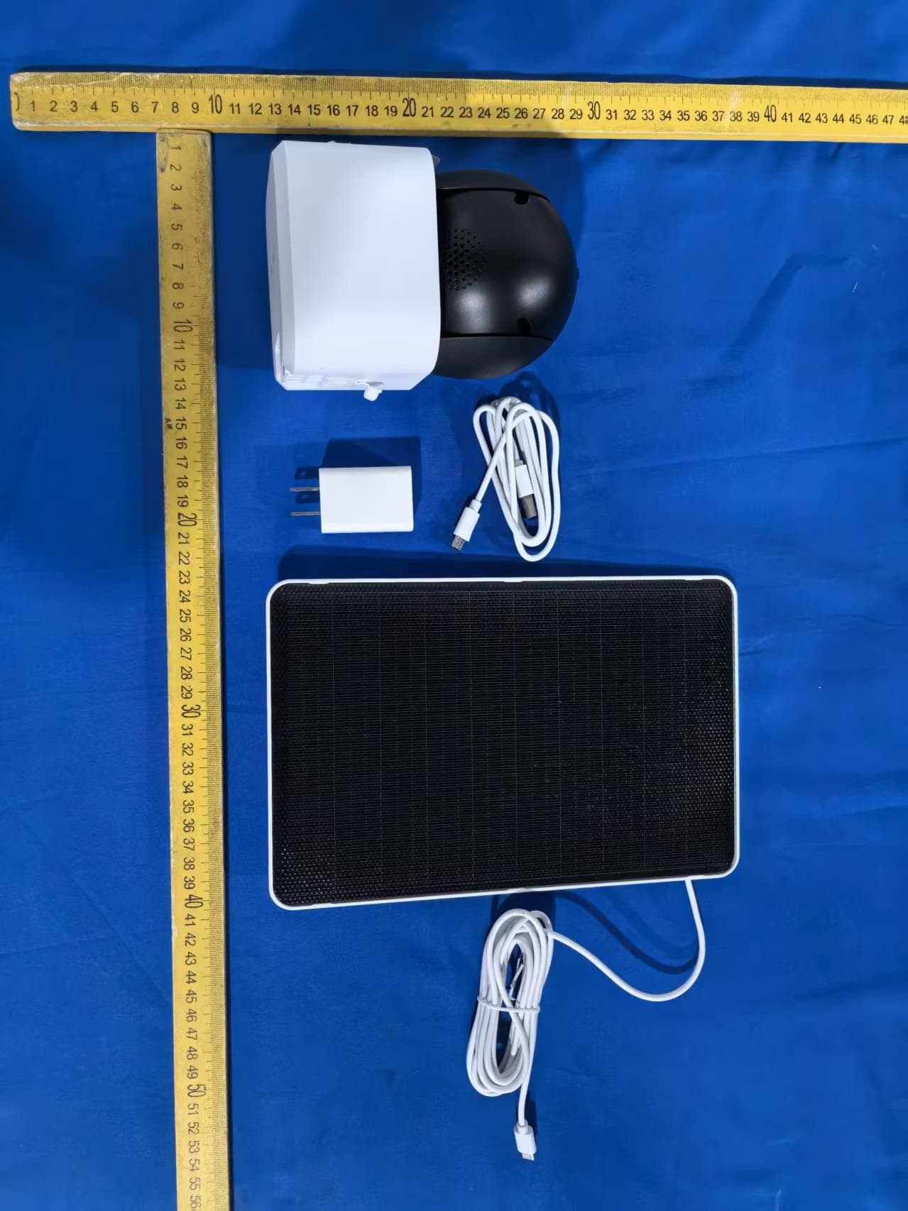
2AG7C-W516T6S3
Aug 12, 2026W7 Zoom
Equipment Class
DTS - Digital Transmission System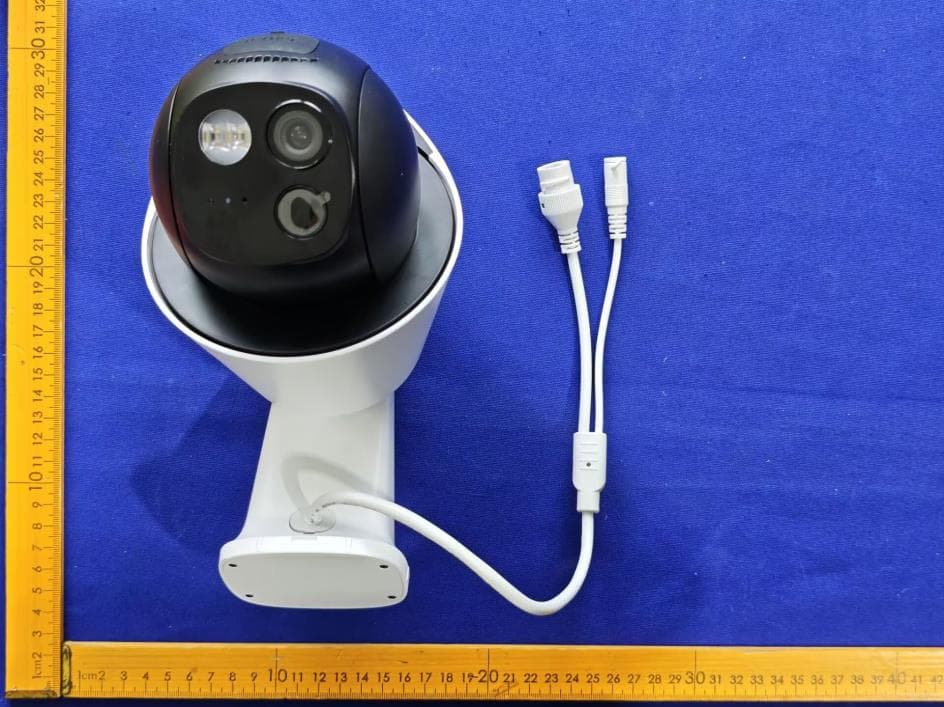
2AG7C-S30T2D1
Aug 05, 2026S7 Dual Plus
Equipment Class
DTS - Digital Transmission System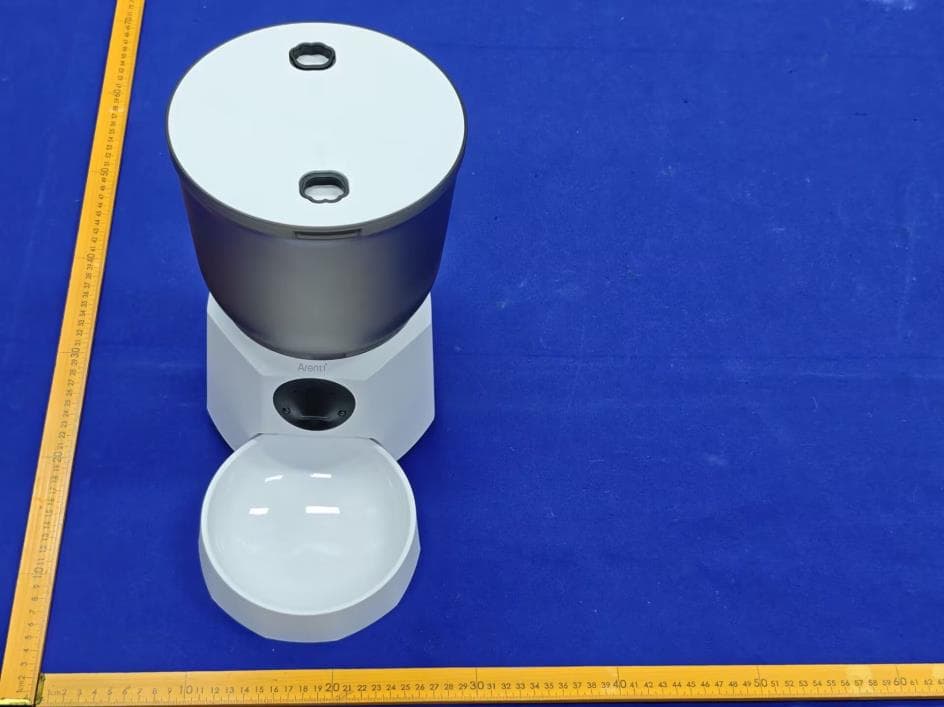
2AG7C-PET11
Jul 26, 2026Pet Feeder Lite
Equipment Class
NII - Unlicensed National Information Infrastructure TX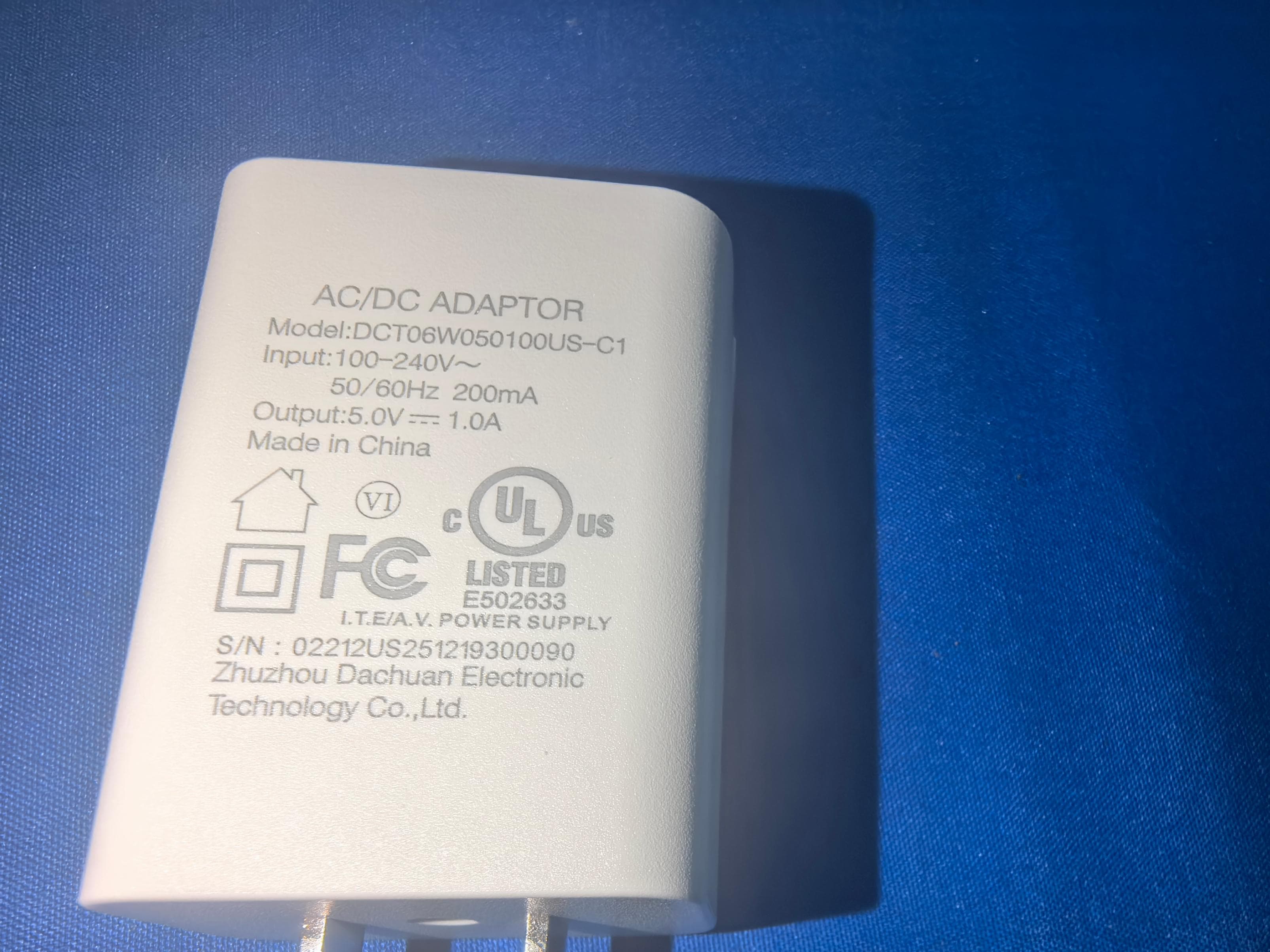
2AG7C-SFW24
Jun 18, 2026Baby Monitor
Equipment Class
NII - Unlicensed National Information Infrastructure TX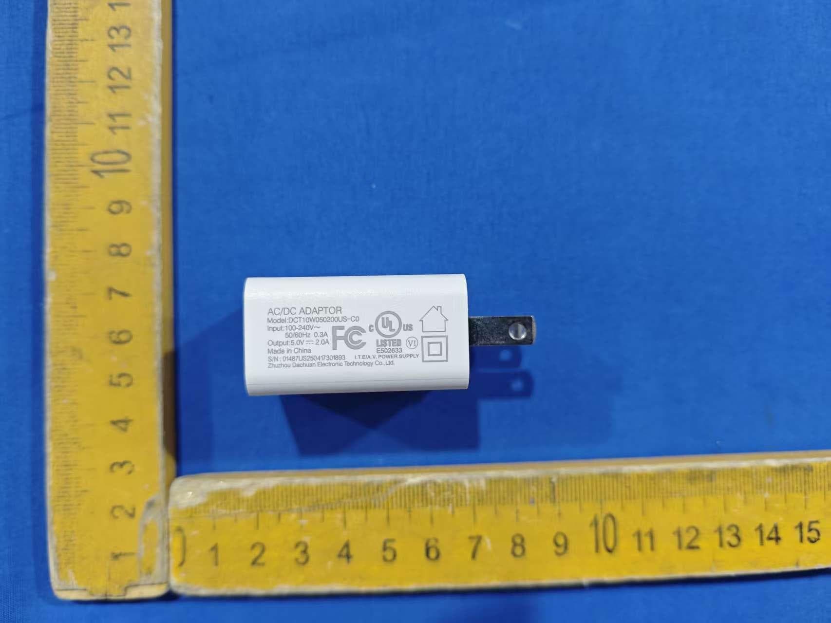
2AG7C-BABY5M
Apr 01, 2026Baby Monitor
Equipment Class
DTS - Digital Transmission System