2AG7CFLIGHT5IP CAMERA
Hangzhou Meari Technology Co., Ltd.
Click to zoom
Application Details
- Equipment Class
- DTS - Digital Transmission System
- Date of Grant
- Mar 17, 2021
- Application Purpose
- Original Equipment
- Date of Application
- Mar 17, 2021
- Equipment Note
- IP CAMERA
- Frequency Range
- 2412.00000000 - 2462.00000000
- Country
- China
Documents & Files
Document Text
Text extracted from the exhibit documents filed with the FCC. Open a document above to read the original.
Users Manual
QUICK GUIDE ORIGINALITY DESIGN SMART AND BEAUTIFUL Flight 5S Consult the checklist below for all components. 1 Bracket screws x2 Flight 5S User manual What's in the box Screws 2 PIR Status light MIC Lens Reset button SD card slot Speaker Description Power Status light AC 100~240V Solid red light on: network is malfunctional Blinking red light: wait for network connection Solid blue light on: camera is working correctly Capture sounds for your video Support local SD Card storage (Max.128GB) Press and hold the 'RESET' for 5 seconds to reset the device (if you have modified settings, they will return to factory defaults) Microphone SD card slot LightTurn the light on/off manually or automatically Reset 3 First turn off the power breaker at your fuse box for your Flight camera. And confirm to power off everything again. OFF ON 1. Loosen the screws of ① and connect the power cable t o the terminal. And then tighten the screws of ①. Make sure t hat one side of white cable ② is inst alled within the bracket, otherwise there will be w ater leakage. 2. Fix the mounting bracket to the wall with bracket screws. WARNING Please confirm that you have turned off your power breaker and then connect terminal with cable. 100~240V AC Step 1 Step 2 Installation 1 2 4 Step 3 Installation Install the camera into the bracket along the direction of the bracket. After the camera is installed in the bracket, fix them with screws. * (Optional) You can adjust the horizontal angle betw een 0 to 120 degress by App. When after installing your flight camera, turn on the power breaker. NOTE: 5 Set up router The router supports the 2.4GHz WiFi (doesn't support the 5GHz), and is connected to the WiFi network.Please set the parameters of the router before connecting the WiFi network, and record the SSID and password of your WiFi. Please keep network available 2.4GHz5GHz Connection Download SmartLife or Tuya Smart is available for both iOS and Android OS. Search the name 'SmartLife','Tuya Smart' in App Store or Google Play, or scan the QR- Code to download the App. ipadAndroidIOS ·Support Download App(IOS&android) 6 Registration process Step 1 Step 2 Input a legal and valid Mobile number or Email address and click "Get Verification Code". Input the verification code to log in. Connection Open the Smart Life App, click "Sign Up", read the "User Agreement Privacy Policy" and click "Agree" . 7 QR Code Configuration Open the Smart Life App, click "My" >> "Home Management" >> "Create a home", and you can customize the home name and related settings . 1 Click "Add Device" or "+", and then select "Security & Sensor" >> "Smart Camera" to add camera. 2 8 QR Code Configuration Power on and reset camera until the status indicator is flashing quickly or a prompt tone is heard, and then click "Next". Then input your WiFi's passwords and click "Next". Click " " to change network. 3 Note: 1) Camera only supports 2.4GHz WiFi network. 2) The number of bits in the ssid and passwords of the router should not exceed 24 digits. 9 QR Code Configuration In this interface, you should scan the QR code in your phone with the camera,when the camera comes out "dong dong dong". And you can complete the configuration about 30s. 4 10 QR Code Configuration When connecting, you should make sure your router,mobile,and camera are as close as possible.When camera added successffully,click " " you could also DIY the camera's name. 5 11 In "Smart Camera" interface,click " ",you can set the camera common functions. Settings Q: Why is it still in the list of devices after reseting? A: The reset device only resets the network configuration of the camera, but cannot change the configuration on the App, remove the camera, and must be deleted by the App. Q: How to cut the camera network to another router? A: First remove and reset the device on the App and then configure the device again by the App. Q: Why doesn't the device identify the SD card? A: It is recommended to plug in SD card after power cut. Confirm whether the SD card is normally available and the format is FAT32. And the TF card can’t be identified when the internet environment is not good. Q: Why I can’t get the notifications with my cell phone App? A: Please confirm that the App has been running on the phone, and the relevant reminder function has been opened;Message notification and authority confirmation in the mobile phone system have been opened. Q: The device cannot be previewed properly? A: Check whether the network is normal, you can place the camera close to the router, and if not, it is recommended to reset the device and add it again. 12 FAQ 13 Record Using SD card or activating the Cloud-Storage Service to keep recording for every moment. Day & Night You can set up a schedule for lighting so that you can get a clear view in the evening. Two-way Audio You can see vistors and hear the isounds by App, which are captured by the camera. PIR When someone passes by, an alarm will be triggered and sent to your App of phone. You can turn on the light alarm on App, so that the light will be on automatically when there is a visitor comes out in the evening. Lighting Control You can turn on or off the light, or adjust the brightness by App. Function FCC Statement: Any Changes or modifications not expressly approved by the party responsible for compliance could void the user’s authority to operate the equipment. This device complies with part 15 of the FCC Rules. Operation is subject to the following two conditions: (1) This device may not cause harmful interference,and (2) this device must accept any interference received, including interference that may cause undesired operation. FCC Radiation Exposure Statement: This equipment complies with FCC radiation exposure limits set forth for an uncontrolled environment .This equipment should be installed and operated with minimum distance 20cm between the radiator and your body. Note: This equipment has been tested and found to comply with the limits for a Cl…
Text truncated - open the document above for the full version.
Cover Letter(s)
Company: Hangzhou Meari Technology Co., Ltd. Add:Room 604-605, Building 1, No.768 Jianghong Road, Changhe street, Binjiang District, Hangzhou, Zhejiang, China Tel: +8615869048127 Fax: +86-571-56565100 E-mail: [email protected] DECLARATION Date: 2021-02-08 FEDERAL COMMUNICATIONS COMMISSION Authorization and Evaluation Division 7435 Oakland Mills Road Columbia, MD 21046 Dear Sir or Madam: We, Hangzhou Meari Technology Co., Ltd., hereby declare that product name: I P CAMERA (model name: Flight 5S, Flight 5T. FCC ID: 2AG7CFLIGHT5). These models are electrically identical with the PCB design, components and electromagnetic compatibility characteristics. And Flight 5S has been tested by BACL. The differences of them are as follows: Model name. Please contact me if there is need for any additional clarification or information. Best Regards, Signature: Typed or Printed Name: Zhiyang Chai Title: Manager
Cover Letter(s)
Company: Hangzhou Meari Technology Co., Ltd. Add:Room 604-605, Building 1, No.768 Jianghong Road, Changhe street, Binjiang District, Hangzhou, Zhejiang, China Tel: +8615869048127 Fax: +86-571-56565100 E-mail: [email protected] FCC Confidential Authorization Date: 2021-02-08 FEDERAL COMMUNICATIONS COMMISSIONS Authorization and Evaluation Division 74 35 Oakland Mills Road Columbia, MD 21046 Subject: Confidentiality Request regarding application for certification of FCC ID: 2AG7CFLIGHT5 To : whom it may concern, In accordance with Sections 0.457 and 0.459 of the Commission’s Rules, Hangzhou Meari Technology Co., Ltd. hereby requests long-term confidential treatment of information accompanying th is application as outlined b elow: Block Diagram Schematics Operation Description The above materials contain proprietary and confidential information not customarily released to the public. The public disclosure of these materials provides unjustified benefits to its competitors in the market. Sincerely Yours, Signature: Typed or Printed Name: Zhiyang Chai Title: Manager
External Photos
EXHIBIT A - EUT EXTERNAL PHOTOGRAPHS
ID Label/Location Info
Input:100-240V~50/60Hz 0.5A Max. S/N:056565099 FCC ID:2AG7CFLIGHT5 Hangzhou Meari Technology Co., Ltd. Room 604-605,Building 1,No.768 Jianghong Road,Changhe street,Binjiang District,Hangzhou,Zhejiang.China
Internal Photos
EXHIBIT B - EUT INTERNAL PHOTOGRAPHS Wi-Fi Antenna
RF Exposure Info
Bay Area Compliance Laboratories Corp. (Kunshan) Report No.: RSHA210208001-00A FCC Part 15.247 Page 13 of 68 FCC §1.1310 & §2.1091 –MAXIMUM PERMISSIBLE EXPOSURE (MPE) Applicable Standard According to subpart §2.1091 and subpart §1.1310, systems operating under the provisions of this section shall be operated in a manner that ensures that the public is not exposed to radio frequency energy level in excess of the Commission’s guidelines. Limits for Maximum Permissible Exposure (MPE) (§1.1310, §2.1091) (B) Limits for General Population/Uncontrolled Exposure Frequency Range (MHz) Electric Field Strength (V/m) Magnetic Field Strength (A/m) Power Density (mW/cm 2 ) Averaging Time (minutes) 0.3-1.34 614 1.63 *(100) 30 1.34-30 824/f 2.19/f *(180/f²) 30 30-300 27.5 0.073 0.2 30 300-1500 / / f/1500 30 1500-100,000 / / 1.0 30 f = frequency in MHz; * = Plane-wave equivalent power density; According to §1.1310 and §2.1091 RF exposure is calculated. Calculated Formulary: Predication of MPE limit at a given distance S = PG/4πR² = power density (in appropriate units, e.g. mW/cm 2 ); P = power input to the antenna (in appropriate units, e.g., mW); G = power gain of the antenna in the direction of interest relative to an isotropic radiator, the power gain factor, is normally numeric gain; R = distance to the center of radiation of the antenna (appropriate units, e.g., cm); Bay Area Compliance Laboratories Corp. (Kunshan) Report No.: RSHA210208001-00A FCC Part 15.247 Page 14 of 68 Calculated Data: Mode Frequency Range (MHz) Antenna Gain Tune-up Output Power Evaluation Distance (cm) Power Density (mW/cm 2 ) MPE Limit (mW/cm 2 ) (dBi) (numeric)(dBm)(mW) 802.11b 2412~2462 4.38 2.74 17.00 50.12 20 0.0273 1.0 802.11g 4.38 2.74 22.50177.83 20 0.0969 1.0 802.11n- HT20 4.38 2.74 22.50177.83 20 0.0969 1.0 802.11n- HT40 2422~2452 4.38 2.74 21.00125.89 20 0.0686 1.0 Note: The Tune-up output power was declared by the Manufacturer. Conclusion: The device meets MPE at distance 20cm.
Test Report
FCC PART 15.247 TEST REPORT For Hangzhou Meari Technology Co., Ltd. Room 604-605,Building 1,No.768 Jianghong Road,Changhe street,Binjiang District,Hangzhou,Zhejiang.China FCC ID: 2AG7CFLIGHT5 Report Type: Original Report Product Type: IP CAMERA Project Engineer: Tyrone Wang Re port Number: RSHA210208001-00A Re port Date: 2021-03-04 Reviewed B y: Oscar Ye EMC Mana ger Prepared By: Bay Area Compliance Laboratories Corp. (Kunshan) No.248 Chenghu Road, Kunshan, Jiangsu province, China Tel: +86-0512-86175000 Fax: +86-0512-88934268 www.baclcorp.com.cn Bay Area Compliance Laboratories Corp. (Kunshan) Report No.: RSHA210208001-00A FCC Part 15.247 Page 2 of 68 TABLE OF CONTENTS GENERAL INFORMATION ....................................................................................................................................... 4 PRODUCT DESCRIPTION FOR EQUIPMENT UNDER TEST (EUT) ..................................................................................... 4 OBJECTIVE ................................................................................................................................................................... 4 RELATED SUBMITTAL(S)/GRANT(S) ............................................................................................................................. 4 TEST METHODOLOGY .................................................................................................................................................. 5 MEASUREMENT UNCERTAINTY .................................................................................................................................... 5 TEST FACILITY ............................................................................................................................................................. 5 SYSTEM TEST CONFIGURATION .......................................................................................................................... 6 DESCRIPTION OF TEST CONFIGURATION ...................................................................................................................... 6 EQUIPMENT MODIFICATIONS ....................................................................................................................................... 6 EUT EXERCISE SOFTWARE .......................................................................................................................................... 6 SUPPORT EQUIPMENT LIST AND DETAILS .................................................................................................................... 9 EXTERNAL I/O CABLE .................................................................................................................................................. 9 BLOCK DIAGRAM OF TEST SETUP ................................................................................................................................ 9 SUMMARY OF TEST RESULTS ............................................................................................................................. 11 TEST EQUIPMENT LIST ......................................................................................................................................... 12 FCC §1.1310 & §2.1091 –MAXIMUM PERMISSIBLE EXPOSURE (MPE) ....................................................... 13 FCC §15.203 - ANTENNA REQUIREMENT ........................................................................................................... 15 APPLICABLE STANDARD ............................................................................................................................................ 15 ANTENNA CONNECTOR CONSTRUCTION .................................................................................................................... 15 FCC §15.207 (a) – AC LINE CONDUCTED EMISSIONS ..................................................................................... 16 APPLICABLE STANDARD ............................................................................................................................................ 16 EUT SETUP ................................................................................................................................................................ 16 EMI TEST RECEIVER SETUP ....................................................................................................................................... 16 TEST PROCEDURE ...................................................................................................................................................... 17 FACTOR & OVER LIMIT CALCULATION ...................................................................................................................... 17 TEST RESULTS SUMMARY .......................................................................................................................................... 17 TEST DATA ................................................................................................................................................................ 17 FCC §15.209, §15.205 & §15.247(d) - SPURIOUS EMISSIONS ............................................................................. 20 APPLICABLE STANDARD ............................................................................................................................................ 20 EUT SETUP ................................................................................................................................................................ 20 EMI TEST RECEIVER SETUP ....................................................................................................................................... 21 TEST PROCEDURE ...................................................................................................................................................... 21 FACTOR & OVER LIMIT CALCULATION .......................................................…
Text truncated - open the document above for the full version.
Test Setup Photos
EXHIBIT C - TEST SETUP PHOTOGRAPHS Conducted Emissions (Front View) Conducted Emissions (Side View) Radiated Emissions (Below 1GHz) Radiated Emissions (Above 1GHz)
Contact Information
Applicant
Zhiyang Chai(Manager)
Test Firm
Bay Area Compliance Laboratories Corp. (Kunshan)Mr. John Chan
[email protected]+86 0512 86175000
Technical Specifications
| # | Rule Parts | Frequency Range | Power Output |
|---|---|---|---|
| 1 | 15C | 2.41 GHz - 2.46 GHz | 161.00 mW |
Other Applications from Hangzhou Meari Technology Co., Ltd.
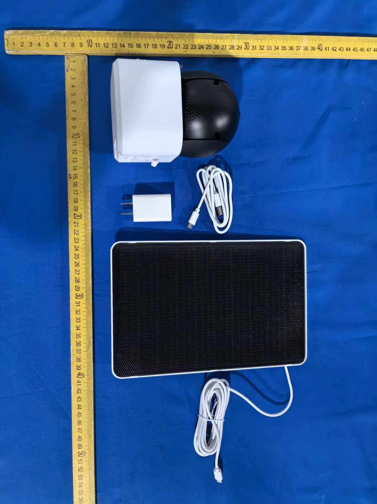
2AG7C-W516T6S3
Aug 12, 2026W7 Zoom
Equipment Class
DTS - Digital Transmission System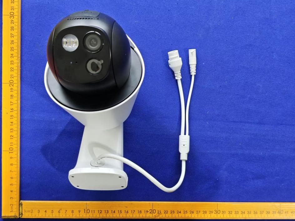
2AG7C-S30T2D1
Aug 05, 2026S7 Dual Plus
Equipment Class
DTS - Digital Transmission System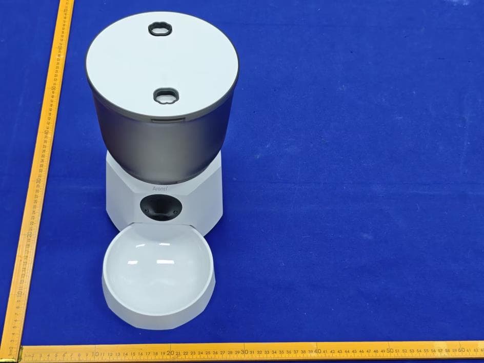
2AG7C-PET11
Jul 26, 2026Pet Feeder Lite
Equipment Class
NII - Unlicensed National Information Infrastructure TX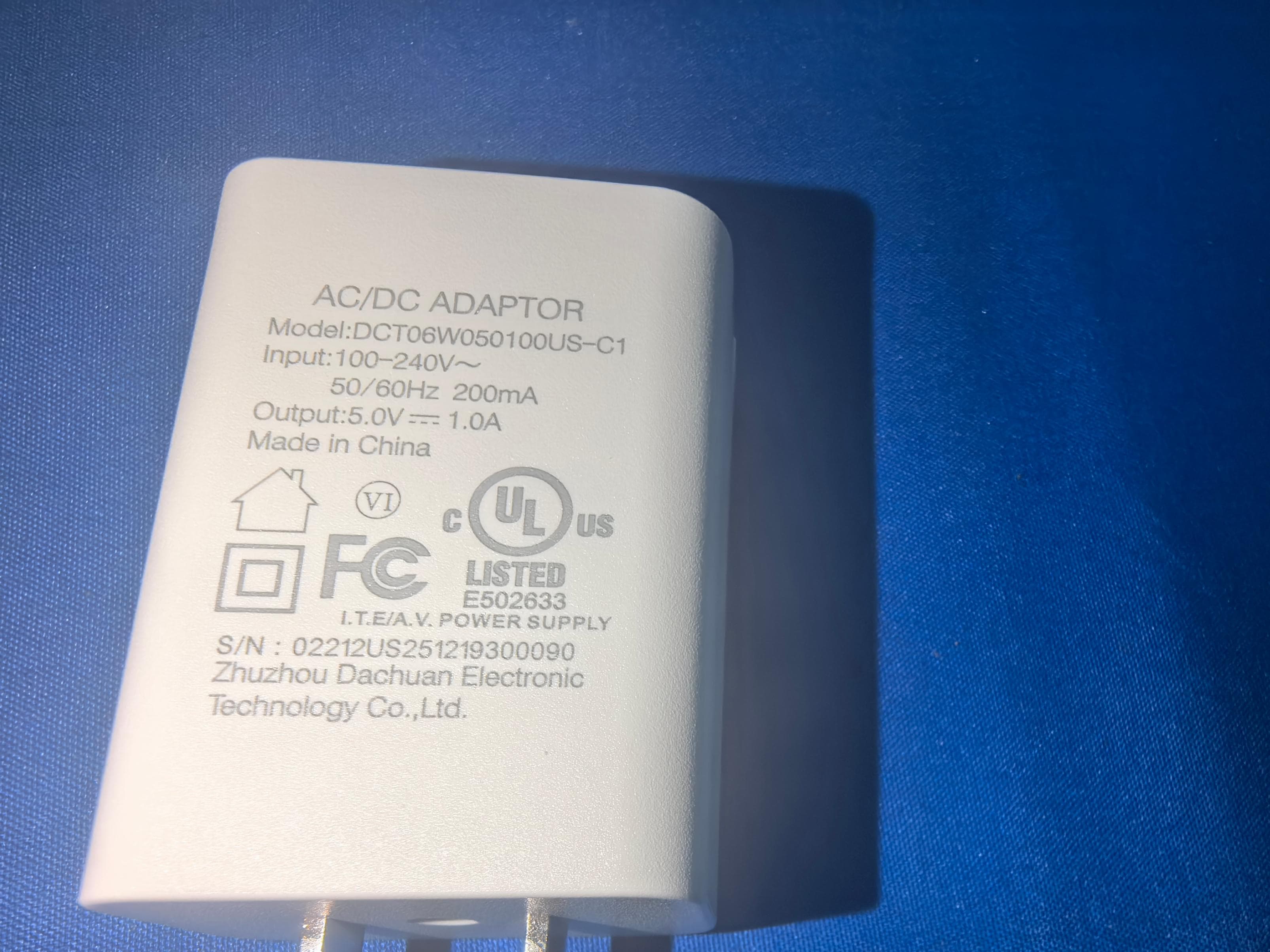
2AG7C-SFW24
Jun 18, 2026Baby Monitor
Equipment Class
NII - Unlicensed National Information Infrastructure TX
2AG7C-BABY5M
Apr 01, 2026Baby Monitor
Equipment Class
DTS - Digital Transmission System