2AGNTMDCMS2458AEVO II Mobile Station
Autel Robotics Co., Ltd.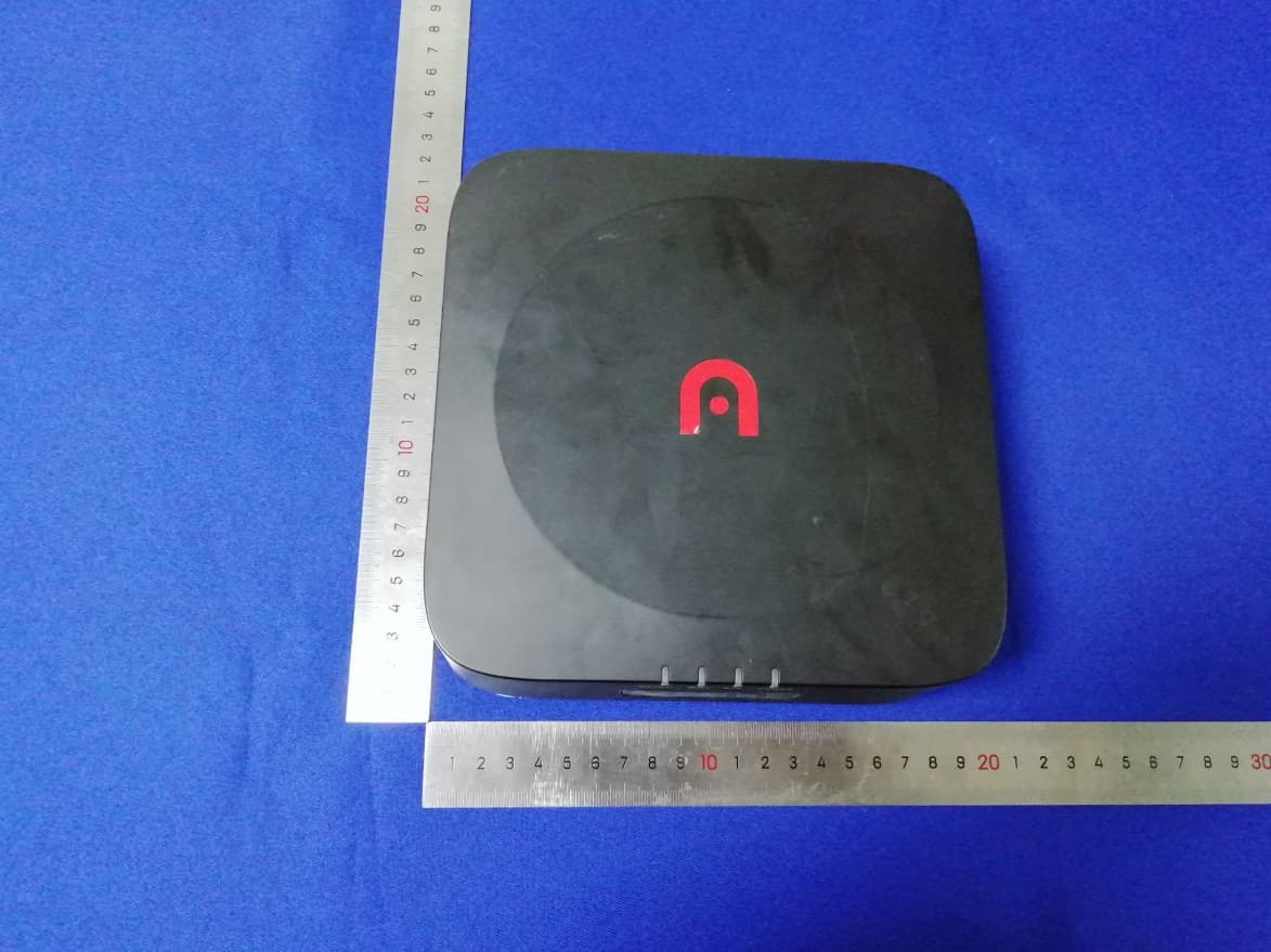
Click to zoom
Application Details
- Equipment Class
- NII - Unlicensed National Information Infrastructure TX
- Date of Grant
- Dec 28, 2020
- Application Purpose
- Original Equipment
- Date of Application
- Dec 28, 2020
- Equipment Note
- EVO II Mobile Station
- Frequency Range
- 5745.00000000 - 5825.00000000
- Company
- Autel Robotics Co., Ltd.
- Country
- China
Documents & Files
Document Text
Text extracted from the exhibit documents filed with the FCC. Open a document above to read the original.
Users Manual
EVO II Mobile Station Quick Guide Disclaimer To ensure safe and successful operation of yourbase station, please strictly follow the operating instructions and steps in this manual. If the user does not abide by the safety operation instructions, DTO Smart will not be responsible for any product damage or loss during use-whether direct or indirect, legal, special, accident or economic loss (including but not limited to loss of profit)- Provide warranty service. Do not use incompatible parts or use any method that does not comply with the official instructions of Autel Smart to modify the product. The safety guidelines in this manual will be updated from time to time. To ensure that you get the latest version, pleasevisit www.auteldrones.com/support/downloads/ battery safety EVO II base preclude the use of lithium polymer batteries. Improper use of lithium polymer batteries can be dangerous. Please ensure that all the following battery usage, charging and storage guidelines are strictly followed. Warning ● Only use the battery and charger provided by DTO Smart. It is prohibited to modify the battery pack and its charger, or use third-party equipment to replace it. ● The electrolyte in the battery is extremely corrosive. If the electrolyte accidentally spills into your eyes or skin, please wash the affected area with clean water immediately and seek medical attention. Precautions 1. According to local radio regulations, use base stations with corresponding frequency bands and comply with local radio laws and regulations. 2. Do not excessively bend and fold the wire during installation. 3. When installing and placing, make sure that the base station is level with the horizontal plane. 4. Use the base station in an open environment free from radio interference. Be sure to turn off other wireless devices in the same frequency band before using it. 5. Please make sure that the antennas of all devices are not blocked during use. 6. Use original accessories or accessories certified by Autel. The use of non-original accessories may cause danger to the safe use of the system. 7. Make sure that no foreign objects (such as water, oil and other liquids, sand, etc.) enter the parts. 8. Do not remove any parts installed at the factory by yourself. 9. When using in rain or snow, please take necessary waterproof measures for the base station. Please use caution in thunder and lightning weather and pay attention to lightning protection. Introduction EVO II GNSS base station (hereinafter referred to as "base station") is a high-precision satellite signal receiver that supports 11-frequencyGPS, Beidou, Galileo and GLONASS navigation systems 1 satellite signal reception of, as well as built-in carefully tuned data transmission The system is convenient for users to use in different application environments. EVO II GNSSbase station asRTKbase station,so that the positioning accuracy EVO II centimeter, but also provides a powerful magnetic immunity, protection and reliable flight operations at ambient power lines, metal construction and other magnetic interference. Item list serial num ber picture name quantity 1 base station (including base station cover) 1 PCS 2 multi-function charger 1 PCS 3 TYPE-C charging cable 1 PCS 4 Document (Quick Guide) 1 component description base station body 2. WiFi indicator 3. RTK indicator 4. Power indicator 5. USB-C charging port 7. Power button 8 Port cover 10. Turntable mounting hole 11. Heat sink tripod 1. Fixing screw 2. Knob 3. Telescopic pole 4. Foot nail ready for charging Short press (<1 second) the power button once to check the battery level. Description of power indicator Green: Electricity>60% Yellow: Electricity>30% Red: Electricity>10% Red flashing slowly: Electricity <10% charging methodcharge When using thefor the first time, be sure to fullythe battery. Please use a dedicated charger to charge the base station. 1、 Plug the Type-C power cord into the Type-C port of the base station, and the base station will automatically enter the charging mode (either when it is turned on or off). 2、 When charging, the base station power indicator light flashes, and the battery power is indicated by different colors. When connected to a charging power source, the base station power indicator light is steady green to indicate that it is fully charged. Turn on/off the base station Turn on The base station has 2 working modes, namely normal mode and disabled RTK mode, which can be used in different operating scenarios. Follow the instructions below to turn on the base station and enter different working modes. 1. When the base station is off, press and hold the power button for 1 second to enter the normal mode. 2. When the base station is off, press and hold the power button for 3 seconds to enter the disabled RTK mode. When entering, the buzzer will beep 3 times and the RTK indicator will be steady red. Turn off Long press the power button for 1 second to turn off the RTK indicator light Description Green: Number of satellites>16, good signal (normal flight) Yellow: Number of satellites 6-15, poor signal (it is recommended to adjust the base station to an open area) Red Slow flashing: number of satellites <6, poor signal (recommend the base station to be placed in an open area) Light off: no RTK signal (indoors or abnormal base station RTK) use to connect to a ground station or aircraft connection method Take the normal mode as an example, the specific operation is as follows. Connect the ground station to the base station 1、 turn on the power of thestation; 2、 turn on the remote control and run the Autel Voyager App, select "Settings -> Base Station", you can see the base station wifi hotspot after entering, enter the password: 12345678, wait a few seconds until the remote control is successfully connected to the base station;; 3、 exitSetting interface, enter the mission flight interface, click the gear icon in the upper right corner, enter the settings menu, click "remote cont…
Text truncated - open the document above for the full version.
Cover Letter(s)
Autel Robotics Co., Ltd. Agent Authorization Company: Autel Robotics Co., Ltd. Address: 9th Floor, Bldg.B1, Zhiyuan, 1001 Xueyuan Rd. Xili, Nanshan, Shenzhen, China Product Type: EVO II Mobile Station Model Number(s): MDCMS-1 Product Description: EVO II Mobile Station We authorize MiCOM Labs Inc., 575 Boulder Court, Pleasanton, California 94566, USA, to act on our behalf on all matters concerning the certification of above named equipment. We declare that MiCOM Labs Inc. is allowed to forward all information related to the approval and certification of equipment to the regulatory agencies as required and to discuss any issues concerning the approval application. Any and all acts carried out by MiCOM Labs on our behalf shall have the same effect as acts of our own. Signature: Date: 2020-12-22 Name: Xiangxi Pan Title: President Company: Autel Robotics Co., Ltd.
Cover Letter(s)
Autel Robotics Co., Ltd. Office of Engineering Technology Federal Communications Commission 7435 Oakland Mills Road Columbia, MD 21046 USA Date: 2020-12-22 Subject; Request for Confidentiality FCC ID: 2AGNTMDCMS2458A To Whom It May Concern, Pursuant to the provisions of the Commission’s rules Title 47 Sections §0.457 and §0.459, we are requesting the Commission to withhold the following attachment(s) as confidential documents from public disclosure indefinitely. These documents contain detailed system and equipment descriptions and are considered as proprietary information in operation of the equipment. The public disclosure of these documents might be harmful to our company and would give competitors an unfair advantage in the market. Schematic Diagram Block Diagram Parts List Operational Description Tune-up Procedure FCC Software Security Requirements for UNII devices In additional to above mentioned documents, in order to comply with the marketing regulations in Title 47 CFR §2.803 and the importation rules in Title 47 CFR §2.1204, while ensuring that business sensitive information remains confidential until the actual marketing of newly authorized devices, we request Short Term Confidentiality of the following attachment(s); External Photos Test Setup Photos Internal Photos User Manual For 45 days, pursuant to Public Notice DA 04-1705. OR For 180 days pursuantto KDB 726920 D01. It is our understanding that all measurement test reports, FCC ID label format and correspondence during the certification review process cannot be granted as confidential documents and this information will be available for public review once the grant of equipment authorization is issued. Sincerely, Signature: Name: Xiangxi Pan Title: President
Cover Letter(s)
FCC Software Configuration Control Declaration Autel Robotics Co., Ltd. FCC Software Configuration Control Declaration Date: December 22, 2020 Federal Communications Commission Authorization and Evaluation Division 7435 Oakland Mills Road Columbia, MD 21046 Attn: OET Dept. Product/ Model Number: EVO II Mobile Station/ MDCMS-1 Regarding FCC Country Code Selection guidelines identified in KDB 594280 D01 V02r01. “All applications for equipment authorization for transmitters that can have radio parameters, or other technical parameters, reported to the Commission set by software must have an attestation indicating that no third party will have software, or configuration control, to program the device out of compliance of the technical rules under which it has been certified.” We declare that no third party will have software, or configuration control, to program the device out of compliance of the technical rules under which it has been certified. Name: Xiangxi Pan Date: 2020/12/22 Title: President Signature of applicant
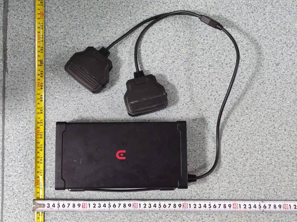
External Photos
Test Model No.: MDCMS‐1
ID Label/Location Info
Label &Label location Size:61.6mm x 139.56mm
Internal Photos
Test Model No.: MDCMS‐1 GPS antenna close‐up of the 5.1G&5.8G WiFi antenna photo 5.1G&5.8G WiFi antenna
RF Exposure Info
FCC ID: 2AGNTMDCMS2458A RF Exposure Evaluation Limits The criteria listed in the following table shall be used to evaluate the environment impact of human exposure to radio frequency (RF) radiation as specified in 1.1307(b) Limits for Maximum Permissible Exposure (MPE) Frequency range (MHz) Electric field strength (V/m) Magnetic field strength (A/m) Power density (mW/cm 2 ) Averaging time (minutes) (A) Limits for Occupational/Controlled Exposures 0.3–3.0 614 1.63 *(100) 6 3.0–30 1842/f 4.89/f *(900/f 2 ) 6 30–300 61.4 0.163 1.0 6 300–1500 f/300 6 1500–100,000 5 6 (B) Limits for General Population/Uncontrolled Exposure 0.3–1.34 614 1.63 *(100) 30 1.34–30 824/f 2.19/f *(180/f 2 ) 30 30–300 27.5 0.073 0.2 30 300–1500 f/1500 30 1500–100,000 1.0 30 f = frequency in MHz Friis transmission formula: Pd = (Pout*G)/(4*pi*r 2 ) Where Pd = power density in mW/cm 2 , Pout = output power to antenna in mW; G = gain of antenna in linear scale, Pi = 3.1416; R = distance between observation point and center of the radiator in cm Pd id the limit of MPE, 1 mW/cm 2 . If we know the maximum gain of the antenna and the total power input to the antenna, through the calculation, we will know the distance r where the MPE limit is reached. Test Procedure Software provided by client enabled the EUT to transmit and receive data at lowest, middle and highest channel individually. Test Result of RF Exposure Evaluation Wireless function Output power to antenna (dBm) Antenna Gain(dBi) Output power to antenna (mW) Power Density at R=20cm (mW/cm 2 ) Limit (mW/cm 2 ) Result 5.1G 17.11 4.20 51.404 0.02690 1.000 PASS 5.8G 19.19 3.40 82.985 0.03612 1.000 PASS
Test Report
Global United Technology Services Co., Ltd. Report No.: GTSL202012000158F01 Authorized Signature: Robinson Luo Laboratory Manager This results shown in this test report refer only to the sample(s) tested, this test report cannot be reproduced, except in full, without prior written permission of the company. The report would be invalid without specific stamp of test institute and the signatures of compiler and approver. Page 1 of 34 TEST REPORT Applicant: Autel Robotics Co., Ltd. Address of Applicant: 9th Floor, Bldg.B1, Zhiyuan, 1001 Xueyuan Rd. Xili, Nanshan, Shenzhen, China Manufacturer/Factory: Autel Robotics Co., Ltd. Address of Manufacturer/Factory: 9th Floor, Bldg.B1, Zhiyuan, 1001 Xueyuan Rd. Xili, Nanshan, Shenzhen, China Equipment Under Test (EUT) Product Name: EVO II Mobile Station Model No.: MDCMS-1 Trade Mark: AUTEL FCC ID: 2AGNTMDCMS2458A Applicable standards: FCC CFR Title 47 Part 15 Subpart E Section 15.407 Date of sample receipt: Dec. 09, 2020 Date of Test: Dec. 09 – Dec. 15, 2020 Date of report issue: Dec. 15, 2020 Test Result : PASS * * In the configuration tested, the EUT complied with the standards specified above. Report No.: GTSL202012000158F01 Global United Technology Services Co., Ltd. No. 123-128, Tower A, Jinyuan Business Building, No.2, Laodong Industrial Zone, Xixiang Road, Baoan District, Shenzhen, Guangdong, China 518102 Telephone: +86 (0) 755 2779 8480 Fax: +86 (0) 755 2779 8960 Page 2 of 34 2 Version Version No. Date Description 00 Dec. 15, 2020 Original Prepared By: Date: Dec. 15, 2020 Project Engineer Check By: Date: Dec. 15, 2020 Reviewer Report No.: GTSL202012000158F01 Global United Technology Services Co., Ltd. No. 123-128, Tower A, Jinyuan Business Building, No.2, Laodong Industrial Zone, Xixiang Road, Baoan District, Shenzhen, Guangdong, China 518102 Telephone: +86 (0) 755 2779 8480 Fax: +86 (0) 755 2779 8960 Page 3 of 34 3 Contents Page 1 COVER PAGE ........................................................................................................................................... 1 2 VERSION .................................................................................................................................................. 2 3 CONTENTS .............................................................................................................................................. 3 4 TEST SUMMARY ..................................................................................................................................... 4 4.1 MEASUREMENT UNCERTAINTY ............................................................................................................. 4 5 GENERAL INFORMATION ...................................................................................................................... 5 5.1 GENERAL DESCRIPTION OF EUT ......................................................................................................... 5 5.2 TEST MODE ........................................................................................................................................ 6 5.3 TEST FACILITY .................................................................................................................................... 6 5.4 TEST LOCATION .................................................................................................................................. 6 5.5 DESCRIPTION OF SUPPORT UNITS ....................................................................................................... 6 5.6 DEVIATION FROM STANDARDS ............................................................................................................. 6 5.7 ABNORMALITIES FROM STANDARD CONDITIONS .................................................................................... 6 6 TEST INSTRUMENTS LIST ..................................................................................................................... 7 7 TEST RESULTS AND MEASUREMENT DATA ...................................................................................... 9 7.1 ANTENNA REQUIREMENT: .................................................................................................................... 9 7.2 CONDUCTED EMISSIONS ................................................................................................................... 10 7.3 EMISSION BANDWIDTH AND 99% OCCUPIED BANDWIDTH .................................................................... 13 7.4 PEAK TRANSMIT POWER ................................................................................................................... 15 7.5 POWER SPECTRAL DENSITY .............................................................................................................. 17 7.6 BAND EDGE ...................................................................................................................................... 20 7.7 RADIATED EMISSION ......................................................................................................................... 24 7.8 FREQUENCY STABILITY ...................................................................................................................... 32 8 TEST SETUP PHOTO ............................................................................................................................ 34 9 EUT CONSTRUCTIONAL DETAILS ..................................................................................................... 34 Report No.: GTSL202012000158F01 Global United Technology Services Co., Ltd. No. 123-128, Tower A, Jinyuan Business Building, No.2, Laodong Industrial Zone, Xixiang Road, Baoan District, Shenzhen, Guangdong, China 518102 Telephone: +86 (0) 755 2779 8480 Fax: +86 (0) 755 2779 8960 Page 4 of 34 4 Test Summary Test Item Section in CFR 47 Result Antenna requirement 15.203 PASS AC Power Line Conducted Emission 15.207 PASS Peak Transmit Power 15.407(a)(1) PASS Power Spectral Density 15.407(a)(1)…
Text truncated - open the document above for the full version.
Test Report
Global United Technology Services Co., Ltd. Report No.: GTSL202012000158F02 Authorized Signature: Robinson Luo Laboratory Manager This results shown in this test report refer only to the sample(s) tested, this test report cannot be reproduced, except in full, without prior written permission of the company. The report would be invalid without specific stamp of test institute and the signatures of compiler and approver. Page 1 of 34 TEST REPORT Applicant: Autel Robotics Co., Ltd. Address of Applicant: 9th Floor, Bldg.B1, Zhiyuan, 1001 Xueyuan Rd. Xili, Nanshan, Shenzhen, China Manufacturer/Factory: Autel Robotics Co., Ltd. Address of Manufacturer/Factory: 9th Floor, Bldg.B1, Zhiyuan, 1001 Xueyuan Rd. Xili, Nanshan, Shenzhen, China Equipment Under Test (EUT) Product Name: EVO II Mobile Station Model No.: MDCMS-1 Trade Mark: AUTEL FCC ID: 2AGNTMDCMS2458A Applicable standards: FCC CFR Title 47 Part 15 Subpart E Section 15.407 Date of sample receipt: Dec. 09, 2020 Date of Test: Dec. 09 – Dec. 15, 2020 Date of report issued: Dec. 15, 2020 Test Result : PASS * * In the configuration tested, the EUT complied with the standards specified above. Report No.: GTSL202012000158F02 Global United Technology Services Co., Ltd. No. 123-128, Tower A, Jinyuan Business Building, No.2, Laodong Industrial Zone, Xixiang Road, Baoan District, Shenzhen, Guangdong, China 518102 Telephone: +86 (0) 755 2779 8480 Fax: +86 (0) 755 2779 8960 Page 2 of 34 2 Version Version No. Date Description 00 Dec. 15, 2020 Original Prepared By: Date: Dec. 15, 2020 Project Engineer Check By: Date: Dec. 15, 2020 Reviewer Report No.: GTSL202012000158F02 Global United Technology Services Co., Ltd. No. 123-128, Tower A, Jinyuan Business Building, No.2, Laodong Industrial Zone, Xixiang Road, Baoan District, Shenzhen, Guangdong, China 518102 Telephone: +86 (0) 755 2779 8480 Fax: +86 (0) 755 2779 8960 Page 3 of 34 3 Contents Page 1 COVER PAGE ........................................................................................................................................... 1 2 VERSION .................................................................................................................................................. 2 3 CONTENTS .............................................................................................................................................. 3 4 TEST SUMMARY ..................................................................................................................................... 4 4.1 MEASUREMENT UNCERTAINTY ............................................................................................................ 4 5 GENERAL INFORMATION ...................................................................................................................... 5 5.1 GENERAL DESCRIPTION OF EUT ......................................................................................................... 5 5.2 TEST MODE ........................................................................................................................................ 7 5.3 DESCRIPTION OF SUPPORT UNITS ....................................................................................................... 7 5.4 DEVIATION FROM STANDARDS ............................................................................................................. 7 5.5 ABNORMALITIES FROM STANDARD CONDITIONS ................................................................................... 7 5.6 TEST FACILITY .................................................................................................................................... 8 5.7 TEST LOCATION ................................................................................................................................. 8 6 TEST INSTRUMENTS LIST ..................................................................................................................... 9 7 TEST RESULTS AND MEASUREMENT DATA .................................................................................... 11 7.1 ANTENNA REQUIREMENT ................................................................................................................... 11 7.2 CONDUCTED EMISSIONS ................................................................................................................... 12 7.3 CONDUCTED PEAK OUTPUT POWER .................................................................................................. 15 7.4 CHANNEL BANDWIDTH ...................................................................................................................... 16 7.5 POWER SPECTRAL DENSITY ............................................................................................................. 19 7.6 BAND EDGE ...................................................................................................................................... 22 7.6.1 Radiated Emission Method ........................................................................................................ 22 7.7 SPURIOUS EMISSION ......................................................................................................................... 26 7.7.1 Radiated Emission Method ........................................................................................................ 26 7.8 FREQUENCY STABILITY ..................................................................................................................... 32 8 TEST SETUP PHOTO ............................................................................................................................ 34 9 EUT CONSTRUCTIONAL DETAILS ..................................................................................................... 34 Report No.: GTSL202012000158F02 Global United Technology Services Co., Ltd. No. 123-128, Tower A, Jinyuan Business Building, No.2, Laodong Industrial Zone, Xixiang Road, Baoan District, Shenzhen, Guangdong, C…
Text truncated - open the document above for the full version.
Test Setup Photos
Test Model No.: MDCMS-1 Radiated Emission Conducted Emission
Contact Information
Applicant
Xiangxi Pan
Technical Contact
Test Firm
Global United Technology Services Co. Ltd.Robinson Lo
Technical Specifications
| # | Rule Parts | Frequency Range | Power Output |
|---|---|---|---|
| 2 | 15E | 5.75 GHz - 5.83 GHz | 82.98 mW |
Other Applications from Autel Robotics Co., Ltd.
2AGNTMDM240958A
Feb 16, 2024Autel Titan
Equipment Class
NII - Unlicensed National Information Infrastructure TX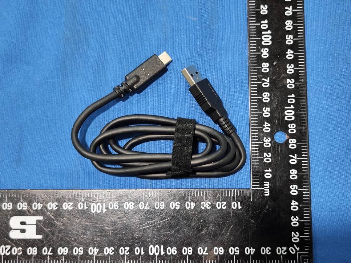
2AGNTMDX600958A
Jan 16, 2024EVO Max
Equipment Class
FDS - Part 15 Field Disturbance Sensor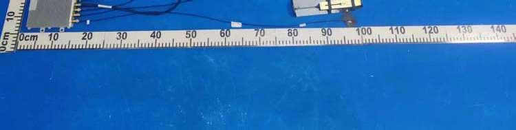
2AGNTNEST
Sep 13, 2023Nest
Equipment Class
JAD - Part 15 Class A Digital Device
2AGNTL35T
Aug 18, 2023DG-L35T
Equipment Class
NII - Unlicensed National Information Infrastructure TX2AGNTMDC240958A
Jul 31, 2022EVO II V3
Equipment Class
NII - Unlicensed National Information Infrastructure TX