2AHNM-SMRZB143Smart Cable
Develco Products
Click to zoom
Application Details
- Equipment Class
- DTS - Digital Transmission System
- Date of Grant
- May 13, 2020
- Application Purpose
- Original Equipment
- Date of Application
- May 13, 2020
- Equipment Note
- Smart Cable
- Frequency Range
- 2405.00000000 - 2480.00000000
- Company
- Develco Products
- Country
- Denmark
Documents & Files
Document Text
Text extracted from the exhibit documents filed with the FCC. Open a document above to read the original.
Users Manual
eng Other information • The Smart Cable will automatically switch off if the load exceeds 16 A or the internal temperature gets too high. • In case of power failure, the device will restore itself to the on/off status it had before the power failure. Disposal Dispose the product properly at the end of life. This is electronic waste which should be recycled. • In case of a bad or weak signal, change the location of the Smart Cable or your gateway. • If the search for a gateway has timed out, a short press on the LED button will restart it.. 4. After releasing the button, the red LED will stay on for 2-5 seconds. During that time, the device must not be switched off or unplugged. Resetting Placement • Place the smart cable indoors at a temperature between 0-50°C. • If the device is used as signal amplifier, please position the device in between the gateway and other connected devices. 1. Unscrew the inner four screws on the back of the device. 2. Open the casing by pushing the fastening on both sides with a flathead screwdriver. Getting started Precautions • Be careful that no liquid gets into the smart cable since it may damage the equipment. • Do not remove the product label as it contains important information. • Avoid switching maximum loads frequently on or off, in order to sustain a long life for the smart cable . Adjusting the cable fitting for different size cables is quick and easy. If the opening is not big enough for your cable, simply grab and remove the slide to allow for a larger cable. Different Cable Sizes Product description The Smart Cable converts power cables to remotely controlled units that also monitor the power consumption. The Smart Cable can be used, where there is no space for a smart plug or where a higher load (up to 16 Amp) is required. The Smart Cable has a flexible cable connection and is not dependent on the plug type. Version 2.1 INSTALLATION MANUAL Smart Cable 3. Cut your cord in half with wire strippers, remove about 25 mm of the insulation from both ends of the cable freeing the three wires. Remove about 5 mm of the insulation from these three wires on both ends of the cable. 4. Run the exposed cable underneath the clamps and insert the correct wires into the correct ports (Live to Live, Ground to Ground, Neutral to Neutral). Secure the wires by tightening the screws. 5. Attach the cable running to the appliance to the ”LOAD” ports and the end which runs to the outlet into the ”IN” ports) SCHRACK Modes Fault finding 6. With the wires secured, tighten the screws of the cable clamps to secure the cable. 13. The Smart Cable’s output is active when the green LED is on. 7. Replace the top of the device and tighten in the four inner screws to close the casing. 8. Ensure that the cables are securely fastened. 9. Connect the Smart Cable to the power outlet. 10. The Smart Cable will start searching (up to 15 minutes) for a Zigbee network to join. 11. Make sure that the Zigbee network is open for joining devices and will accept the Smart Cable. 12. While searching for a network, the red LED is flashing every second. SEARCHING GATEWAY MODE The red LED is flashing every second ON MODE Green LED means that the smart cable output is active (relay is on). The relay can be switched on and off by pushing the button. OFF MODE When there is no light in the LED, the Smart Cable output is inactive. Resetting is needed if you want to connect your Smart Cable to another gateway, if you need to perform a factory reset to remove abnormal behaviour, or if you need to reset accumulative registers and logs. STEPS FOR RESETTING 1. Connect the Smart Cable to the power outlet. 2. Press and hold down the button on the device. 3. Hold the button down until the red LED flashes continuously, then release the button. a. b. c. d. e. f. h. i. g. CE certification The CE mark affixed to this product confirms its compliance with the European Directives which apply to the product and, in particular, its compliance with the harmonized standards and specifications. IN ACCORDANCE WITH THE DIRECTIVES • Radio Equipment Directive (RED) 2014/53/EU • RoHS Directive 2015/863/EU amending 2011/65/EU Develco Products assumes no responsibility for any errors, which may appear in this manual. Furthermore, Develco Products reserves the right to alter the hardware, software, and/ or specifications detailed herein at any time without notice, and Develco Products does not make any commitment to update the information contained herein. All the trademarks listed herein are owned by their respective owners. All rights reserved. Other certifications • Zigbee Home Automation 1.2 certified Distributed by Develco Products A/S Tangen 6 8200 Aarhus N Denmark www.develcoproducts.com FCC statement Changes or modifications to the equipment not expressly approved by the party responsible for compliance could void the user’s authority to operate the equipment. NOTE: This equipment has been tested and found to comply with the limits for a Class B digital device, pursuant to Part 15 of the FCC Rules. These limits are designed to provide reasonable protection against harmful interference in a residential installation. This equipment generates, uses and can radiate radio frequency energy and, if not installed and used in accordance with the instructions, may cause harmful interference to radio communications. However, there is no guarantee that interference will not occur in a particular installation. If this equipment does cause harmful interference to radio or television reception, which can be determined by turning the equipment off and on, the user is encouraged to try to correct the interference by one or more of the following measures: • Reorient or relocate the receiving antenna. • Increase the separation between the equipment and receiver. • Connect the equipment into an outlet on a circuit different from that to which the receiver is connected. • Consult the dealer or an experienced radio/TV technician for help. This dev…
Text truncated - open the document above for the full version.
External Photos
SGS-CSTC Standards Technical Services Co., Ltd. Shenzhen Branch Page: 1 of 4 External Photos for SZEM2003002033CR FCC ID: 2AHNM-SMRZB143 SGS-CSTC Standards Technical Services Co., Ltd. Shenzhen Branch Page: 2 of 4 1 EUT Constructional Details SGS-CSTC Standards Technical Services Co., Ltd. Shenzhen Branch Page: 3 of 4 SGS-CSTC Standards Technical Services Co., Ltd. Shenzhen Branch Page: 4 of 4
ID Label/Location Info
Size: 26*71mm
Internal Photos
SGS-CSTC Standards Technical Services Co., Ltd. Shenzhen Branch Page: 1 of 3 Internal Photos for SZEM2003002033CR FCC ID: 2AHNM-SMRZB143 SGS-CSTC Standards Technical Services Co., Ltd. Shenzhen Branch Page: 2 of 3 1 EUT Constructional Details SGS-CSTC Standards Technical Services Co., Ltd. Shenzhen Branch Page: 3 of 3
RF Exposure Info
SGS-CSTC Standards Technical Services Co., Ltd. Shenzhen Branch Report No.: SZEM200300203302 Page: 1 of 7 Keny Xu EMC Laboratory Manager 1 Cover page RF Exposure Evaluation Report Application No.: SZEM2003002033CR Applicant: Develco Products Address of Applicant: Olof Palmes Alle 40, Aarhus N, 8240, Denmark Manufacturer: Develco Products A/S Address of Manufacturer: Tangen 6, 8200 Aarhus N, Denmark Factory: GPV Address of Factory: 834 Moo 4, Bangpoo Industrial Estate Soi 11, 12 Sukhumvit Road Praksa Muang Samutprakar 10280 Thailand Equipment Under Test (EUT): EUT Name: Smart Cable Model No.: SMRZB-143 Trade Mark: Develco Products FCC ID: 2AHNM-SMRZB143 Standards: 47 CFR Part 1.1307 47 CFR Part 1.1310 47 CFR Part 2.1093 KDB447498D01 General RF Exposure Guidance v06 Date of Receipt: 2020-03-31 Date of Test: 2020-04-06 to 2020-04-25 Date of Issue: 2020-04-27 Test Result : PASS* * In the configuration tested, the EUT complied with the standards specified above. SGS-CSTC Standards Technical Services Co., Ltd. Shenzhen Branch Report No.: SZEM200300203302 Page: 2 of 7 2 Version Revision Record Version Chapter Date Modifier Remark 01 2020-04-27 Original Authorized for issue by: Bill Chen /Project Engineer Eric Fu /Reviewer SGS-CSTC Standards Technical Services Co., Ltd. Shenzhen Branch Report No.: SZEM200300203302 Page: 3 of 7 3 Contents Page 1 COVER PAGE .............................................................................................................................................. 1 2 VERSION ...................................................................................................................................................... 2 3 CONTENTS .................................................................................................................................................. 3 4 GENERAL INFORMATION .......................................................................................................................... 4 4.1 GENERAL DESCRIPTION OF EUT ................................................................................................................. 4 4.2 TEST LOCATION .......................................................................................................................................... 5 4.3 TEST FACILITY ............................................................................................................................................ 5 4.4 DEVIATION FROM STANDARDS ..................................................................................................................... 5 4.5 ABNORMALITIES FROM STANDARD CONDITIONS ............................................................................................ 5 4.6 OTHER INFORMATION REQUESTED BY THE CUSTOMER ................................................................................. 5 5 RF EXPOSURE EVALUATION .................................................................................................................... 6 5.1 RF EXPOSURE COMPLIANCE REQUIREMENT ................................................................................................ 6 5.1.1 Limits ................................................................................................................................................ 6 5.1.2 Test Procedure ................................................................................................................................ 6 5.1.3 EUT RF Exposure Evaluation .......................................................................................................... 7 SGS-CSTC Standards Technical Services Co., Ltd. Shenzhen Branch Report No.: SZEM200300203302 Page: 4 of 7 4 General Information 4.1 General Description of EUT Power Supply: AC 110V/60Hz, 16A MAX Operation Frequency: 2405MHz to 2480MHz Modulation Type: O-QPSK Number of Channels: 16 Channel Spacing: 5MHz Antenna Gain: 2dBi Antenna Type: PCB SGS-CSTC Standards Technical Services Co., Ltd. Shenzhen Branch Report No.: SZEM200300203302 Page: 5 of 7 4.2 Test Location All tests were performed at: SGS-CSTC Standards Technical Services Co., Ltd. Shenzhen Branch No. 1 Workshop, M-10, Middle section, Science & Technology Park, Shenzhen, Guangdong, China 518057 Telephone: +86 (0) 755 2601 2053 Fax: +86 (0) 755 2671 0594 No tests were sub-contracted. 4.3 Test Facility The test facility is recognized, certified, or accredited by the following organizations: • A2LA (Certificate No. 3816.01) SGS-CSTC Standards Technical Services Co., Ltd., Shenzhen EMC Laboratory is accredited by the American Association for Laboratory Accreditation(A2LA). Certificate No. 3816.01. • VCCI The 3m Fully-anechoic chamber for above 1GHz, 10m Semi-anechoic chamber for below 1GHz, Shielded Room for Mains Port Conducted Interference Measurement and Telecommunication Port Conducted Interference Measurement of SGS-CSTC Standards Technical Services Co., Ltd. have been registered in accordance with the Regulations for Voluntary Control Measures with Registration No.: G-20026, R-14188, C-12383 and T-11153 respectively. • FCC –Designation Number: CN1178 SGS-CSTC Standards Technical Services Co., Ltd., Shenzhen EMC Laboratory has been recognized as an accredited testing laboratory. Designation Number: CN1178. Test Firm Registration Number: 406779. • Innovation, Science and Economic Development Canada SGS-CSTC Standards Technical Services Co., Ltd., Shenzhen EMC Laboratory has been recognized by ISED as an accredited testing laboratory. CAB identifier: CN0006. IC#: 4620C. 4.4 Deviation from Standards None. 4.5 Abnormalities from Standard Conditions None. 4.6 Other Information Requested by the Customer None. SGS-CSTC Standards Technical Services Co., Ltd. Shenzhen Branch Report No.: SZEM200300203302 Page: 6 of 7 5 RF Exposure Evaluation 5.1 RF Exposure Compliance Requirement 5.1.1 Limits According to FCC Part1.1310: The criteria listed in the following table shall be used to evaluate the environment i…
Text truncated - open the document above for the full version.
Test Report
SGS-CSTC Standards Technical Services Co., Ltd. Shenzhen Branch Report No.: SZEM200300203301 Page: 1 of 54 Keny Xu EMC Laboratory Manager TEST REPORT Application No.: SZEM2003002033CR Applicant: Develco Products Address of Applicant: Olof Palmes Alle 40, Aarhus N, 8240, Denmark Manufacturer: Develco Products A/S Address of Manufacturer: Tangen 6, 8200 Aarhus N, Denmark Factory: GPV Address of Factory: 834 Moo 4, Bangpoo Industrial Estate Soi 11, 12 Sukhumvit Road Praksa Muang Samutprakar 10280 Thailand Equipment Under Test (EUT): EUT Name: Smart Cable Model No.: SMRZB-143 Trade Mark: Develco Products FCC ID: 2AHNM-SMRZB143 Standard(s) : 47 CFR Part 15, Subpart C 15.247 Date of Receipt: 2020-03-31 Date of Test: 2020-04-06 to 2020-04-25 Date of Issue: 2020-04-27 Test Result: Pass* * In the configuration tested, the EUT complied with the standards specified above. SGS-CSTC Standards Technical Services Co., Ltd. Shenzhen Branch Report No.: SZEM200300203301 Page: 2 of 54 Revision Record Version Chapter Date Modifier Remark 01 2020-04-27 Original Authorized for issue by: Bill Chen /Project Engineer Eric Fu /Reviewer SGS-CSTC Standards Technical Services Co., Ltd. Shenzhen Branch Report No.: SZEM200300203301 Page: 3 of 54 2 Test Summary Radio Spectrum Technical Requirement Item Standard Method Requirement Result Antenna Requirement 47 CFR Part 15, Subpart C 15.247 N/A 47 CFR Part 15, Subpart C 15.203 & 15.247(b)(4) Pass Radio Spectrum Matter Part Item Standard Method Requirement Result Conducted Emissions at AC Power Line (150kHz-30MHz) 47 CFR Part 15, Subpart C 15.247 ANSI C63.10 (2013) Section 6.2 47 CFR Part 15, Subpart C 15.207 Pass Minimum 6dB Bandwidth 47 CFR Part 15, Subpart C 15.247 ANSI C63.10 (2013) Section 11.8.1 47 CFR Part 15, Subpart C 15.247a(2) Pass Conducted Peak Output Power 47 CFR Part 15, Subpart C 15.247 ANSI C63.10 (2013) Section 11.9.1 47 CFR Part 15, Subpart C 15.247(b)(3) Pass Power Spectrum Density 47 CFR Part 15, Subpart C 15.247 ANSI C63.10 (2013) Section 11.10.2 47 CFR Part 15, Subpart C 15.247(e) Pass Conducted Band Edges Measurement 47 CFR Part 15, Subpart C 15.247 ANSI C63.10 (2013) Section 11.13.3.2 47 CFR Part 15, Subpart C 15.247(d) Pass Conducted Spurious Emissions 47 CFR Part 15, Subpart C 15.247 ANSI C63.10 (2013) Section 11.11 47 CFR Part 15, Subpart C 15.247(d) Pass Radiated Emissions which fall in the restricted bands 47 CFR Part 15, Subpart C 15.247 ANSI C63.10 (2013) Section 6.10.5 47 CFR Part 15, Subpart C 15.209 & 15.247(d) Pass Radiated Spurious Emissions 47 CFR Part 15, Subpart C 15.247 ANSI C63.10 (2013) Section 6.4,6.5,6.6 47 CFR Part 15, Subpart C 15.209 & 15.247(d) Pass SGS-CSTC Standards Technical Services Co., Ltd. Shenzhen Branch Report No.: SZEM200300203301 Page: 4 of 54 3 Contents Page 1 COVER PAGE ............................................................................................................................................ 1 2 TEST SUMMARY ....................................................................................................................................... 3 3 CONTENTS ................................................................................................................................................ 4 4 GENERAL INFORMATION ........................................................................................................................ 6 4.1 DETAILS OF E.U.T. ............................................................................................................................... 6 4.2 DESCRIPTION OF SUPPORT UNITS ......................................................................................................... 6 4.3 MEASUREMENT UNCERTAINTY .............................................................................................................. 7 4.4 TEST LOCATION .................................................................................................................................... 8 4.5 TEST FACILITY ...................................................................................................................................... 8 4.6 DEVIATION FROM STANDARDS ............................................................................................................... 8 4.7 ABNORMALITIES FROM STANDARD CONDITIONS ..................................................................................... 8 5 EQUIPMENT LIST ...................................................................................................................................... 9 6 RADIO SPECTRUM TECHNICAL REQUIREMENT ............................................................................... 12 6.1 ANTENNA REQUIREMENT .................................................................................................................... 12 6.1.1 Test Requirement: ....................................................................................................................... 12 6.1.2 Conclusion ................................................................................................................................... 12 7 RADIO SPECTRUM MATTER TEST RESULTS ..................................................................................... 13 7.1 CONDUCTED EMISSIONS AT AC POWER LINE (150KHZ-30MHZ) ........................................................... 13 7.1.1 E.U.T. Operation .......................................................................................................................... 14 7.1.2 Test Setup Diagram ..................................................................................................................... 14 7.1.3 Measurement Procedure and Data............................................................................................. 14 7.2 MINIMUM 6DB BANDWIDTH .................................................................................................................. 17 7.2.1 E.U.T. Operation .............................…
Text truncated - open the document above for the full version.
Test Setup Photos
SGS-CSTC Standards Technical Services Co., Ltd. Shenzhen Branch Page: 1 of 3 Setup Photos for SZEM2003002033CR FCC ID: 2AHNM-SMRZB143 SGS-CSTC Standards Technical Services Co., Ltd. Shenzhen Branch Page: 2 of 3 1 Photographs 1.1 Conducted Emissions at AC Power Line (150kHz-30MHz) Test Setup SGS-CSTC Standards Technical Services Co., Ltd. Shenzhen Branch Page: 3 of 3 1.2 Radiated Spurious Emissions Test Setup Below 1GHz Above 1GHz
Contact Information
Applicant
Peter Kirketerp Hansen(RD Manager)
Technical Contact
SGS-CSTC Standards Technical Services Co., Ltd.Keny Xu
[email protected]86 755 25328629
No.1 Workshop, M-10, Middle Section, · Shenzhen · China
Test Firm
SGS-CSTC Standards Technical Services Co., LtdDerek Yang
[email protected]+86 0135 6484 8721
Technical Specifications
| # | Rule Parts | Frequency Range | Power Output |
|---|---|---|---|
| 1 | 15C | 2.40 GHz - 2.48 GHz | 920.00 µW |
Other Applications from Develco Products

2AHNM-WIS130
May 13, 2021Window Sensor
Equipment Class
DTS - Digital Transmission System
2AHNM-MGW211
Dec 20, 2020Wireless gateway
Equipment Class
DTS - Digital Transmission System
2AHNM-KEPZB110
May 27, 2020Keypad
Equipment Class
DTS - Digital Transmission System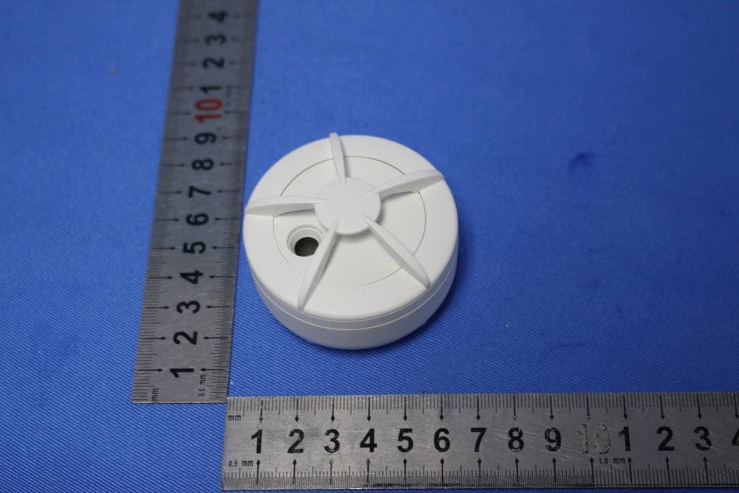
2AHNMFLSZB110
Apr 21, 2020Water Leak Detector
Equipment Class
DTS - Digital Transmission System