2AHV3KK222.4G remote control
Guangdong Meijiaxin Innovative Technology Co., Ltd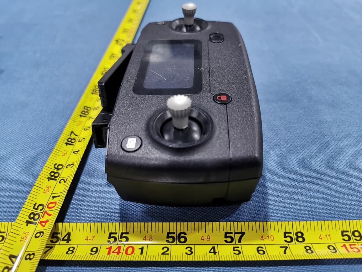
Click to zoom
Application Details
- Equipment Class
- DXX - Part 15 Low Power Communication Device Transmitter
- Date of Grant
- Sep 14, 2020
- Application Purpose
- Original Equipment
- Date of Application
- Sep 14, 2020
- Equipment Note
- 2.4G remote control
- Frequency Range
- 2452.00000000 - 2474.00000000
- Country
- China
Documents & Files
Document Text
Text extracted from the exhibit documents filed with the FCC. Open a document above to read the original.
Users Manual
Bugs 7 User Manual Low battery warning ● If the rear indicator light flash slow, the battery icon in transmitter LCD screen is “ ”. As only the aircraft is beyond 30 meters altitude or 100 meters distance, the aircraft will return home automatically. As long as the aircraft is in 100 meters distance, the user can cancel the return by “ ”. ● When the battery icon “ ” is shown on the LCD screen (Pic. 2) with steady “beep ...beep” sound, it means that the aircraft battery is in low voltage. At this time, the aircraft front lights glow solid on and rear lights flash rapidly. The aircraft will return when the altitude is over 15m or the distance is over 15m; if either the flying altitude or flying distance is less than 15m, the aircraft will land to the ground. Pic. 1Pic. 2 ! Attention: When the aircraft is not inserted with TF card or the TF card is malfunction, photos and videos taking can not be done by pressing the button of the remote controller, but by the icon on the APP interface. One-key takeoff/landing ● After the B7 unlocked, short-press the “ ” button (indicated as below), the aircraft will automatically take off and hover at 1.5m altitude. ● When the aircraft is flying, short-press the “ ” button (indicated as below), the aircraft will automatically land on the ground. In aircraft’s landing automatically, press any joystick, the aircraft will exit the mode. One-key RTH button ● Press the “ ” with the buzzer having “Di”, it means the auto- return home is on. ● The aircraft will return to lasted home point. Press the button shortly again, the return home will be closed. -15- Bugs 7 User Manual Optimal transmission zone To obtain a satisfied flight experience, please make sure that your B7 is flying ahead of the remote controller and no obstacles between the aircraft and the remote controller. Optimal transmission zone Remote control low voltage warning When the “ ” icon appears on the LCD screen and the remote control emits “beep beep” sound, it means that the remote control battery is nearly out of power. Please change new battery for the remote control. Signal strength indicator ● Signal strength bar “ ” shows the strength of the received signal. The more, the better. ● When the strength bar “ ” changes from weak to strong circularly, it means that the remote controller is under signal connection status. ● There are 2 situations that the strength bar “ ” is less than 2 grids or no displaying with steady long beep sounds. 1) The distance between the aircraft and the remote controller is too far causing a weak signal. 2) The battery is removed after the aircraft connects to the remote controller. -16- Bugs 7 User Manual ! Attention: To change the stick mode of the remote controller, please make sure that the remote controller is under signal connection status (the indicator light keep flashing). If not, the stick mode could not be changed. How to change throttle mode Step 1. Keep pressing the red button “ ” and turn on the remote controller, the remote controller is under signal connection status (Pic. 1); Step 2. Keep pressing the RTH button “ ” for 3 seconds to choose the throttle control mode (Pic. 2). The throttle control mode will change according to each press. The mode number is shown on the LCD screen. The throttle control mode is set at mode 2 by default. Pic. 1Pic. 2 Throttle mode switch Mode 1: The right stick serves as the throttle. Mode 2: The left stick serves as the throttle. ● The remote controller is set at Mode 2 by default. Throttle Control Stick Mode Mode 2 (Default) Mode 1 Throttle control Leftward/ Rightward flight control Forward/ Backward control Turn Left/ Right control Throttle control Leftward/ Rightward flight control Forward/ Backward control Turn Left/ Right contro -17- Bugs 7 User Manual Install the Mobile Phone Holder 1. Pull out the mobile phone holder upwards completely (Pic. 1); 2. Tilt the holder 30 degrees towards you and then you will hear a click sound (Pic. 2); 3. Rotate and fix the support board in place (Pic. 3); 4. Adjust the mobile phone holder upward or downward according to the size of your mobile phone (Pic. 4). Pic. 1Pic. 2 Pic. 3Pic. 4 -18- APP Download & Installation This section introduces how to download the “M RC PRO” APP and connect with mobile device. Where to download “M RC PRO” APP ● For Apple IOS system, please turn to Apple store, search “M RC PRO” or scan the QR code at right side to download the software. ● For Android system, please turn to Google play, search “M RC PRO” or scan the QR code at right side to download the software. Or scan “MJXRC. NET” QR code to download the software. FPV Real-time Image Transmission Software “M RC PRO” App Store MJXRC.NET -19- 1. Forbid to fly in following locations, surroundings and scenes. 2. The drone is for 16+ years old, otherwise please play under qualified supervisor. 3. Please comply with local flight laws and regulations, fly reasonably and legally. SkyscraperCrowdsTreesSouth pole & North pole Strong windRainSandstormSnow Base station nearbyHigh voltage wire WatersNo-fly zone Bugs 7 User Manual Setting Wi-Fi Drone4_******* Connect WIFI How to link the “M RC PRO” to the camera Power on the aircraft, then enter phone setting option. Turn on WiFi, find “Drone4_*******” on the list and connect it. When “ ” legend is shown, it means WiFi connection is successful. Exit settings and tap “M RC PRO” APP at your mobile device. Photos and video saving feature 1. If the camera is without TF card, videos and photos will be saved at the APP. (The image definition of video and photo is APP received image quality). 2. If the camera is with TF card, videos and photos will be saved at the TF card. 3. Videos and photos in the TF card can be downloaded to the APP. ! Tips: Only mobile phones that support 5G WIFI (802.11.ac) can make FPV connections. -20- Flight limits and GEO zones Abide by all laws and regulations when flying your B7. Flight limitations are applied by default to help users operate …
Text truncated - open the document above for the full version.
External Photos
FCC ID: 2AHV3KK22 Page 1 of 4 Appendix II: EUT External Photos FCC ID: 2AHV3KK22 Page 2 of 4 FCC ID: 2AHV3KK22 Page 3 of 4 FCC ID: 2AHV3KK22 Page 4 of 4
ID Label/Location Info
Label Location ITEM NO. GR811A FCC ID: 2AHV3KK22 2.4G remote control device MADE IN CHINA
Internal Photos
FCC ID: 2AHV3KK22 Page 1 of 5 Appendix II: EUT Internal Photos FCC ID: 2AHV3KK22 Page 2 of 5 FCC ID: 2AHV3KK22 Page 3 of 5 2.4G Antenna 2.4G Module FCC ID: 2AHV3KK22 Page 4 of 5 FCC ID: 2AHV3KK22 Page 5 of 5
RF Exposure Info
RF Exposure Requirements Product Description: 2.4G remote control Model No.: GR811 FCC ID: 2AHV3KK22 According to the KDB 447498 D01 V06, the following RF exposure evaluation shall to demonstrate RF exposure compliance. General 2.4GHz Technique Tx frequency range: 2452 ~ 2474 MHz Antenna Type: External antenna (Gain: 2.0 dBi) The maximum conducted output power: 0 dBm The maximum radiated output power (e.i.r.p): 2 dBm The maximum radiated emission for the EUT is 80.53dBμV/m at 3m The maximum conducted output power specified is 0 dBm = 1 mW The source- based time-averaging conducted output power = 1 * Duty cycle mW = 0.10 mW (Duty Cycle = 10.4%) The SAR Exclusion Threshold Level: = 3.0 * (min. test separation distance, mm) / sqrt (freq. in GHz) = 3.0 * 5 / sqrt (2.474) mW = 9.54 mW Source-based time-averaged Conducted output power is 0.10 mW < 9.54mW Since the source-based time-averaging conducted output power is well below the SAR low threshold level, so the EUT is considered to comply with SAR requirement without testing.
Test Report
Guangdong Meijiaxin Innovative Technology Co., Ltd. RF TEST REPORT Report Type: FCC Part 15.249 RF report Model: GR811 REPORT NUMBER: 200602836SHA-001 ISSUE DATE: August 19, 2020 DOCUMENT CONTROL NUMBER: TTRF15.249_V1 © 2018 Intertek Intertek Testing Services Shanghai Building No.86, 1198 Qinzhou Road (North) Caohejing Development Zone Shanghai 200233, China Telephone: 86 21 6127 8200 www.intertek.com TEST REPORT This report is for the exclusive use of Intertek's Client and is provided pursuant to the agreement between Intertek and its Client. Intertek's responsibility and liability are limited to the terms and conditions of the agreement. Intertek assumes no liability to any party, other than to the Client in accordance with the agreement, for any loss, expense or damage occasioned by the use of this report. Only the Client is authorized to permit copying or distribution of this report and then only in its entirety. Any use of the Intertek name or one of its marks for the sale or advertisement of the tested material, product or service must first be approved in writing by Intertek. The observations and test results in this report are relevant only to the sample tested. This report by itself does not imply that the material, product, or service is or has ever been under an Intertek certification program. TTRF15.249_V1 © 2018 Intertek Page 2 of 26 Report no.: 200602836SHA-001 Applicant: Guangdong Meijiaxin Innovative Technology Co., Ltd. Address of Applicant: Xingye South Road, Laimei Industrial Park, Chenghai, Shantou, Guangdong, China Manufacturer: Guangdong Meijiaxin Innovative Technology Co., Ltd. Address of Manufacturer: Xingye South Road, Laimei Industrial Park, Chenghai, Shantou, Guangdong, China FCC ID: 2AHV3KK22 SUMMARY: The equipment complies with the requirements according to the following standard(s) or Specification: 47CFR Part 15 (2019): Radio Frequency Devices (Subpart C) ANSI C63.10 (2013): American National Standard of Procedures for Compliance Testing of Unlicensed Wireless Devices PREPARED BY: REVIEWED BY: Project Engineer Wade Zhang Reviewer Daniel Zhao Report No.: 200602836SHA-001 TEST REPORT TTRF15.249_V1 © 2018 Intertek Page 3 of 26 Content REVISION HISTORY................................................................................................................................................ 4 MEASUREMENT RESULT SUMMARY ..................................................................................................................... 5 1 GENERAL INFORMATION ............................................................................................................................. 6 1.1 DESCRIPTION OF EQUIPMENT UNDER TEST (EUT) ..................................................................................................... 6 1.2 TECHNICAL SPECIFICATION .................................................................................................................................... 6 1.3 DESCRIPTION OF TEST FACILITY .............................................................................................................................. 7 2 TEST SPECIFICATIONS ................................................................................................................................... 8 2.1 STANDARDS OR SPECIFICATION ............................................................................................................................... 8 2.2 MODE OF OPERATION DURING THE TEST ................................................................................................................... 8 2.3 TEST PERIPHERALS LIST ......................................................................................................................................... 9 2.4 TEST ENVIRONMENT CONDITION: ............................................................................................................................ 9 2.5 INSTRUMENT LIST ................................................................................................................................................ 9 2.6 MEASUREMENT UNCERTAINTY ............................................................................................................................. 10 3 RADIATED EMISSION ................................................................................................................................. 11 3.1 LIMIT .............................................................................................................................................................. 11 3.2 MEASUREMENT PROCEDURE ............................................................................................................................... 11 3.3 TEST CONFIGURATION ........................................................................................................................................ 13 3.4 TEST RESULTS OF RADIATED EMISSIONS ................................................................................................................. 15 4 POWER LINE CONDUCTED EMISSION ......................................................................................................... 20 4.1 LIMIT .............................................................................................................................................................. 20 4.2 TEST CONFIGURATION ........................................................................................................................................ 20 4.3 MEASUREMENT PROCEDURE ............................................................................................................................... 21 4.4 TEST RESULTS OF POWER LINE CONDUCTED EMISSION............................................................................................... 21 5 ASSIGNED BANDWIDTH (20DB BANDWIDTH) ............................................................................................ 22 5.1 LIMIT ................…
Text truncated - open the document above for the full version.
Test Setup Photos
FCC ID: 2AHV3KK22 Page 1 of 2 Appendix 1: Te s t S e t u p Radiated Emission (Below 1GHz) Radiated Emission (Above 1GHz) FCC ID: 2AHV3KK22 Page 2 of 2 RF Conducted
Contact Information
Applicant
Hellen Lin
Technical Contact
Shenzhen UnionTrust Quality and Technology Co., LtBilly Li
[email protected]0755-28230888
16/F, Block A, Building 6, Baoneng Science and Tec · Shenzhen · China
Non-Technical Contact
Shenzhen UnionTrust Quality and Technology Co., LtBilly Li
[email protected]0755-28230888
Test Firm
Shenzhen UnionTrust Quality and Technology Co., LtGeorge Luo
[email protected]+86-755-28230888
Technical Specifications
| # | Rule Parts | Frequency Range | Power Output |
|---|---|---|---|
| 1 | 15C | 2.45 GHz - 2.47 GHz | - |
Other Applications from Guangdong Meijiaxin Innovative Technology Co., Ltd
2AHV3KK21
Sep 14, 2020R/C drone
Equipment Class
DXX - Part 15 Low Power Communication Device Transmitter
2AHV3KK20
Jan 15, 2020R/C drone
Equipment Class
DXX - Part 15 Low Power Communication Device Transmitter