2AJFX-DDPAIR1SMobile phone rack
DDPAI Technology Co., Ltd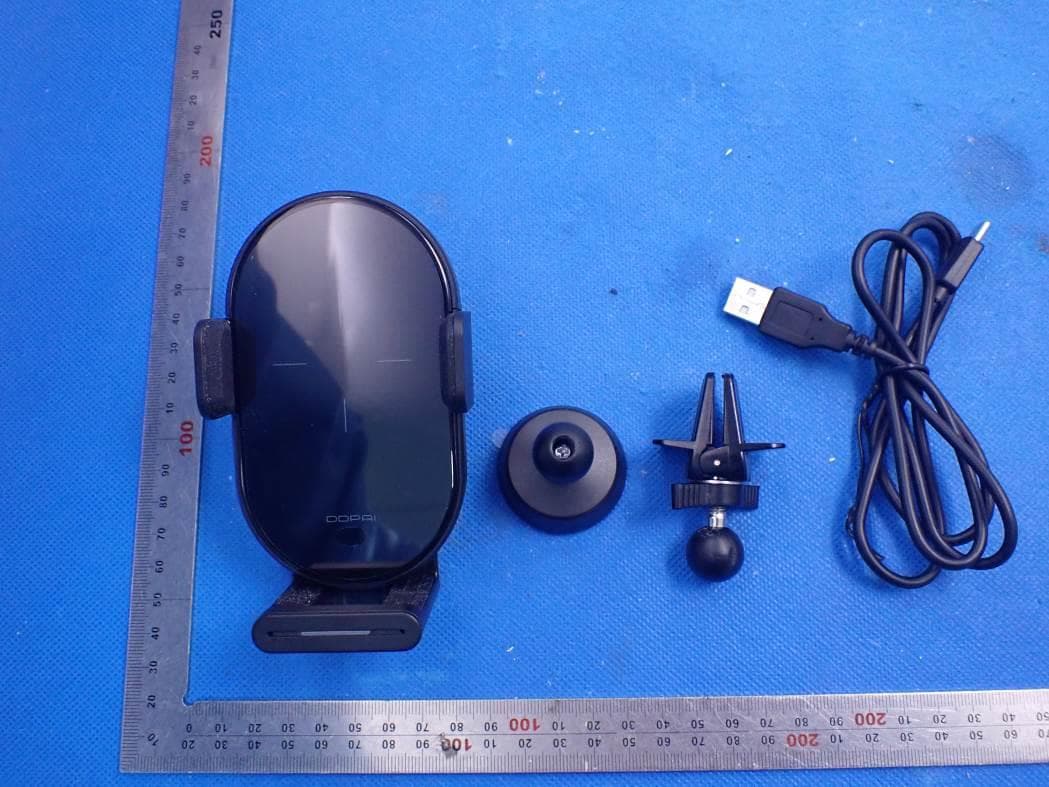
Click to zoom
Application Details
- Equipment Class
- DCD - Part 15 Low Power Transmitter Below 1705 kHz
- Date of Grant
- Mar 08, 2021
- Application Purpose
- Original Equipment
- Date of Application
- Mar 08, 2021
- Equipment Note
- Mobile phone rack
- Frequency Range
- 0.11000000 - 0.20500000
- Company
- DDPAI Technology Co., Ltd
- Country
- China
Documents & Files
Document Text
Text extracted from the exhibit documents filed with the FCC. Open a document above to read the original.
Users Manual
R1S Wireless Fast Charging Car Charger 1.Product Overview Grip Nut Release Button Clamping Arms Wireless Charging Sensing Area Infrared Sensor Indicator Light Adjustable Bottom Tray Type-C Charging Port Note: 1.The bottom tray can be adjusted telescopically to adapt to mobile phones of different sizes and avoid clamping the side buttons; 2.There are safety protective silicone pads on the inside of the arms and the base to better protect the phone. Screw Knob Ball Joint Twist-lock Air Vent Clip 3M glue bracket 2.LED Indicator State of Charging Charging Over Temperature Protection Fault (over voltage / over current / under voltage) Super Capacitor, Power- Off Delay Blue indicator lightening The Blue indicator turns off after 5 seconds The Red indicator Flashes 2-3 times of opening and closing after flameout (within 1 minute), remove your phone by opening it manually without damaging the wireless car charger holder after the car is shut down LED Indicator Display 3.Assembly and Installation Steps The wireless car charger holder can be fixed at the air outlet through the air outlet clip, or fixed on the central control table through 3M glue bracket. Attention: Please adjust the air outlet clip properly, and do not use the air outlet clip too tight. Do not adjust it to the smallest thickness, otherwise it might be damaged. Note: It is recommended that the holder can be fixed at the air outlet firstly. When the air outlet clip is not compatible with the air outlet, then use 3M glue bracket to fix it. Open I. Tight 0.24inch-0.39inch II. Tighter 0.12inch-0.24inch III. Tightest 0inch-0.12inch Tighter Method 1- Using with the air outlet clip Step 1. Unscrew the grip nut from the holder and remove it. Step 2. Pass the ball joint through the grip nut from the smaller opening side. Step 4. Find a suitable place in your automobile outlet, insert the holder. Adjust the angle of the holder to fit the sight line. Step 3. Push the ball joint firmly into the groove on the back of the holder, then tighten clockwise the grip nut. Step 2. Confirm that the universal ball joint is installed in place, and tighten the nut clockwise. Step 3. Wipe the position where the holder needs to be placed to ensure that it is clean and flat. Step 4. Tear off the 3M glue at the bottom of the 3M glue bracket base; paste the 3M glue bracket at the wiped position and adjust the angle of the holder to fit the sight line. Step 1. Take out the 3M glue bracket and then press the universal ball head of 3M glue bracket into the nut. Method 2- Using with the 3M glue bracket 4.Switch on Power Supply, Wireless Charging Step 1. Plug the car charger into the car’s cigarette lighter base ( Note: The car charger is not included in the package). Step 2. Plug the charging cable USB connector into the car charger. Insert the charging cable Type-C connector into the charging port of the holder to turn on the power. Step 3. Put the phone into the holder, then the clamping arms will grip the phone automatically and the wireless charging will start in a few second. The indicator light will always turn blue. The holder supports 9V/2A and 12V/1.5A car chargers. The use of 5V/2A, 5V/1A and 5V/0.5A car chargers with low power will cause the device to work abnormally or charge efficiency low. Note: Please adjust the adjustable bottom tray to adapt to mobile phones of different sizes. Step 1. After the holder is power on, when the mobile phone is close to the holder, the clamping arms on both sides of the holder will automatically open, and automatically close after about two seconds. Step 2. When taking out the phone from the holder, touch the release button on the side of the holder with your finger, and the clamping arm will open automatically. √ × × 1) Do not place your fingers in the horizontal direction of the clamping arm to avoid getting hurt. 2) Ensure that there is no metal foreign matter between the wireless charging surface and the phone and no metal inside or outside the protective case. Attention: 5.Instruction of Auto Clamping Arms The wireless car charger holder supports automatic induction recognition. Intelligent sensor allows to pick & place it quickly. Just place your phone , the clamping arms will close. A gentle touch on quick release button, it would open automatically. 6.FCC STATEMENT This device complies with Part 15 of the FCC Rules. Operation is subject to the following two conditions: (1)This device may not cause harmful interference. (2)This device must accept any interference received, including interference that may cause undesired operation. Warning: Changes or modifications not expressly approved by the party responsible for compliance could void the user's authority to operate the equipment. NOTE: This equipment has been tested and found to comply with the limits for a Class B digital device, pursuant to Part 15 of the FCC Rules. These limits are designed to provide reasonable protection against harmful interference in a residential installation. This equipment generates uses and can radiate radio frequency energy and, if not installed and used in accordance with the instructions, may cause harmful interference to radio communications. However, there is no guarantee that interference will not occur in a particular installation. If this equipment does cause harmful interference to radio or television reception, which can be determined by turning the equipment off and on, the user is encouraged to try to correct the interference by one or more of the following measures: RF warning statement: FCC Radiation Exposure Statement: The device has been evaluated to meet general RF exposure requirement. The device can be used in portable exposure condition without restriction. This equipment complies with FCC radiation exposure limits set forth for an uncontrolled environment. This equipment should be installed and operated with minimum distance 20cm between the radiator & your body. Reorient or relocate the receiving antenna. Incr…
Text truncated - open the document above for the full version.
External Photos
External Photos ALL VIEW OF EUT TOP VIEW OF EUT BOTTOM VIEW OF EUT FRONT VIEW OF EUT BACK VIEW OF EUT LEFT VIEW OF EUT RIGHT VIEW OF EUT VIEW OF EUT (PORT)-1
ID Label/Location Info
FCC ID Label Location FCC ID: 2AJFX-DDPAIR1S
Internal Photos
Internal Photos OPEN VIEW OF EUT INTERNAL VIEW OF EUT-1 INTERNAL VIEW OF EUT-2 INTERNAL VIEW OF EUT-3 INTERNAL VIEW OF EUT-4 INTERNAL VIEW OF EUT-5 Coil Antenna
Operational Description
DDPAI Technology Co., Ltd Declaration concerning Antenna Specification It is hereby declared that the product Model No.: DDPAI R1S FCC ID: 2AJFX-DDPAIR1S fulfills the requirement in FCC test relating to the antenna type. The device specified above confirms to the FCC recommendations for internal antenna type(s) described below: Type of antenna: Coil Antenna Frequency range: 110-205kHz The mounting of the antenna is fixed to the radio module and no other antenna should be used. Company name: DDPAI Technology Co., Ltd Address: Floor 12,Yihua finance building, Nanshan software industry park, Xuefu Rd, Nanshan district, Shenzhen, China Date: 2021-03-09 Signature:
RF Exposure Info
Page 1 of 14 RF Exposure Report Report No.: AGC05414201202FH03 APPLICATION PURPOSE : Original Equipment PRODUCT DESIGNATION : Mobile phone rack BRAND NAME : DDPAI MODEL NAME : DDPAI R1S APPLICANT : DDPAI Technology Co., Ltd DATE OF ISSUE : Jan. 30, 2021 STANDARD(S) : KDB680106 D01 RF Exposure Wireless Charging Base App v03 REPORT VERSION : V1.0 Attestation of Global Compliance (Shenzhen) Co., Ltd Report No.: AGC05414201202FH03 Page 2 of 14 REPORT REVISE RECORD Report Version Revise Time Issued Date Valid Version Notes V1.0 / Jan. 30, 2021 Valid Initial Release Report No.: AGC05414201202FH03 Page 3 of 14 TABLE OF CONTENTS 1. VERIFICATION OF CONFORMITY ............................................................................................................... 4 2. GENERAL INFORMATION ............................................................................................................................ 5 2.1. PRODUCT DESCRIPTION ..................................................................................................................... 5 3. DESCRIPTION OF TEST MODES................................................................................................................. 6 4. SYSTEM TEST CONFIGURATION ............................................................................................................... 6 5. TEST FACILITY ............................................................................................................................................. 7 6. RADIO FREQUENCY (RF) EXPOSURE TEST ............................................................................................. 8 6.1. LIMITS ..................................................................................................................................................... 8 6.2. TEST SETUP ........................................................................................................................................... 8 APPENDIX A: PHOTOGRAPHS OF TEST SETUP ......................................................................................... 11 Report No.: AGC05414201202FH03 Page 4 of 14 1. VERIFICATION OF CONFORMITY Applicant DDPAI Technology Co., Ltd Address Floor 12,Yihua finance building, Nanshan software industry park, Xuefu Rd, Nanshan district, Shenzhen, China Manufacturer DDPAI Technology Co., Ltd Address Floor 12,Yihua finance building, Nanshan software industry park, Xuefu Rd, Nanshan district, Shenzhen, China Factory DDPai vision equipment Co., Ltd Address Building A, Futai Industrial Park, Qingfeng south Road, Keyuancheng, Tangxia Town, Dongguan city, Guangdong province, China Product Designation Mobile phone rack Sample No 201225127 Brand Name DDPAI Test Model: DDPAI R1S Date of test Dec. 30, 2020 to Jan. 30, 2021 Deviation No any deviation from the test method Condition of Test Sample Normal Report Template AGCRT-US-BR/RF We hereby certify that: The above equipment was tested by Attestation of Global Compliance (Shenzhen) Co., Ltd. The test data, data evaluation, test procedures, and equipment configurations shown in this report were made in accordance with the procedures given in KDB680106 D01. The results of testing in this report apply to the product/system which was tested only. Prepared By Sky Dong (Project Engineer) Jan. 30 2021 Reviewed By Max Zhang (Reviewer) Jan. 30, 2021 Approved By Forrest Lei (Authorized Officer) Jan. 30, 2021 Report No.: AGC05414201202FH03 Page 5 of 14 2. GENERAL INFORMATION 2.1. PRODUCT DESCRIPTION A major technical description of EUT is described as following Operation Frequency 110KHz-205KHz Test Frequency 145kHz/153kHz/161kHz Maximum field strength 52.78dBuV/m(PK)@3m Number of channels 1 Antenna Designation Coil Antenna (Met 15.203 Antenna requirement) Hardware Version V1.2 Software Version V0.0.0.1 Power Supply(Input) DC 9V, 2A, DC 12V, 1.5A Wireless Charging Output power 15W(Max) Report No.: AGC05414201202FH03 Page 6 of 14 3. DESCRIPTION OF TEST MODES NO. TEST MODE DESCRIPTION 1 Wireless charging Mode(Full load) 2 Wireless charging Mode(Half load) 3 Wireless charging Mode(Null load) Note: 1. The mode 1 was the worst case and only the data of the worst case record in this report. 4. SYSTEM TEST CONFIGURATION Item Equipment Model No. ID or Specification Remark 1 Mobile phone rack DDPAI R1S 2AJFX-DDPAIR1S EUT 2 Wireless Load N/A 15W AE Report No.: AGC05414201202FH03 Page 7 of 14 5. TEST FACILITY TEST EQUIPMENT LIST Description Manufacturer Model S/N Cal. Date Cal. Due Broadband Field Meter Narda Safety Test Solutions GmbH ELT-400 J-0004 May 25,2020 May 24,2021 Probe FHP Narda Safety Test Solutions GmbH 2300/90.10 J-0015 May 25,2020 May 24,2021 TestSite Attestation of Global Compliance(Shenzhen) Co., Ltd Location 1-2/F,Building19,JunfengIndustrialPark,ChongqingRoad,HepingCommunity,FuhaiSt reet,Bao'anDistrict,Shenzhen,Guangdong,China Designation Number CN1259 FCC Test Firm Registration Number 975832 A2LA Cert. No. 5054.02 Description Attestation of Global Compliance(Shenzhen) Co., Ltd is accredited by A2LA Report No.: AGC05414201202FH03 Page 8 of 14 6. RADIO FREQUENCY(RF) EXPOSURETEST 6.1. LIMITS For devices designed for typical desktop applications, such a wireless charging pads, RF exposure evaluation should be conducted assuming a user separation distance of 15 cm. E and H field strength measurements or numerical modeling may be used to demonstrate compliance. Measurements should be made from all sides and the top of the primary/client pair, with the 15 cm measured from the center of the probe(s) to the edge of the device. Emissions between 100 kHz to 300 kHz should be assessed versus the limits at 300 kHz in Table 1 of Section 1.1310: 614 V/m and 1.63 A/m. 6.2. TEST SETUP Note: Position A: Front of EUT; Position B: Left of EUT; Position C: back of EUT; Position D: Right of EUT; Position E: Top of EUT(20 cm measure distance); Report No.: AGC05414201202FH03 Page 9 of 14 6.3. TEST PROCEDURE The EUT was placed on a non-co…
Text truncated - open the document above for the full version.
Test Report
Page 1 of 25 FCC Test Report Report No.: AGC05414201202FE04 FCC ID : 2AJFX-DDPAIR1S APPLICATION PURPOSE : Original Equipment PRODUCT DESIGNATION : Mobile phone rack BRAND NAME : DDPAI MODEL NAME : DDPAI R1S APPLICANT : DDPAI Technology Co., Ltd DATE OF ISSUE : Jan. 30, 2021 STANDARD(S) TEST PROCEDURE(S) : FCC Part 15 Rules REPORT VERSION : V1.0 Attestation of Global Compliance (Shenzhen) Co., Ltd Report No.: AGC05414201202FE04 Page 2 of 25 REPORT REVISE RECORD Report Version Revise Time Issued Date Valid Version Notes V1.0 / Jan. 30, 2021 Valid Initial Release Report No.: AGC05414201202FE04 Page 3 of 25 TABLE OF CONTENTS 1. VERIFICATION OF CONFORMITY ............................................................................................................................. 4 2. GENERAL INFORMATION .......................................................................................................................................... 5 2.1. PRODUCT DESCRIPTION ....................................................................................................................................................... 5 3. MEASUREMENT UNCERTAINTY .............................................................................................................................. 6 4. DESCRIPTION OF TEST MODES .............................................................................................................................. 7 5. SYSTEM TEST CONFIGURATION ............................................................................................................................. 8 5.1. CONFIGURATION OF EUT SYSTEM ........................................................................................................................................ 8 5.2. EQUIPMENT USED IN EUT SYSTEM ...................................................................................................................................... 8 5.3. SUMMARY OF TEST RESULTS ................................................................................................................................................ 8 6. TEST FACILITY ............................................................................................................................................................ 9 7. RADIATED EMISSION ............................................................................................................................................... 10 7.1TEST LIMIT ........................................................................................................................................................................... 10 7.2. MEASUREMENT PROCEDURE ............................................................................................................................................ 11 7.3. TEST SETUP ........................................................................................................................................................................ 12 7.4. TEST RESULT ....................................................................................................................................................................... 13 8. 20DB BANDWIDTH ................................................................................................................................................... 16 8.1. MEASUREMENT PROCEDURE ............................................................................................................................................ 16 8.2. TEST SET-UP (BLOCK DIAGRAM OF CONFIGURATION) ........................................................................................................ 16 8.3. MEASUREMENT RESULTS ................................................................................................................................................... 17 APPENDIX A: PHOTOGRAPHS OF TEST SETUP ..................................................................................................... 18 APPENDIX B: PHOTOGRAPHS OF EUT .................................................................................................................... 19 Report No.: AGC05414201202FE04 Page 4 of 25 1. VERIFICATION OF CONFORMITY Applicant DDPAI Technology Co., Ltd Address Floor 12,Yihua finance building, Nanshan software industry park, Xuefu Rd, Nanshan district, Shenzhen, China Manufacturer DDPAI Technology Co., Ltd Address Floor 12,Yihua finance building, Nanshan software industry park, Xuefu Rd, Nanshan district, Shenzhen, China Factory DDPai vision equipment Co., Ltd Address Building A, Futai Industrial Park, Qingfeng south Road, Keyuancheng, Tangxia Town, Dongguan city, Guangdong province, China Product Designation Mobile phone rack Sample No 201225127 Brand Name DDPAI Test Model DDPAI R1S Date of test Dec. 30, 2020 to Jan. 30, 2021 Deviation No any deviation from the test method Condition of Test Sample Normal Test Result Pass Report Template AGCRT-US-BR/RF We hereby certify that: The above equipment was tested by Attestation of Global Compliance (Shenzhen) Co., Ltd. The test data, data evaluation, test procedures, and equipment configurations shown in this report were made in accordance with the procedures given in ANSI C63.10 (2013) and the energy emitted by the sample EUT tested as described in this report is in compliance with Section 15.207, 15.209, 15.203 of the FCC Part 15, Subpart C Rules. The results of testing in this report apply to the product/system which was tested only. Prepared By Sky Dong (Project Engineer) Jan. 30 2021 Reviewed By Max Zhang (Reviewer) Jan. 30, 2021 Approved By Forrest Lei (Authorized Officer) Jan. 30, 2021 Report No.: AGC05414201202FE04 Page 5 of 25 2. GENERAL INFORMATION 2.1. PRODUCT DESCRIPTION A major technical description of EUT is described as following Operation Frequency 110KHz-205KHz Test Frequency 145kHz Maximum field strength 52.78dBuV/m(PK)@3m Modulation FSK Number of channels 1 Antenna Designation Coi…
Text truncated - open the document above for the full version.
Test Setup Photos
Test Setup Photos FCC RADIATED EMISSION TEST SETUP BELOW 1GHZ
Contact Information
Applicant
Sean Yu(Certification Engineer)
Test Firm
Attestation of Global Compliance (Shenzhen) Co., LDoris Li
[email protected]+86-755-25234088
Technical Specifications
| # | Rule Parts | Frequency Range | Power Output |
|---|---|---|---|
| 1 | 15C | 0.11 MHz - 0.205 MHz | - |
Other Applications from DDPAI Technology Co., Ltd
2AJFX-DE001
Aug 28, 2026Dash Cam
Equipment Class
DTS - Digital Transmission System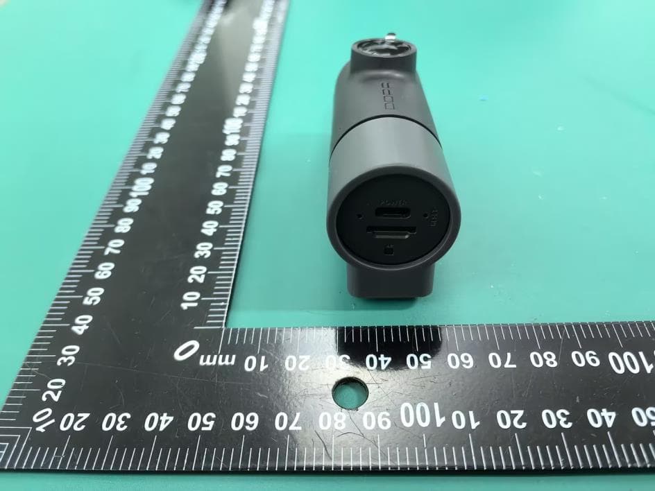
2AJFX-DM2505A
Aug 27, 2026Dash Cam
Equipment Class
NII - Unlicensed National Information Infrastructure TX2AJFX-DN2602
Aug 19, 2026Dash Cam
Equipment Class
DTS - Digital Transmission System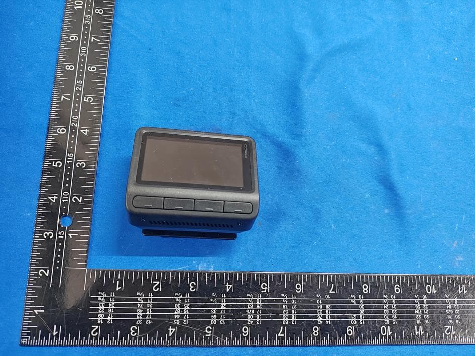
2AJFX-DZ2502
Jul 28, 2026Dash Cam
Equipment Class
DTS - Digital Transmission System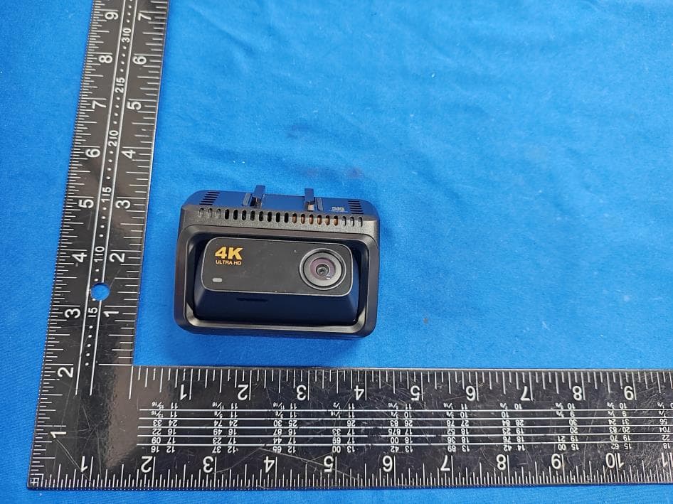
2AJFX-DZ2501A
Apr 17, 2026Dash Cam
Equipment Class
DTS - Digital Transmission System