2AJFX-MINI5DDPai
DDPAI Technology Co., Ltd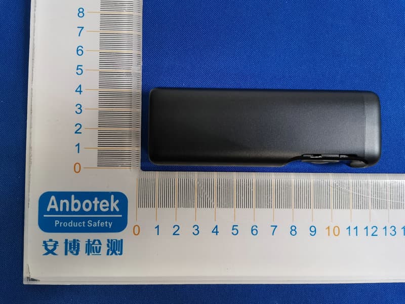
Click to zoom
Application Details
- Equipment Class
- NII - Unlicensed National Information Infrastructure TX
- Date of Grant
- Aug 13, 2020
- Application Purpose
- Original Equipment
- Date of Application
- Aug 13, 2020
- Equipment Note
- DDPai
- Frequency Range
- 5180.00000000 - 5240.00000000
- Company
- DDPAI Technology Co., Ltd
- Country
- China
Documents & Files
Document Text
Text extracted from the exhibit documents filed with the FCC. Open a document above to read the original.
Users Manual
亡3已仁仁l 0 PACKAGE CONTENTS 日PRODUCTOVERVIEW 日INSTALLATION 5, After the ca『 sta『ts,the Dash Cam powe『sup ancl starts『ecording. , , , - . . ;-- =,· ` 、 今 ,_:hL1 笠 -: ·· -- ::: ,: 令. . 还 ( , - ,·C - 士寸 I :,,,____..,�':'1 \<'c 一一 名 、 - - ·· { 、 I T · r � Working lnd1cato『 MIC ( Second on the left ) 气 卞》. u,必 i . 这 二 多 \5 、 7}名 飞、名一一 、 j- 』. ',一 一 丈卜 t'. ,«4 ',L,` , . 仁 一 • I Bracket ` - . , 二」 L— ',一 , / — 三 L ens MINIS 今, / / / / / / . 尸 , (. / / / ,;;, 芩·- 五 : 气·- - - - 勹 ; i _ - - -.·,, ,,;;: 己 : . . . 一_ _ .. , , -- — ->. 妘_., / ,- - - 、 、 、 (.' ',\ 气 ` Type-C Interlace (一 一、 ' · , .. 3M Adhesive Button 1. Clean the area on the w1nclsh1elcl where the Dash Cam will be install的 , otherwiseit may fall off easily in later. 2. Gently push the Dash Cam into the bracket, which can be fixed tJy a magnet insicle the bottom of the bracket. r - - - " \. 入 飞, • - - - I 立 亡,, - -:: 气 ;;: : 良 勹 、习 - - - ,立 3. Remove the protective film from the back of the bracl<et, attach the adhesive side of the mount on the windshield where it has an unobstructed view of the road but does not interfere with the driver's view. As shown below. � \ , 飞 ,.,. 二 二 气 - -- ;,, c员 -=:j t - 1 0 闱 - "" q \. I' ,J ` l_ 八夕' l 荔.L' i 3、.`` ' ,. . . . - , }.夕 叉”,-__ f,' .. . }· .\ ' ,r. ` . . . -- . . - , ' _ _ r . , . //- -,- .l- \ / ., ', _ 4. Use the installation tool to lift the edges of the windshield /molding and tuck in the power cable Connect the Dash Cam to 1he ca『 cha『ger{plugged into cigarette lighter socket) and power cable 口INDICATORAND BUTTON Name Work Indicator Button Description Normal recording: Blue light Is always on. Parking monitoring: Rad light Is always on. Upgrading/coll心ion/Takingpie Lures by voice: Purple Ilg ht flashes qulckly. USB data transmission mode: Green light is always on. Storage error: Green light flashes quickly It does not support powe『on or oll Turn on/off recording: Click the button to turn on/oif recording Reset: Long press 6s to reset 日INSTALLDDF>AI APP For Android/ IOS phones, search for "DDPAI" In the Google Play Store or Apple App Store. Download the App and install it on your phone. Note: In orcler to connect to camera W1-Fi, please list the App in your trus1 application list and make sure the camera's Wi-Fi is on. 田APPINSTRUCTION 6.1 On the Road DDPAI users community, from here you can find nearby users, see the newest activities, user experience, 1ns1a11alion tutorial etc. 心母。 了; 烹义[ Road ! Al b u ms Me Soc a l Media Shanng 6.2 Camera 仑吓口 恳产 。 rr=: ii, Add camera 1rom here. Pair Smart Phone to Dash Cam 1) Launch DDPAI App. tap on camera, then tap on+. 2) Choose your DDPAI Dash Cam from the network 11st (For Androici system. App will start to search Dash Cam network automa11ca11y. For 10S phone: turn on W L AN from "Settings ->WLAN•) . The Dash Cam's default SSID (orWi-FI name) IS DDPAl_mola MINl5_XXXX 3) Enter the password (the default password is '1234567890'). 4) Click ADD CAMERA, wait a tew seconds until the preview screen show Preview/ Playback Connect to Dash Cam via direct Wi-Fi, to see recen1 videos and『eal-timedisplay, 1) Open the DDPAI App, and add your Dash Cam. 2) Select Camera tab, then tap on 0 button. this will bring you to preview page Downloac p,,,, •• 俨 · 、 ` ` . , 。 • Shutter button •Turn lo landscape mode Rotate your smart phone or press expand & icon, turn preview screen to landscape mode. Aspect ratio Resolution settln� Download T i m巳line bar Playback: Tap and left/right drag timeline bar at the scraen oottom to create the starting point of the recording you wish to preview, then tap on thumbnail when you have made your selection, or wait far 5 sec for buffering, now you can watch the history recording Download Images and Videos Tap on O from preview screen 』 youcan select image or video to download. Download image files: Download manually tly: Taping on download image files from preview screen, this wil I bring you to ciownloaci page, you can select or just simply tap on the images which you want to download. The image files can be downloaded automatically by: Going into·'Me-> Settings" , turn on·Capture files auto download" . Download video flies: 1 .Select download video files from preview screen. 2.Drag time line bar to create the starting point 3.Tap on download icon e to start download. 4.Tap on finish icon O when you have made your selection 6.3 Social Media Sharing ee 。 Taping on O Icon to share picture, video on social media like Faceoook, Twitter etc, 6.4 Album '"'"' ,a�, ,m, 『a虾勺 _c View Images, videos ancl emergency clips, you also can edit and share them from here -,怎O巨丛 6.5 Me Senings, heir:, center and about us. Satti ngs: From hare you can se1 Dash Cam's name and passworcl, camera volume, 『esolution,G-Sensor sensitivity, parking mocle, format sci care:!, and so on. Help: How to use the Dash Cam About: Update firmware, contact us, information about the Dash Cam. 日 UPG旺DE APP AND FIRMWARE Update via App: If a new version of the fi『mware is release cl, opening the App wlll prompt you to download it. You can also open the staring App, enter'Me-> About " , click to d etect the new version, the App will automalically download and upg racie Upgrade via PC: Access your Dash Cam via PC with USB data cable, Download the latest firmware for your camera, unzip and copy the content you have unzipped onto the build-in memory.Power on the camera and it will apply the fl『mware automatically NOTE : Do not power o「I your Dash Cam unlil il begins con linuous recnrdlng os II may r.auso pormanont dam刁go to tho Das h Cam. 日 SPECIFICATIONS CPU, H.265 hardware encoding,HiS山con processor Wi-Fi : Wi-Fi/ 5GHz G-Sensor: Built-in 6 Gyro senso『, motion locking, ad」ustable sens1t1vity via App Storage: Built 一 in eMMC high speed flash, loop recorcling Video Output: Wireless video output, support Androld/lOS cl evlce Lens: 140"wide angle, F1 . 8 Image Sensor: BMP CMOS sensor Image Resolution: 3840•21 eo Video Resolution: Output 3840 全 2160, Preview , 2so•120 R AM: 4Gb Elec…
Text truncated - open the document above for the full version.
External Photos
FCC ID: 2AJFX-MINI5
ID Label/Location Info
Label Location On EUT Label Product Name: DDPai Model No.: MINI5 FCC ID: 2AJFX-MINI5 This device complies with Part 15 of the FCC Rules. Operation is subject to the following two conditions: (1) This device may not cause harmful interference, and (2)This device must accept any interference received, including interference that may cause undesired operation.
Internal Photos
FCC ID: 2AJFX-MINI5 WiFi ANT AWiFi ANT B BT ANT
Operational Description
version01 DDPAI Technology Co., Ltd Declaration concerning Antenna Specification It is hereby declared that the product Model No.: MINI5, MINI5 Pro FCC ID : 2AJFX-MINI5 fulfills the requirement in FCC test relating to the antenna type. The device specified above confirms to the FCC recommendations for internal antenna type(s) described below: BT: Model No. of antenna: ZTX-MINI5-BT-A2 Type of antenna:PIFA Antenna Gain of the antenna: 2 dBi Frequency range:2402-2480MHz WiFi: Model No. of antenna: ZTX-MINI5-WIFI2-A3 & ZTX-MINI5-WIFI1-A3 Type of antenna:PIFA Antenna Gain of the antenna: 2 dBi Frequency range:5180MHz~5240MHz The mounting of the antenna is fixed to the radio module and no other antenna should be used. Company name: DDPAI Technology Co., Ltd Address: Floor 12, Yihua Finance Building, Nanshan Software Industry park, Xuefu Rd, Nanshan District, Shenzhen, China City:Shenzhen ZIP / Postal code: N/A Country:China Place:ChinaDate: 2020-08-11 Signature:
RF Exposure Info
RF EXPOSURE EVALUATION According to FCC 1.1310: The criteria listed in the following table shall be used to evaluate the environment impact of human exposure to radio frequency(RF) Radiation as specified in §1.1307(b) FCC ID: 2AJFX-MINI5 EUT Specification EUTDDPai Frequency band (Operating) WLAN: 2.412GHz ~ 2.462GHz WLAN: 5.18GHz ~ 5.24GHz WLAN: 5.745GHz ~ 5.825GHz Others: 2.402GHz~2.480GHz Device category Portable (<20cm separation) Mobile (>20cm separation) Others ___ Exposure classificationOccupational/Controlled exposure (S = 5mW/cm2) General Population/Uncontrolled exposure (S=1mW/cm2) Antenna diversitySingle antenna Multiple antennas Tx diversity Rx diversity Tx/Rx diversity Max. output powerBLE: 5.416dBm (0.0035W) BDR&EDR: 7.433dBm (0.0055W) 5.1GWiFi: 16.11dBm (0.0408W) Antenna gain (Max)BT & WiFi: 2dBi Evaluation appliedMPE Evaluation SAR Evaluation Limits for Maximum Permissible Exposure(MPE) Frequency Range(MHz) Electric Field Strength(V/m) Magnetic Field Strength(A/m) Power Density(mW/cm 2 ) Average Time (A) Limits for Occupational/Control Exposures 300-1500----F/3006 1500-100000----56 (B) Limits for General Population/Uncontrol Exposures 300-1500----F/15006 1500-100000----130 Friis transmission formula: Pd=(Pout*G)\(4*pi*R2) Where Pd= Power density in mW/cm 2 Pout=output power to antenna in Mw G= gain of antenna in linear scale Pi=3.1416 R= distance between observation point and center of the radiator in cm Pd the limit of MPE, 1mW/cm2. If we know the maximum gain of the antenna and total power input to the antenna, through the calculation, we will know the distance where the MPE limit is reached. Measurement Result 5.1GHz WiFi: ANT A: Operating Mode Channel Frequency Measured Power Tune up tolerance Max. Tune up Power Antenna Gain Power density at 20cm Power density Limits (mW/cm2 ) (MHz)(dBm)(dBm)(dBm)(dBi)(mW/ cm2 ) 802.11a 518013.5613.56 ± 114.5620.00901 520011.8711.87 ± 112.8720.00611 524014.0614.06±115.0620.01011 802.11n20 518012.6012.60 ± 113.620.00721 520010.6910.69 ± 111.6920.00471 524011.3211.32±112.3220.00541 802.11ac20 518012.4612.46 ± 113.4620.00701 520011.4811.48 ± 112.4820.00561 524011.4311.43±112.4320.00551 802.11n40 519012.3112.31 ± 113.3120.00681 523012.8212.82 ± 113.8220.00761 802.11ac40 519012.1812.18±113.1820.00661 523012.3712.37 ± 113.3720.00691 802.11ac80 521013.0713.07 ± 114.0720.00801 ANT B: ANT A+ANT B: Operating Mode Channel Frequency Measured Power Tune up tolerance Max. Tune up Power Antenna Gain Power density at 20cm Power density Limits (mW/cm2 ) (MHz)(dBm)(dBm)(dBm)(dBi)(mW/ cm2 ) 802.11a 518013.1113.11±114.1120.00811 520011.8011.80 ± 112.820.00601 524012.1412.14 ± 113.1420.00651 802.11n20 518013.0213.02±114.0220.00801 520012.3912.39 ± 113.3920.00691 524011.5711.57 ± 112.5720.00571 802.11ac20 518011.6211.62±112.6220.00581 520011.6011.60 ± 112.620.00571 524011.3511.35 ± 112.3520.00541 802.11n40 519013.4813.48±114.4820.00881 523011.9511.95 ± 112.9520.00621 802.11ac40 519012.8612.86 ± 113.8620.00771 523011.8511.85±112.8520.00611 802.11ac80 521013.1313.13 ± 114.1320.00821 Operating Mode Channel Frequency ANT A Power density at 20cm ANT B Power density at 20cm ANT A+ANT B Power density at 20cm Power density Limits (MHz)(mW/ cm2 )(mW/ cm2 )(mW/ cm2 )(mW/cm2 ) 802.11n20 51800.00720.00800.01521 5200 0.00470.00690.0116 1 5240 0.00540.00570.0111 1 802.11ac20 51800.00700.00580.01281 5200 0.00560.00570.0113 1 5240 0.00550.00540.0109 1 802.11n40 51900.00680.00880.01561 5230 0.00760.00620.0138 1 802.11ac40 5190 0.00660.00770.0143 1 52300.00690.00610.01301 802.11ac80 5210 0.00800.00820.0162 1 BEL&BDR+EDR: Operating Mode Channel Frequency (MHz) Measured Power (dBm) Tune up tolerance (dBm) Max. Tune up Power (dBm) Antenna Gain (dBi) Power density at 20cm (mW/ cm 2 ) Power density Limits (mW/cm 2 ) BLE 24025.1675.167±16.16720.00131 24405.3585.358±16.35820.00141 24805.4165.416±16.41620.00141 BDR&E DR 24025.1015.101±16.1012 0.0013 1 24415.2525.252±16.25220.00131 24805.3695.369±16.36920.00141 24027.1247.124±18.12420.00201 24417.3927.392±18.39220.00221 24807.4337.433±18.43320.00221 Note: BT and WIFI cannot support simultaneous transmission.
Test Report
Report No.: 18220WC00098803FCC ID: 2AJFX-MINI5Page 1 of 92 Code:AB-RF-05-a FCC Test Report Client Name: DDPAI Technology Co., Ltd Address: Floor 12, Yihua Finance Building, Nanshan Software Industry park, Xuefu Rd, Nanshan District, Shenzhen, China Product Name: DDPai Date: Aug. 10, 2020 Shenzhen Anbotek Compliance Laboratory Limited Report No.: 18220WC00098803FCC ID: 2AJFX-MINI5Page 2 of 92 Code:AB-RF-05-a Contents 1. General Information ............................................................................................................................................... 4 1.1. Client Information ....................................................................................................................................... 4 1.2. Description of Device (EUT) ..................................................................................................................... 4 1.3. Auxiliary Equipment Used During Test ................................................................................................... 5 1.4. Description of Test Modes ........................................................................................................................ 5 1.5. List of channels ........................................................................................................................................... 6 1.6. Description Of Test Setup ......................................................................................................................... 7 1.7. Test Equipment List .................................................................................................................................... 8 1.8. Measurement Uncertainty ......................................................................................................................... 9 1.9. Description of Test Facility ........................................................................................................................ 9 2. Summary of Test Results ................................................................................................................................... 10 3. Conducted Emission Test ................................................................................................................................... 11 3.1. Test Standard and Limit .......................................................................................................................... 11 3.2. Test Setup .................................................................................................................................................. 11 3.3. Test Procedure .......................................................................................................................................... 11 3.4. Test Data .................................................................................................................................................... 11 4. Radiation Spurious Emission and Band Edge ................................................................................................ 16 4.1. Test Standard and Limit .......................................................................................................................... 16 4.2. Test Setup .................................................................................................................................................. 16 4.3. Test Procedure .......................................................................................................................................... 17 4.4. Test Data .................................................................................................................................................... 18 5. Maximum Peak Output Power Test .................................................................................................................. 51 5.1. Test Standard and Limit .......................................................................................................................... 51 5.2. Test Setup .................................................................................................................................................. 51 5.3. Test Procedure .......................................................................................................................................... 51 5.4. Test Data .................................................................................................................................................... 51 6. Occupy Bandwidth Test ...................................................................................................................................... 55 6.1. Test Standard ............................................................................................................................................ 55 6.2. Test Setup .................................................................................................................................................. 55 6.3. Test Procedure .......................................................................................................................................... 55 6.4. Test Data .................................................................................................................................................... 55 7. Power Spectral Density Test .............................................................................................................................. 72 7.1. Test Standard and Limit .......................................................................................................................... 72 7.2. Test Setup .................................................................................................................................................. 72 7.3. Test Procedure ...................................................................................................................…
Text truncated - open the document above for the full version.
Test Setup Photos
FCC ID: 2AJFX-MINI5 Photo of Conducted Emission Measurement Photo of Radiation Emission Test
Contact Information
Applicant
Sean Yu(Certification Engineer)
Test Firm
Shenzhen Anbotek Compliance Laboratory LimitedJeff Zhu
Technical Specifications
| # | Rule Parts | Frequency Range | Power Output |
|---|---|---|---|
| 1 | 15E | 5.18 GHz - 5.24 GHz | 40.90 mW |
Other Applications from DDPAI Technology Co., Ltd
2AJFX-DE001
Aug 28, 2026Dash Cam
Equipment Class
DTS - Digital Transmission System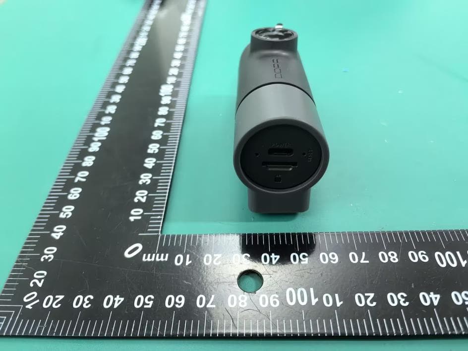
2AJFX-DM2505A
Aug 27, 2026Dash Cam
Equipment Class
NII - Unlicensed National Information Infrastructure TX2AJFX-DN2602
Aug 19, 2026Dash Cam
Equipment Class
DTS - Digital Transmission System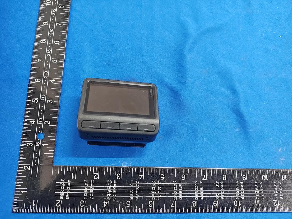
2AJFX-DZ2502
Jul 28, 2026Dash Cam
Equipment Class
DTS - Digital Transmission System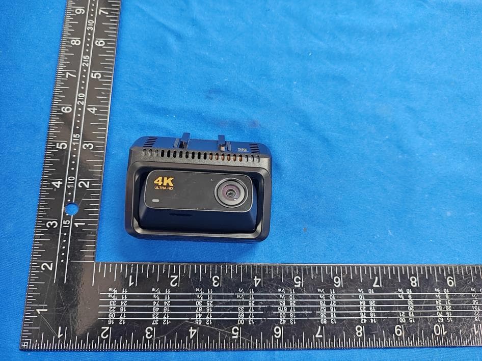
2AJFX-DZ2501A
Apr 17, 2026Dash Cam
Equipment Class
DTS - Digital Transmission System