2AJFX-MOLAE32.4G DDPai
DDPAI Technology Co., Ltd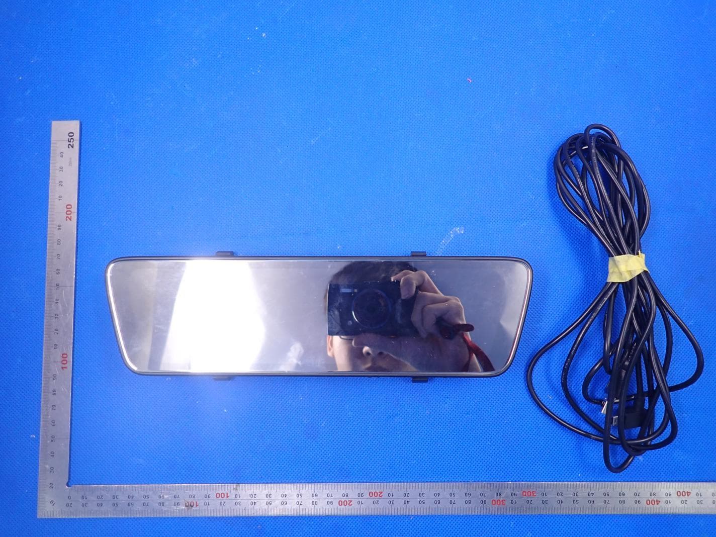
Click to zoom
Application Details
- Equipment Class
- DTS - Digital Transmission System
- Date of Grant
- Aug 11, 2020
- Application Purpose
- Original Equipment
- Date of Application
- Aug 11, 2020
- Equipment Note
- 2.4G DDPai
- Frequency Range
- 2412.00000000 - 2462.00000000
- Company
- DDPAI Technology Co., Ltd
- Country
- China
Documents & Files
Document Text
Text extracted from the exhibit documents filed with the FCC. Open a document above to read the original.
Users Manual
平面展开图· CJC)p,:::::司l 回PACKAGECONTENTS ii] CUSTOMER SUPP。RT 飞飞J、\、 变二J =;; Front Came阻 ♂b G京每载: 「 川 J 一 Poo.四rCable User Guide mole EJ 0 心县 //♂” ,,/二/ 飞_,,, 日川川叫曰21 川」才) 「1 J ,§气,2 元:飞Ji"'""』 酸喝」 Use「Guide 曰PRODUCTOVERVIEW e - 01 |行一。? 雪~.J---,,三七f 甲’J飞r~" 占-e 「 1二b 十干卢 目INSTALLATION 1.日indthef咱们tcamera。nthe o「i自inalrea『vie啊mirror with 1he buckle, and adlust the Angle cf由iefrom camera aπer II ls firmly lnstal 111ι (\ 回SCREENINTRODUTION After power-on, tap screen to display the menu. S田rltchtn album=SWlpe the screen to the rlgh1 to enter the album page, you can view the playback video, emergency files, e.nd sna口shotfiles. AdJust the prevle田••e•:Drag the traf)llzold Icon to move the current pr8'1iew area. Sett I 119 s: C lie K the Set四ngsle口nto enter !he camera Settings page. Album: Ciiek the icon to en1er the album pagero view the playback 111c:1eo, emer目eneyflles,and snapshotflles. Snapshot: Ciiek由esnapshot Icon to ca口turephotos. When capture with vloeo cllp Is turned on In the AJ;lp camera setti n自s,a video of 10/20/30 seconds duratiOn [set国ble】canbe generated. MIC: Click th11 MIC icon, open or CI0$8 the r&eording. Screen briglrtness: Slide up and down to adjust the screen b同目htness. Switch to the front p『eview:Swipe the sc『eenlo由e lefttoswltc问t。”、efronl preview. 曰INSTALLDDPAI APP For Android f IOS ph。nes,search !or 'DDPAI" I同the Google Play Sto『·白『AppleApp Store. Download the App and i同stallit on your phone. Note: In order t。connectro came咱WI-Fl,please list 1he A口pinyou『t『ustappli1;ati。nli5l and mak.s surs lhs caml!ra' sWl-Fllson. 曰APPINSTRUCTION 6.1臼、白eRoad D口PAIusers E。mmunlty,from here you cen find nearby users, see配enewest activities, user iixperlence, installation tutorial ete. ’曲曲,回』-- 寻~o亨t c..m ... I I ..\, on The目。&diA皿um• Soc恒lMedi a Sr arins 自.2Came胃a 臼用mu牛-Addcamera from nere. 帚忖。因车 P且IrSmart Phnn• to Dash Cam 1) Launch DD PAI App, ta,:i。内camera,then 111/.l M + , 2) Choose your DDPAI Dash Cam from lhe network llst (For Androlcl sys1em, App w111 start t•。searchD嗣hCam nolw口rkaulomatlcally. F口『IOSphone: turn on WLAN f『om'Settings•WI.AN’l . The Dash Cam' s defaull SSID (or WI-Fl name} Is DDPA.l_mola E3..J<XXX. 3) Ente『thepass we rd (the default passwo「di5 '123456 7890’] 4) Ciiek ADD CAMERA, wait a few seccmds unt ll the preview scre&n show. Preview/ Playback C<lnnect to Dash Cam via direct Wi-Fi, to see recunt videos a同dreal ti m@ di splay. l) Open the DDF'AI App, and add your Dasi、Cam. 2) Select Camera tab, then tap on(button. lh Is wlll brln"y'口Uto preview n且ge. 币:) 以附nload • Swllch b•twoon the front •ndre即preview Shutter buU~n ·刊Jrft!Ol8~<1SC也~emc~e Rotate your smB.rt phone口rpress expand ti icon, tum pr剧lewsc『eent。|町、dscapemode. Download Images and Videos Tap on t) from p『evlewscreen video E。d。•Wnl。ad. Down ln•d Image fl阳,= Downloa(l manually by: Tapl同g.;in d.;iwnloati Image向I~ from preview screen, thi! will bring you t白download page, you c;an select町归国slmplytap an tlie Images wn1c同youwant to II。wnl<1ad. The Image Illas can bo downloadetl automatically by: Going Into 'Me >Settings’,llJm on "Capture刊les 囚utodownload Download video files: 1 .Selectc:lownloao:lvlcle。flle$lro町1preview screen. 2.Drag ti me line bar to create the st自rtingp()int. 3.Tap on download Icon 9 ta start download. 4.Tap on finish icon。whenyou ha·咽madeyour selec田。n. 6.3S优ialM自diaSharing 。。 Taping on C Icon to share picture, vidao on social media like Fa.cebook, Twine『illC. 6.4Album h ... "“.. Er睛,m -=二 白奋。mλ Vlaw lma~H, videos and ama『gency巳lips,you also can edit四nd share th em from here. 6.5 Me Settings, help ~nter and about us. Settings: From here you can set Da5h Cam ’s name and password, cam町a•clumll, res。lutlon,G-Sensor sensitivity, pa『kingmcide, fgrmat $<I card, and S() on. Help: How to use the Dash Cam. About: U pllate firmwar也contact us, lnformatlcm a tJo ut I he Dash Cam. 目UPGRADEAPP AND FIRMWARE Update via App: If a new ver5lon of 1he fl rm ware 15 rel田S9d,open Ing t he App wlll prompt you to down lo Rd it. Yau can副soopen t he starin'1 app, ent11r "M11-> About t’,click to detect !he new version, the ap口Wiii auroma'lically download and u?grade. Ullgrade via SD card: Downie ad th8 latest f川11warefll『 your camera, UMI~ and copy tne conte网youliave unzipped onlo the SD国rd,t hen i nslall the SD card back camera. povier on the c国11eraand It wlll a口plythe flrmwaJe automatically NOTE:口。notPOW町。行y。”’口••1'Cam untll It begin• ocntlnuo阳 .. ~田ding田Hmay~a睛’阳rmanontd田阳囚,tothe Duh臼m. 回SPECIFICATIONS CPU: H.264hardware encoding,HiSilieon processor Tnuch Sc『sen:9.3S Inch LC口touchsc『een F『咽町tCame『aImage San•or. 4MP CMOS sensor Rear Camera Image Sensor: 2MP CMOS senso『 Frorrt Camera L111n$1 130" wide angle, F1 .4 四earCamara Lens: 125· wide angl乌F2.C Image Res。lution:f阳nt256口xi440. re21r1 920X1 OBO Video R粤,,t刷tlon:Front OUtl)Ut 2560X1440, F,。nt P『eview640•3 ao;同earOutput 1920X1 080,Rear Preview 640.360 Stnra11e: Class 1 0 TF card υp to 128 GB, loop recordln目 Wl·FI: Wi-Fi/ 2.4GHz Video Output: Wlreless vl4Jec output, s uppo11 Anc:trolc:t/ IOS device 。·Se自由。r:Buil•in S 13y『Gsensor, motion lock.i「111, adJustable sensitivity via App. or tcuch screen RAM:1GB 回FCC町'ATEME阳 This device complies wlt11 Part 15 of the FCC Rules. Opera四onIs subject lo the followlng two conditions, [ 1 J This device may not cause harmful in回斤@晴nc9. (2) This device mL1st accept any Interference rece旧时, including interfenmo that may cause undesi「ild 。口eratlon Warning: Changes or modlfk:atlons nol expressly app『oveelby the party responsible for compliance coulel 11old the u~r's euthorlty to口perate the eciulpment. NOTE: This equ旧marrthas bean 1ested and found 1c comply wllh tne llmlts lo「aClass B <Ilg Ital <IE"Ylce. pursuant to P且町15 ot the FCC Allies. These 1忖nitsa.re designed to provide『easgn ab le prow c苗。nagainst harmful In恒rlerenceIn a r哩,ld~ntlallnstallatlon. T his equipment gener副esuses and can rad late rad I口 f啤quancyan11『gyand, i『 notinstalled aiid used in ac~ordance wl臼theIns,阳ctlons,may cause harmful lnt erferance to ra\llo commun1cat1ono. H…
Text truncated - open the document above for the full version.
Cover Letter(s)
DDPAI Technology Co., Ltd. Agent Authorization Company: DDPAI Technology Co., Ltd. Address: Floor 12,Yihua finance building, Nanshan software industry park, Xuefu Rd, Nanshan district, Shenzhen, China Product Name: DDPai Model Number(s): mola E3 Product Description: 2.4G DDPai We authorize MiCOM Labs Inc., 575 Boulder Court, Pleasanton, California 94566, USA, to act on our behalf on all matters concerning the certification of above named equipment. We declare that MiCOM Labs Inc. is allowed to forward all information related to the approval and certification of equipment to the regulatory agencies as required and to discuss any issues concerning the approval application. Any and all acts carried out by MiCOM Labs on our behalf shall have the same effect as acts of our own. Signature: Date: 2020-08-10 Name: Victor Song’ Company: DDPAI Technology Co., Ltd.
External Photos
External Photos ALL VIEW OF EUT TOP VIEW OF EUT BOTTOM VIEW OF EUT FRONT VIEW OF EUT BACK VIEW OF EUT LEFT VIEW OF EUT RIGHT VIEW OF EUT VIEW OF EUT(PORT)
ID Label/Location Info
FCC ID Label Location 50mm& 20mm FCC ID: 2AJFX-MOLAE3
Internal Photos
Internal Photos OPEN VIEW OF EUT OPEN VIEW OF EUT-2 WIFI Antenna INTERNAL VIEW-1 OF EUT INTERNAL VIEW-2 OF EUT INTERNAL VIEW-3 OF EUT INTERNAL VIEW-4 OF EUT INTERNAL VIEW-5 OF EUT INTERNAL VIEW-6 OF EUT INTERNAL VIEW-7 OF EUT VIEW OF BATTERY
RF Exposure Info
RF EXPOSURE EVALUATION 1. PRODUCT INFORMATION Product Description DDPai Model Name mola E3 FCC ID 2AJFX-MOLAE3 2. EVALUATION METHOD AND LIMIT Human exposure to RF emissions from mobile devices (47 CFR §2.1091) may be evaluated based on the MPE limits adopted by the FCC for electric and magnetic field strength and/or power density, as appropriate, since exposures are assumed to occur at distances of 20 cm or more from persons. LIMITS FOR GENERAL POPULATION / UNCONTROLLED EXPOSURE Frequency Range (MHz) E-field Strength (E) (V/m) Magnetic Field Strength (H) (A/m) Power Density (S) (mW/cm 2 ) Averaging Time |E| 2 , |H| 2 or S (Minutes) 0.3 -- 1.34 614 1.63 (100)* 30 1.34 -- 30 824/f 2.19/f (180/f 2 )* 30 30 -- 300 27.5 0.073 0.2 30 300 -- 1500 -- -- f/1500 30 1500 -- 100,000 -- -- 1.0 30 *Note: 1. f= Frequency in MHz * Plane-wave Equivalent Power Density 2. The averaging time for General Population/Uncontrolled exposure to fixed transmitters is not applicable for mobile and portable transmitters. See 47 CFR §§2.1091 and 2.1093 on source-based time-averaging requirement for mobile and portable transmitters. S=PG/4πR² Where: S=power density P=power input to antenna G=power gain of the antenna in the direction of interest relative to an isotropic radiator R=distance to the center of radiation of the antenna CALCULATION A minimum test separation distance ≥ 20 cm is required between the antenna and radiating structures of the device and nearby persons to apply mobile device exposure limits. The distance must be at least 20 cm and fully supported by the operating and installation configurations of the transmitter and its antenna(s), according to the source-based time-averaged maximum power requirements of § 2.1091(d)(2). In cases where cable losses or other attenuations are applied to determine compliance, the most conservative operating configurations and exposure conditions must be evaluated. 2.4G WIFI Antenna Gain=2.05dBi (Numeric 1.60), π=3.14 Note: 1. Only the worst case recorded. 3. Conclusion Compliance the RF exposure requirement Frequency Output Power Output Power Power Density Power Density Limit MHz dBm mW mW/cm 2 mW/cm 2 2462 12.66 18.45 0.0059 1
Test Report
Page 1 of 86 Report No.: AGC05414200701FE05 FCC ID : 2AJFX-MOLAE3 APPLICATION PURPOSE : Original Equipment PRODUCT DESIGNATION : DDPai BRAND NAME : ddpai MODEL NAME : mola E3 APPLICANT : DDPAI Technology Co., Ltd. DATE OF ISSUE : Jul. 21, 2020 STANDARD(S) TEST PROCEDURE(S) : FCC Part 15.247 REPORT VERSION : V1.0 Attestation of Global Compliance (Shenzhen) Co., Ltd CAUTION: This report shall not be reproduced except in full without the written permission of the test laboratory and shall not be quoted out of context. FCC Test Report Report No.: AGC05414200701FE05 Page 2 of 86 REPORT REVISE RECORD Report Version Revise Time Issued Date Valid Version Notes V1.0 / Jul. 21, 2020 Valid Initial Release Report No.: AGC05414200701FE05 Page 3 of 86 TABLE OF CONTENTS 1. VERIFICATION OF CONFORMITY ............................................................................................................... 5 2. GENERAL INFORMATION ............................................................................................................................ 6 2.1. PRODUCT DESCRIPTION ..................................................................................................................... 6 2.2. TABLE OF CARRIER FREQUENCYS ..................................................................................................... 6 2.3. IEEE 802.11N MODULATION SCHEME .................................................................................................. 7 2.4. RELATED SUBMITTAL(S) / GRANT (S) .................................................................................................. 7 2.5. TEST METHODOLOGY .......................................................................................................................... 7 2.6. SPECIAL ACCESSORIES ....................................................................................................................... 7 2.7. EQUIPMENT MODIFICATIONS .............................................................................................................. 7 2.8. ANTENNA REQUIREMENT .................................................................................................................... 8 3. MEASUREMENT UNCERTAINTY ................................................................................................................. 9 4. DESCRIPTION OF TEST MODES ............................................................................................................... 10 5. SYSTEM TEST CONFIGURATION ............................................................................................................. 11 5.1. CONFIGURATION OF EUT SYSTEM .................................................................................................... 11 5.2. EQUIPMENT USED IN EUT SYSTEM .................................................................................................... 11 5.3. SUMMARY OF TEST RESULTS ............................................................................................................. 11 6. TEST FACILITY ........................................................................................................................................... 12 7. OUTPUT POWER ........................................................................................................................................ 13 7.1. MEASUREMENT PROCEDURE ........................................................................................................... 13 7.2. TEST SET-UP (BLOCK DIAGRAM OF CONFIGURATION) ................................................................... 13 7.3. LIMITS AND MEASUREMENT RESULT ............................................................................................... 14 8. 6 DB BANDWIDTH ...................................................................................................................................... 16 8.1. MEASUREMENT PROCEDURE ........................................................................................................... 16 8.2. TEST SET-UP (BLOCK DIAGRAM OF CONFIGURATION) ................................................................... 16 8.3. LIMITS AND MEASUREMENT RESULTS ............................................................................................. 17 9. CONDUCTED SPURIOUS EMISSION ........................................................................................................ 25 Report No.: AGC05414200701FE05 Page 4 of 86 9.1. MEASUREMENT PROCEDURE ........................................................................................................... 25 9.2. TEST SET-UP (BLOCK DIAGRAM OF CONFIGURATION) ................................................................... 25 9.3. MEASUREMENT EQUIPMENT USEDJN ............................................................................................. 25 9.4. LIMITS AND MEASUREMENT RESULT ............................................................................................... 25 10. MAXIMUM CONDUCTED OUTPUT POWER SPECTRAL DENSITY ....................................................... 44 10.1 MEASUREMENT PROCEDURE .......................................................................................................... 44 10.2 TEST SET-UP (BLOCK DIAGRAM OF CONFIGURATION) .................................................................. 44 10.3 MEASUREMENT EQUIPMENT USED ................................................................................................. 44 10.4 LIMITS AND MEASUREMENT RESULT .............................................................................................. 44 11. RADIATED EMISSION ............................................................................................................................... 52 11.1. MEASUREMENT PROCEDURE ......................................................................................................... 52 11.2. TEST SETUP ...................................................…
Text truncated - open the document above for the full version.
Test Report
Report No.: AGC05414200701FE05 Page 47 of 86 TEST PLOT OF SPECTRAL DENSITY FOR HIGH CHANNEL 802.11g TEST RESULT TEST PLOT OF SPECTRAL DENSITY FOR LOW CHANNEL Report No.: AGC05414200701FE05 Page 48 of 86 TEST PLOT OF SPECTRAL DENSITY FOR MIDDLE CHANNEL TEST PLOT OF SPECTRAL DENSITY FOR HIGH CHANNEL Report No.: AGC05414200701FE05 Page 49 of 86 802.11n 20 TEST RESULT TEST PLOT OF SPECTRAL DENSITY FOR LOW CHANNEL TEST PLOT OF SPECTRAL DENSITY FOR MIDDLE CHANNEL Report No.: AGC05414200701FE05 Page 50 of 86 TEST PLOT OF SPECTRAL DENSITY FOR HIGH CHANNEL 802.11n 40 TEST RESULT TEST PLOT OF SPECTRAL DENSITY FOR LOW CHANNEL Report No.: AGC05414200701FE05 Page 51 of 86 TEST PLOT OF SPECTRAL DENSITY FOR MIDDLE CHANNEL TEST PLOT OF SPECTRAL DENSITY FOR HIGH CHANNEL Report No.: AGC05414200701FE05 Page 52 of 86 11. RADIATED EMISSION 11.1. MEASUREMENT PROCEDURE 1. The EUT was placed on the top of the turntable 0.8 or 1.5 meter above ground. The phase center of the receiving antenna mounted on the top of a height-variable antenna tower was placed 3 meters far away from the turntable. 2. Power on the EUT and all the supporting units. The turntable was rotated by 360 degrees to determine the position of the highest radiation. 3. The height of the broadband receiving antenna was varied between one meter and four meters above ground to find the maximum emissions field strength of both horizontal and vertical polarization. 4. For each suspected emissions, the antenna tower was scan (from 1 M to 4 M) and then the turntable was rotated (from 0 degree to 360 degrees) to find the maximum reading. 5. Set the test-receiver system to Peak or CISPR quasi-peak Detect Function with specified bandwidth under Maximum Hold Mode. 6. For emissions above 1GHz, use 1MHz RBW and 3MHz VBW for peak reading. Place the measurement antenna away from each area of the EUT determined to be a source of emissions at the specified measurement distance, while keeping the measurement antenna aimed at the source of emissions at each frequency of significant emissions, with polarization oriented for maximum response. The measurement antenna may have to be higher or lower than the EUT, depending on the radiation pattern of the emission and staying aimed at the emission source for receiving the maximum signal. The final measurement antenna elevation shall be that which maximizes the emissions. The measurement antenna elevation for maximum emissions shall be restricted to a range of heights of from 1 m to 4 m above the ground or reference ground plane. 7. When the radiated emissions limits are expressed in terms of the average value of the emissions, and pulsed operation is employed, the measurement field strength shall be determined by averaging over one complete pulse train, including blanking intervals, as long as the pulse train does not exceed 0.1 seconds. As an alternative (provided the transmitter operates for longer than 0.1 seconds) or in cases where the pulse train exceeds 0.1 seconds, the measured field strength shall be determined from the average absolute voltage during a 0.1 second interval during which the field strength is at its maximum values. 8.If the emissions level of the EUT in peak mode was 3 dB lower than the average limit specified, then testing will be stopped and peak values of EUT will be reported, otherwise, the emissions which do not have 3 dB margin will be repeated one by one using the quasi-peak method for below 1GHz. 9. For testing above 1GHz, the emissions level of the EUT in peak mode was lower than average limit (that means the emissions level in peak mode also complies with the limit in average mode), then testing will be stopped and peak values of EUT will be reported, otherwise, the emissions will be measured in average mode again and reported. 10. In case the emission is lower than 30MHz, loop antenna has to be used for measurement and the recorded data should be QP measured by receiver. High - Low scan is not required in this case. Report No.: AGC05414200701FE05 Page 53 of 86 11.2. TEST SETUP Radiated Emission Test-Setup Frequency Below 30MHz RADIATED EMISSION TEST SETUP 30MHz-1000MHz RADIATED EMISSION TEST SETUP ABOVE 1000MHz Report No.: AGC05414200701FE05 Page 54 of 86 11.3. LIMITS AND MEASUREMENT RESULT 15.209(a) Limit in the below table has to be followed Frequencies (MHz) Field Strength (micorvolts/meter) Measurement Distance (meters) 0.009~0.490 2400/F(KHz) 300 0.490~1.705 24000/F(KHz) 30 1.705~30.0 30 30 30~88 100 3 88~216 150 3 216~960 200 3 Above 960 500 3 Note: All modes were tested For restricted band radiated emission, the test records reported below are the worst result compared to other modes. 11.4. TEST RESULT RADIATED EMISSION BELOW 30MHZ Emissions are attenuated more than 20 dB below the permissible value Report No.: AGC05414200701FE05 Page 55 of 86 RADIATED EMISSION BELOW 1GHZ EUT DDPai Model Name mola E3 Temperature 25°C Relative Humidity 55.4% Pressure 960hPa Test Voltage Normal Voltage Test Mode 802.11b with date rate 1 2412MHZ Antenna Horizontal RESULT: PASS Report No.: AGC05414200701FE05 Page 56 of 86 EUT DDPai Model Name mola E3 Temperature 25°C Relative Humidity 55.4% Pressure 960hPa Test Voltage Normal Voltage Test Mode 802.11b with date rate 1 2412MHZ Antenna Vertical RESULT: PASS Note: 1. Factor=Antenna Factor + Cable loss, Margin=Measurement-Limit. 2. The “Factor” value can be calculated automatically by software of measurement system. 3. All test modes had been pre-tested. The 802.11b at low channel is the worst case and recorded in the report. Report No.: AGC05414200701FE05 Page 57 of 86 RADIATED EMISSION ABOVE 1GHZ EUT DDPai Model Name mola E3 Temperature 25°C Relative Humidity 55.4% Pressure 960hPa Test Voltage Normal Voltage Test Mode 802.11b with date rate 1 2412MHZ Antenna Horizontal FrequencyMeter ReadingFactor Emission LevelLimitsMargin (MHz)(dBμV) (dB)(dBμV/m)(dBμV/m)(dB) Value Type 4824.000 56.0274-17.98 peak 4824.000 47.2154-6.79 AVG 7236.000 54.3874-19.62 peak …
Text truncated - open the document above for the full version.
Test Report
Report No.: AGC05414200701FE05 Page 79 of 86 BOTTOM VIEW OF EUT FRONT VIEW OF EUT Report No.: AGC05414200701FE05 Page 80 of 86 BACK VIEW OF EUT LEFT VIEW OF EUT Report No.: AGC05414200701FE05 Page 81 of 86 RIGHT VIEW OF EUT VIEW OF EUT(PORT) Report No.: AGC05414200701FE05 Page 82 of 86 OPEN VIEW OF EUT OPEN VIEW OF EUT-2 WIFI Antenna Report No.: AGC05414200701FE05 Page 83 of 86 INTERNAL VIEW-1 OF EUT INTERNAL VIEW-2 OF EUT Report No.: AGC05414200701FE05 Page 84 of 86 INTERNAL VIEW-3 OF EUT INTERNAL VIEW-4 OF EUT Report No.: AGC05414200701FE05 Page 85 of 86 INTERNAL VIEW-5 OF EUT INTERNAL VIEW-6 OF EUT Report No.: AGC05414200701FE05 Page 86 of 86 INTERNAL VIEW-7 OF EUT VIEW OF BATTERY ----END OF REPORT---- Conditions of Issuance of Test Reports 1. All samples and goods are accepted by the Attestation of Global Compliance (Shenzhen) Co., Ltd (the “Company”) solely for testing and reporting in accordance with the following terms and conditions. The company provides its services on the basis that such terms and conditions constitute express agreement between the company and any person, firm or company requesting its services (the “Clients”). 2. Any report issued by Company as a result of this application for testing services (the “Report”) shall be issued in confidence to the Clients and the Report will be strictly treated as such by the Company. It may not be reproduced either in its entirety or in part and it may not be used for advertising or other unauthorized purposes without the written consent of the Company. The Clients to whom the Report is issued may, however, show or send it, or a certified copy thereof prepared by the Company to its customer, supplier or other persons directly concerned. The Company will not, without the consent of the Clients, enter into any discussion or correspondence with any third party concerning the contents of the Report, unless required by the relevant governmental authorities, laws or court orders. 3.The Company shall not be called or be liable to be called to give evidence or testimony on the Report in a court of law without its prior written consent, unless required by the relevant governmental authorities, laws or court orders. 4. The non-CMA report issued by AGC is only permitted to be used by the client as internal reference use and shall not be used for public demonstration purpose. 5. In the event of the improper use of the report as determined by the Company, the Company reserves the right to withdraw it, and to adopt any other additional remedies which may be appropriate. 6. Samples submitted for testing are accepted on the understanding that the Report issued cannot form the basis of, or be the instrument for, any legal action against the Company. 7. The Company will not be liable for or accept responsibility for any loss or damage however arising from the use of information contained in any of its Reports or in any communication whatsoever about its said tests or investigations. 8.Clients wishing to use the Report in court proceedings or arbitration shall inform the Company to that effect prior to submitting the sample for testing. 9. The Company is not responsible for recalling the electronic version of the original report when any revision is made to them. The Client assumes the responsibility to providing the revised version to any interested party who uses them. 10. Subject to the variable length of retention time for test data and report stored hereinto as otherwise specifically required by individual accreditation authorities, the Company will only keep the supporting test data and information of the test report for a period of six years. The data and information will be disposed of after the aforementioned retention period has elapsed. Under no circumstances shall we provide any data and information which has been disposed of after retention period. Under no circumstances shall we be liable for damage of any kind, including (but not limited to) compensatory damages, lost profits, lost data, or any form of special, incidental, indirect, consequential or punitive damages of any kind, whether based on breach of contract of warranty, tort (including negligence), product liability or otherwise, even if we are informed in advance of the possibility of such damages.
Test Setup Photos
Test Setup Photos FCC RADIATED EMISSION TEST SETUP BELOW 1GHZ FCC RADIATED EMISSION TEST SETUP ABOVE 1GHZ
Contact Information
Applicant
Sean Yu(Certification Engineer)
Technical Contact
Test Firm
Attestation of Global Compliance (Shenzhen) Co., LDoris Li
[email protected]+86-755-25234088
Technical Specifications
| # | Rule Parts | Frequency Range | Power Output |
|---|---|---|---|
| 1 | 15C | 2.41 GHz - 2.46 GHz | 18.50 mW |
Other Applications from DDPAI Technology Co., Ltd
2AJFX-DE001
Aug 28, 2026Dash Cam
Equipment Class
DTS - Digital Transmission System
2AJFX-DM2505A
Aug 27, 2026Dash Cam
Equipment Class
NII - Unlicensed National Information Infrastructure TX2AJFX-DN2602
Aug 19, 2026Dash Cam
Equipment Class
DTS - Digital Transmission System
2AJFX-DZ2502
Jul 28, 2026Dash Cam
Equipment Class
DTS - Digital Transmission System
2AJFX-DZ2501A
Apr 17, 2026Dash Cam
Equipment Class
DTS - Digital Transmission System