2AJFX-Z40Dashcam
DDPAI Technology Co., Ltd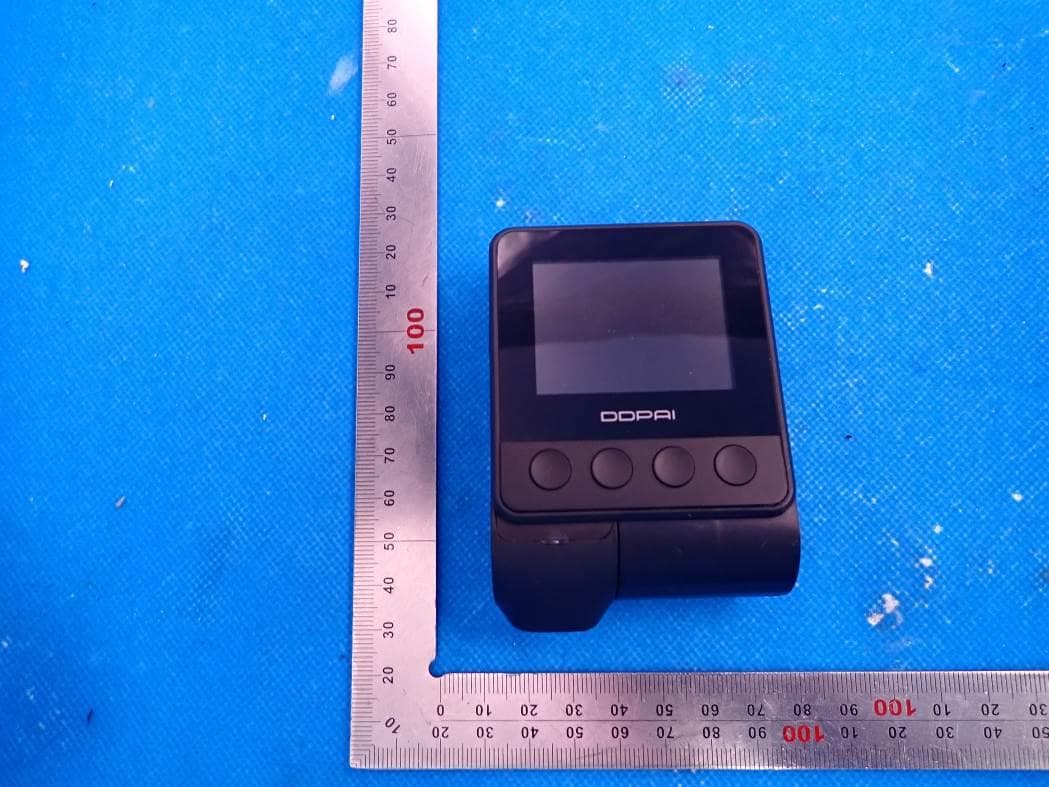
Click to zoom
Application Details
- Equipment Class
- DTS - Digital Transmission System
- Date of Grant
- Aug 02, 2021
- Application Purpose
- Original Equipment
- Date of Application
- Aug 02, 2021
- Equipment Note
- Dashcam
- Frequency Range
- 2412.00000000 - 2462.00000000
- Company
- DDPAI Technology Co., Ltd
- Country
- China
Documents & Files
Document Text
Text extracted from the exhibit documents filed with the FCC. Open a document above to read the original.
Users Manual
客户品牌:DDPAI项目名称: Z40(海外版)折叠样式:骑马钉产品料号:20204000216版本类型:V0.1归档日期:20210429 设计人员:曾丽苗 复查人员:罗琴 产品经理:陈昶珲 项目经理:徐华勤 包装类型:说明书 比例尺寸:1 :1 材质:105g双铜纸 尺寸:70*120mm 工艺:油墨印刷 颜色:彩色 User Guide Nazwa produktu:Rejestrator samochodowy Model:Z40 Rozmiar:81x61x33mm Wejście:5V 2A Pamięć:Karta TF (do 128 GB), nagrywanie zapętlone Wi-Fi: Wi-Fi/2.4GHz G-czujnik:Wbudowany 3-żyro czujnik, blokada ruchu, regulowana czułość za pomocą aplikacji RAM: 2Gb 2 ZAWARTOŚĆ OPAKOW ANI A1 SPECYFIKACJ A · · · · · · · · Etykieta statyczna Uchwyt Narzędzie instalacyjne Instrukcja obsługi Rejestrator samochodowy Ładowarka USB Taśma klejąca 3M Przewód zasilający 3 PRODUCT O VERVIEW 1 Dash Cam Screen 5 MIC 2 Working Indicator 6 TF Card Slot 3 AV Interface 4Type-C Power Interface 7 Lens Button Description Function description 1 Set 2 Sound Recording 3 Album Click the button to enter the settings selection. Click the button to turn on/off recording. Click the button to open the album. Click the button to turn on/off the screen. Reset: Long press 6s to reset. 4 Lock 3 4 7 5 6 1 2 123 4 1 экран 5 МИК 2 Индикатор работы 6 Гнездо для карты Micro SD 3 AV интерфейс 4Интерфейс питания типа C 7 Объектив Описание кнопки Описание функции Нажмите кнопку для выбора параметров. Нажмите кнопку для включения / выключения записи. Нажмите кнопку для открытия альбома. Нажмите кнопку для включения / выключения экрана. Перезагрузка: Удерживайте в течение 6 сек. для перезагрузки. 1 Настройки 2 Звукозапись 3 альбом 4 выключатель 3 4 7 5 6 1 2 123 4 6 APP INSTRUCTION Scan the QR code to download the "DDPAI" App. Install DDPAI App Pair S mart Phone to D ash C am 1.Keep the Dash Cam and mobile phone within 2.5meters. 2.Launch DDPAI App, tap on “Device > Connect new devices”. 3.Choose your DDPAI Dash Cam from the network list(For Android system, App will start to search Dash Cam network automatically. For iOS phone: t urn on WLAN from “Settings ->WLAN”). The Dash Cam’s default SSID (or Wi-Fi name) is DDPAI_Z40_XXXX. 4.Enter the password (the default password is ‘1234 567890’). 5.Enter DDPAI App, wait a few seconds until the preview screen show. iOSAndroid Preview 1.Open the DDPAI App, and add your Dash Cam. 2.Select “Device > Entering” tab, this will bring you to the preview page. Rotate your smart phone or press expand icon, turn the preview screen to landscape mode. < + Now&back Capture Emergency . < + Now&back Capture Emergency . On The RoadDeviceMe Entering ... + < + Now&back Capture Emergency . Timeline bar < + Now&back Capture Emergency . thumbnail Tap and left/right drag timeline bar at the screen bottom to create the starting point of the recording you wish to preview, then tap on thumbnail when you have made your selection, or wait for 5 sec for buffering, now you can watch the history recording. Playback 1.Tap and left/right drag timeline bar at the screen bottom to create the starting point of the recording you wish to download, then tap on thumbnail when you have made your selection, or wait for 5 sec for buffering, to enter the download start screen. 2.Tap on from preview screen to enter the download interface. 3.After the video has finished downloading, click "Complete". Download Video Files For more information and FAQs, Please scan the QR code: www.ddpai.com [email protected] DDPAI Technology Co., Ltd Floor 12, Yihua finance building, Software Park, Y uehai Sub district, Nanshan district, Shenzhen CONTACT 6 ИНСТРУКЦИЯ ДЛЯ ПРИЛО ЖЕНИЯ Отсканируйте QR-код, чтобы загрузить прило жение «DDPAI». Установить приложение DDPAI Сопряжение с мартфона с в идеор егистратором Предв ари тельный просмотр iOSAndroid 1.Держите диктофо н и мобильный телефон в пределах 2,5 метров. 1.Откройте прило жение DDPAI и добавь те ваш видеорегистратор. 2.Выбер ите «оборудование> входящий», это приведет вас н а страниц у предвари тельного просм отра. 2.Запустит е прило жение DDPAI, нажмите на” оборудован ие > Подключить нов ое устройс тво”. 3.Выбер ите ваш видеорегистратор DDPAI из списка сетей (Для системы Android прило жение начнет поис к сети видеорегистратора автомат ически. Д ля системы iOS включите WLAN в меню «Настройки ->WLAN»). И дентифи катор SSID видеорегистратора по у молчанию ( или наименован ие в сети Wi-Fi) DDPAI_Z40_XXXX. 4.Введите пароль (пароль по у молчанию: 1234567890). 5.Войд ите в прило жение DDPAI и подождите несколько с екунд, пок а не отобразит ся экран предвари тельног о п росм отра. воспроизведение Скачать видео ф айлыПоверните смартфон или нажмите на значок разворачиван ия . Переключите экран предвари тельного п росм отра в л андшаф тный режим. Нажмите и перет ащит е влево/вправо в ременную шкалу вни зу экрана, чтобы создать н ачальную т очку записи, кото рую необходимо п росм отрет ь. З атем, когда выбор сделан, нажмите на пик тограмму или подождите 5 сек. д ля буферизац ии. Т еперь можно просм отрет ь запись. 1.Нажмите и перет ащит е влево / в право ш калу шкалы времени в н ижней части экрана, что бы создать начальную точку зап иси, кото рую вы хотит е загрузить , затем нажмите миниатюру, когда сделаете свой выбор, или подождите 5 сек унд для буферизации, чтобы начать загрузку экран. 3.По о кончании загрузки видео н ажмите «выполнено». 2.Нажмите на н а экране предвари тельного просм отра, чтобы войти в интерфе йс з агрузки. Дляпо лучениядополнит ельнойинформа цииио тветовначастозадаваемыевопро сыотсканир уйт еQR-к од: www.ddpai.com [email protected] DDPAI Technology Co., Ltd Шэнь чжэнь, район Наньшань, по драйон Юэхай, Софтвэа парк, здание Ихуа Файненс, этаж 12 КОНТАКТЫ 6 INSTRUKCJA OBSŁUGI APLIKACJI Zeskanuj kod QR, aby pobrać aplikację „DDPAI”. Zainstaluj aplikację DDPAI Parowanie smartfonu z kamerą Podgląd iOSAndroid 1.Trzymaj rejestrator jazdy i telefon komórkowy w promieniu 2,5 metra. 1.Otworzyć aplikację DDPAI i dodać kamerę samochodową. 2.Wybierz „Urządzenie> wchodzić”,spowoduje to przejście do strony podglądu. Po obróceniu smartfonu lub naciś nięciu przycisku trybu pełnoekranowego na ekranie pojawi się widok w orientacji poziomej. 4.Wprowa…
Text truncated - open the document above for the full version.
Cover Letter(s)
DDPAI Technology Co., Ltd Agent Authorization Company: DDPAI Technology Co., Ltd Address: Floor 12, Yihua finance building, Nanshan software industry park, Xuefu Rd, Nanshan district, Shenzhen, China Product Name: Dashcam Model Number(s): Z40 Product Description: Dashcam We authorize MiCOM Labs Inc., 575 Boulder Court, Pleasanton, California 94566, USA, to act on our behalf on all matters concerning the certification of above named equipment. We declare that MiCOM Labs Inc. is allowed to forward all information related to the approval and certification of equipment to the regulatory agencies as required and to discuss any issues concerning the approval application. Any and all acts carried out by MiCOM Labs on our behalf shall have the same effect as acts of our own. Signature: Date: 2021-07-29 Name: Victor Song Company: DDPAI Technology Co., Ltd
External Photos
External Photos ALL VIEW OF EUT TOP VIEW OF EUT BOTTOM VIEW OF EUT FRONT VIEW OF EUT BACK VIEW OF EUT LEFT VIEW OF EUT RIGHT VIEW OF EUT PORT VIEW OF EUT-1 PORT VIEW OF EUT-2
Internal Photos
Internal Photos OPEN VIEW OF EUT INTERNAL VIEW-1 OF EUT INTERNAL VIEW-2 OF EUT INTERNAL VIEW-3 OF EUT INTERNAL VIEW-4 OF EUT INTERNAL VIEW-5 OF EUT INTERNAL VIEW-6 OF EUT INTERNAL VIEW-7 OF EUT INTERNAL VIEW-8 OF EUT INTERNAL VIEW-9 OF EUT INTERNAL VIEW-10 OF EUT INTERNAL VIEW-11 OF EUT INTERNAL VIEW-12 OF EUT INTERNAL VIEW-13 OF EUT WIFI Antenna INTERNAL VIEW-14 OF EUT INTERNAL VIEW-15 OF EUT GPS Receiver Antenna INTERNAL VIEW-16 OF EUT INTERNAL VIEW-17 OF EUT
RF Exposure Info
RF EXPOSURE EVALUATION 1. PRODUCT INFORMATION Product Description Dashcam Model Name DDPAI FCC ID 2AJFX-Z40 2. EVALUATION METHOD AND LIMIT Human exposure to RF emissions from mobile devices (47 CFR §2.1091) may be evaluated based on the MPE limits adopted by the FCC for electric and magnetic field strength and/or power density, as appropriate, since exposures are assumed to occur at distances of 20 cm or more from persons. LIMITS FOR GENERAL POPULATION / UNCONTROLLED EXPOSURE Frequency Range (MHz) E-field Strength (E) (V/m) Magnetic Field Strength (H) (A/m) Power Density (S) (mW/cm 2 ) Averaging Time |E| 2 , |H| 2 or S (Minutes) 0.3 -- 1.34 614 1.63 (100)* 30 1.34 -- 30 824/f 2.19/f (180/f 2 )* 30 30 -- 300 27.5 0.073 0.2 30 300 -- 1500 -- -- f/1500 30 1500 -- 100,000 -- -- 1.0 30 *Note: 1. f= Frequency in MHz * Plane-wave Equivalent Power Density 2. The averaging time for General Population/Uncontrolled exposure to fixed transmitters is not applicable for mobile and portable transmitters. See 47 CFR §§2.1091 and 2.1093 on source-based time-averaging requirement for mobile and portable transmitters. S=PG/4πR² Where: S=power density P=power input to antenna G=power gain of the antenna in the direction of interest relative to an isotropic radiator R=distance to the center of radiation of the antenna CALCULATION A minimum test separation distance ≥ 20 cm is required between the antenna and radiating structures of the device and nearby persons to apply mobile device exposure limits. The distance must be at least 20 cm and fully supported by the operating and installation configurations of the transmitter and its antenna(s), according to the source-based time-averaged maximum power requirements of § 2.1091(d)(2). In cases where cable losses or other attenuations are applied to determine compliance, the most conservative operating configurations and exposure conditions must be evaluated. Antenna Gain=2dBi (Numeric 1.58), π=3.14 Note: 1. Only the worst case recorded. Frequency Output Power Output Power Power Density Power Density Limit MHz dBm mW mW/cm 2 mW/cm 2 2462 14.57 28.64 0.009 1
Test Report
Page 1 of 94 Report No.: AGC05414210503FE05 FCC ID : 2AJFX-Z40 APPLICATION PURPOSE : Original Equipment PRODUCT DESIGNATION : Dashcam BRAND NAME : DDPAI MODEL NAME : Z40 APPLICANT : DDPAI Technology Co., Ltd DATE OF ISSUE : Jul. 22, 2021 STANDARD(S) TEST PROCEDURE(S) : FCC Part 15.247 REPORT VERSION : V1.0 Attestation of Global Compliance (Shenzhen) Co., Ltd FCC Test Report Report No.: AGC05414210503FE05 Page 2 of 94 REPORT REVISE RECORD Report Version Revise Time Issued Date Valid Version Notes V1.0 / Jul. 22, 2021 Valid Initial Release Report No.: AGC05414210503FE05 Page 3 of 94 TABLE OF CONTENTS 1. VERIFICATION OF CONFORMITY .................................................................................................................. 5 2. GENERAL INFORMATION .............................................................................................................................. 6 2.1. PRODUCT DESCRIPTION ........................................................................................................................ 6 2.2. TABLE OF CARRIER FREQUENCYS ....................................................................................................... 6 2.3. IEEE 802.11N MODULATION SCHEME .................................................................................................... 7 2.4. RELATED SUBMITTAL(S) / GRANT (S) .................................................................................................... 7 2.5. TEST METHODOLOGY ............................................................................................................................. 7 2.6. SPECIAL ACCESSORIES ......................................................................................................................... 7 2.7. EQUIPMENT MODIFICATIONS ................................................................................................................. 7 2.8. ANTENNA REQUIREMENT....................................................................................................................... 8 3. MEASUREMENT UNCERTAINTY ................................................................................................................... 9 4. DESCRIPTION OF TEST MODES ................................................................................................................. 10 5. SYSTEM TEST CONFIGURATION ................................................................................................................ 11 5.1. CONFIGURATION OF EUT SYSTEM ...................................................................................................... 11 5.2. EQUIPMENT USED IN EUT SYSTEM ..................................................................................................... 11 5.3. SUMMARY OF TEST RESULTS .............................................................................................................. 11 6. TEST FACILITY .............................................................................................................................................. 12 7. OUTPUT POWER ........................................................................................................................................... 13 7.1. MEASUREMENT PROCEDURE ............................................................................................................. 13 7.2. TEST SET-UP (BLOCK DIAGRAM OF CONFIGURATION) .................................................................... 13 7.3. LIMITS AND MEASUREMENT RESULT .................................................................................................. 14 8. BANDWIDTH .................................................................................................................................................. 15 8.1. MEASUREMENT PROCEDURE ............................................................................................................. 15 8.2. TEST SET-UP (BLOCK DIAGRAM OF CONFIGURATION) .................................................................... 15 8.3. LIMITS AND MEASUREMENT RESULTS ............................................................................................... 16 9. CONDUCTED SPURIOUS EMISSION........................................................................................................... 29 9.1. MEASUREMENT PROCEDURE ............................................................................................................. 29 9.2. TEST SET-UP (BLOCK DIAGRAM OF CONFIGURATION) .................................................................... 29 9.3. MEASUREMENT EQUIPMENT USEDJN ................................................................................................ 29 9.4. LIMITS AND MEASUREMENT RESULT .................................................................................................. 29 Report No.: AGC05414210503FE05 Page 4 of 94 10. MAXIMUM CONDUCTED OUTPUT POWER SPECTRAL DENSITY ........................................................ 44 10.1 MEASUREMENT PROCEDURE ............................................................................................................ 44 10.2 TEST SET-UP (BLOCK DIAGRAM OF CONFIGURATION) ................................................................... 44 10.3 MEASUREMENT EQUIPMENT USED ................................................................................................... 44 10.4 LIMITS AND MEASUREMENT RESULT ................................................................................................. 44 11. RADIATED EMISSION ................................................................................................................................. 51 11.1. MEASUREMENT PROCEDURE............................................................................................................ 51 11.2. TEST SETUP ................................................................................................................................…
Text truncated - open the document above for the full version.
Test Report
Report No.: AGC05414210503FE05 Page 43 of 94 Test_Graph_802.11n20_ANT1_2412_MCS0_Lower Band Edge Emissions Test_Graph_802.11n40_ANT1_2422_MCS0_Lower Band Edge Emissions Note: Emissions from 2483.5-2500MHz which fall in the restricted bands had been considered with the radiated emission limits specified. Report No.: AGC05414210503FE05 Page 44 of 94 10. MAXIMUM CONDUCTED OUTPUT POWER SPECTRAL DENSITY 10.1 MEASUREMENT PROCEDURE (1). Connect EUT RF output port to the Spectrum Analyzer through an RF attenuator (2). Set the EUT Work on the top, the middle and the bottom operation frequency individually. (3). Set SPA Trace 1 Max hold, then View. Note: The method of PKPSD in the ANSI C63.10 (2013) item 11.10 was used in this testing. 10.2 TEST SET-UP (BLOCK DIAGRAM OF CONFIGURATION) Refer to Section 8.2. 10.3 MEASUREMENT EQUIPMENT USED Refer to Section 6. 10.4 LIMITS AND MEASUREMENT RESULT Test Data of Conducted Output Power Spectral Density Test Mode Test Channel (MHz) Power density (dBm/20kHz) Power density (dBm/3kHz) Limit (dBm/3kHz) Pass or Fail 802.11b 2412 -1.661 -9.900 ≤8 Pass 2437 -1.240 -9.479 ≤8 Pass 2462 -1.133 -9.372 ≤8 Pass 802.11g 2412 -5.693 -13.932 ≤8 Pass 2437 -5.653 -13.892 ≤8 Pass 2462 -5.606 -13.845 ≤8 Pass 802.11n20 2412 -6.524 -14.763 ≤8 Pass 2437 -6.711 -14.950 ≤8 Pass 2462 -5.981 -14.220 ≤8 Pass 802.11n40 2422 -9.968 -18.207 ≤8 Pass 2437 -10.555 -18.794 ≤8 Pass 2452 -9.973 -18.212 ≤8 Pass Note: Power density(dBm/3kHz) = Power density(dBm/20kHz) – 10*log(20/3). Report No.: AGC05414210503FE05 Page 45 of 94 Test Graphs of Conducted Output Power Spectral Density Test_Graph_802.11b_ANT1_2412_1Mbps_PSD Test_Graph_802.11b_ANT1_2437_1Mbps_PSD Report No.: AGC05414210503FE05 Page 46 of 94 Test_Graph_802.11b_ANT1_2462_1Mbps_PSD Test_Graph_802.11g_ANT1_2412_6Mbps_PSD Report No.: AGC05414210503FE05 Page 47 of 94 Test_Graph_802.11g_ANT1_2437_6Mbps_PSD Test_Graph_802.11g_ANT1_2462_6Mbps_PSD Report No.: AGC05414210503FE05 Page 48 of 94 Test_Graph_802.11n20_ANT1_2412_MCS0_PSD Test_Graph_802.11n20_ANT1_2437_MCS0_PSD Report No.: AGC05414210503FE05 Page 49 of 94 Test_Graph_802.11n20_ANT1_2462_MCS0_PSD Test_Graph_802.11n40_ANT1_2422_MCS0_PSD Report No.: AGC05414210503FE05 Page 50 of 94 Test_Graph_802.11n40_ANT1_2437_MCS0_PSD Test_Graph_802.11n40_ANT1_2452_MCS0_PSD Report No.: AGC05414210503FE05 Page 51 of 94 11. RADIATED EMISSION 11.1. MEASUREMENT PROCEDURE 1. The EUT was placed on the top of the turntable 0.8 or 1.5 meter above ground. The phase center of the receiving antenna mounted on the top of a height-variable antenna tower was placed 3 meters far away from the turntable. 2. Power on the EUT and all the supporting units. The turntable was rotated by 360 degrees to determine the position of the highest radiation. 3. The height of the broadband receiving antenna was varied between one meter and four meters above ground to find the maximum emissions field strength of both horizontal and vertical polarization. 4. For each suspected emission, the antenna tower was scan (from 1 M to 4 M) and then the turntable was rotated (from 0 degree to 360 degrees) to find the maximum reading. 5. Set the test-receiver system to Peak or CISPR quasi-peak Detect Function with specified bandwidth under Maximum Hold Mode. 6. For emissions above 1GHz, use 1MHz RBW and 3MHz VBW for peak reading. Place the measurement antenna away from each area of the EUT determined to be a source of emissions at the specified measurement distance, while keeping the measurement antenna aimed at the source of emissions at each frequency of significant emissions, with polarization oriented for maximum response. The measurement antenna may have to be higher or lower than the EUT, depending on the radiation pattern of the emission and staying aimed at the emission source for receiving the maximum signal. The final measurement antenna elevation shall be that which maximizes the emissions. The measurement antenna elevation for maximum emissions shall be restricted to a range of heights of from 1 m to 4 m above the ground or reference ground plane. 7. When the radiated emissions limits are expressed in terms of the average value of the emissions, and pulsed operation is employed, the measurement field strength shall be determined by averaging over one complete pulse train, including blanking intervals, as long as the pulse train does not exceed 0.1 seconds. As an alternative (provided the transmitter operates for longer than 0.1 seconds) or in cases where the pulse train exceeds 0.1 seconds, the measured field strength shall be determined from the average absolute voltage during a 0.1 second interval during which the field strength is at its maximum values. 8.If the emissions level of the EUT in peak mode was 3 dB lower than the average limit specified, then testing will be stopped and peak values of EUT will be reported, otherwise, the emissions which do not have 3 dB margin will be repeated one by one using the quasi-peak method for below 1GHz. 9. For testing above 1GHz, the emissions level of the EUT in peak mode was lower than average limit (that means the emissions level in peak mode also complies with the limit in average mode), then testing will be stopped and peak values of EUT will be reported, otherwise, the emissions will be measured in average mode again and reported. 10. In case the emission is lower than 30MHz, loop antenna has to be used for measurement and the recorded data should be QP measured by receiver. High - Low scan is not required in this case. Report No.: AGC05414210503FE05 Page 52 of 94 11.2. TEST SETUP Radiated Emission Test-Setup Frequency Below 30MHz RADIATED EMISSION TEST SETUP 30MHz-1000MHz RADIATED EMISSION TEST SETUP ABOVE 1000MHz Report No.: AGC05414210503FE05 Page 53 of 94 11.3. LIMITS AND MEASUREMENT RESULT 15.209(a) Limit in the below table has to be followed Frequencies (MHz) Field Strength (microvolts/meter) Measurement Distance (meters) 0.009~0.490 2400/F(kHz) 300 0.490~1.705 24000/F(kHz) 30 1.…
Text truncated - open the document above for the full version.
Test Report
Report No.: AGC05414210503FE05 Page 79 of 94 APPENDIX A: PHOTOGRAPHS OF TEST SETUP FCC RADIATED EMISSION TEST SETUP BELOW 1GHZ FCC RADIATED EMISSION TEST SETUP ABOVE 1GHZ Report No.: AGC05414210503FE05 Page 80 of 94 CONDUCTED EMISSION TEST SETUP Report No.: AGC05414210503FE05 Page 81 of 94 APPENDIX B: PHOTOGRAPHS OF EUT ALL VIEW OF EUT TOP VIEW OF EUT Report No.: AGC05414210503FE05 Page 82 of 94 BOTTOM VIEW OF EUT FRONT VIEW OF EUT Report No.: AGC05414210503FE05 Page 83 of 94 BACK VIEW OF EUT LEFT VIEW OF EUT Report No.: AGC05414210503FE05 Page 84 of 94 RIGHT VIEW OF EUT PORT VIEW OF EUT-1 Report No.: AGC05414210503FE05 Page 85 of 94 PORT VIEW OF EUT-2 OPEN VIEW OF EUT Report No.: AGC05414210503FE05 Page 86 of 94 INTERNAL VIEW-1 OF EUT INTERNAL VIEW-2 OF EUT Report No.: AGC05414210503FE05 Page 87 of 94 INTERNAL VIEW-3 OF EUT INTERNAL VIEW-4 OF EUT Report No.: AGC05414210503FE05 Page 88 of 94 INTERNAL VIEW-5 OF EUT INTERNAL VIEW-6 OF EUT Report No.: AGC05414210503FE05 Page 89 of 94 INTERNAL VIEW-7 OF EUT INTERNAL VIEW-8 OF EUT Report No.: AGC05414210503FE05 Page 90 of 94 INTERNAL VIEW-9 OF EUT INTERNAL VIEW-10 OF EUT Report No.: AGC05414210503FE05 Page 91 of 94 INTERNAL VIEW-11 OF EUT INTERNAL VIEW-12 OF EUT Report No.: AGC05414210503FE05 Page 92 of 94 INTERNAL VIEW-13 OF EUT INTERNAL VIEW-14 OF EUT WIFI Antenna Report No.: AGC05414210503FE05 Page 93 of 94 INTERNAL VIEW-15 OF EUT INTERNAL VIEW-16 OF EUT GPS Receiver Antenna Report No.: AGC05414210503FE05 Page 94 of 94 INTERNAL VIEW-17 OF EUT ----END OF REPORT---- Conditions of Issuance of Test Reports 1. All samples and goods are accepted by the Attestation of Global Compliance (Shenzhen) Co., Ltd (the “Company”) solely for testing and reporting in accordance with the following terms and conditions. The company provides its services on the basis that such terms and conditions constitute express agreement between the company and any person, firm or company requesting its services (the “Clients”). 2. Any report issued by Company as a result of this application for testing services (the “Report”) shall be issued in confidence to the Clients and the Report will be strictly treated as such by the Company. It may not be reproduced either in its entirety or in part and it may not be used for advertising or other unauthorized purposes without the written consent of the Company. The Clients to whom the Report is issued may, however, show or send it, or a certified copy thereof prepared by the Company to its customer, supplier or other persons directly concerned. The Company will not, without the consent of the Clients, enter into any discussion or correspondence with any third party concerning the contents of the Report, unless required by the relevant governmental authorities, laws or court orders. 3.The Company shall not be called or be liable to be called to give evidence or testimony on the Report in a court of law without its prior written consent, unless required by the relevant governmental authorities, laws or court orders. 4. The non-CMA report issued by AGC is only permitted to be used by the client as internal reference use and shall not be used for public demonstration purpose. 5. In the event of the improper use of the report as determined by the Company, the Company reserves the right to withdraw it, and to adopt any other additional remedies which may be appropriate. 6. Samples submitted for testing are accepted on the understanding that the Report issued cannot form the basis of, or be the instrument for, any legal action against the Company. 7. The Company will not be liable for or accept responsibility for any loss or damage however arising from the use of information contained in any of its Reports or in any communication whatsoever about its said tests or investigations. 8.Clients wishing to use the Report in court proceedings or arbitration shall inform the Company to that effect prior to submitting the sample for testing. 9. The Company is not responsible for recalling the electronic version of the original report when any revision is made to them. The Client assumes the responsibility to providing the revised version to any interested party who uses them. 10. Subject to the variable length of retention time for test data and report stored hereinto as otherwise specifically required by individual accreditation authorities, the Company will only keep the supporting test data and information of the test report for a period of six years. The data and information will be disposed of after the aforementioned retention period has elapsed. Under no circumstances shall we provide any data and information which has been disposed of after retention period. Under no circumstances shall we be liable for damage of any kind, including (but not limited to) compensatory damages, lost profits, lost data, or any form of special, incidental, indirect, consequential or punitive damages of any kind, whether based on breach of contract of warranty, tort (including negligence), product liability or otherwise, even if we are informed in advance of the possibility of such damages.
Test Setup Photos
Test Setup Photos FCC RADIATED EMISSION TEST SETUP BELOW 1GHZ FCC RADIATED EMISSION TEST SETUP ABOVE 1GHZ CONDUCTED EMISSION TEST SETUP
Contact Information
Applicant
Sean Yu(Certification Engineer)
Technical Contact
Test Firm
Attestation of Global Compliance (Shenzhen) Co., LDoris Li
[email protected]+86-755-25234088
Technical Specifications
| # | Rule Parts | Frequency Range | Power Output |
|---|---|---|---|
| 1 | 15C | 2.41 GHz - 2.46 GHz | 112.20 mW |
Other Applications from DDPAI Technology Co., Ltd
2AJFX-DE001
Aug 28, 2026Dash Cam
Equipment Class
DTS - Digital Transmission System
2AJFX-DM2505A
Aug 27, 2026Dash Cam
Equipment Class
NII - Unlicensed National Information Infrastructure TX2AJFX-DN2602
Aug 19, 2026Dash Cam
Equipment Class
DTS - Digital Transmission System
2AJFX-DZ2502
Jul 28, 2026Dash Cam
Equipment Class
DTS - Digital Transmission System
2AJFX-DZ2501A
Apr 17, 2026Dash Cam
Equipment Class
DTS - Digital Transmission System