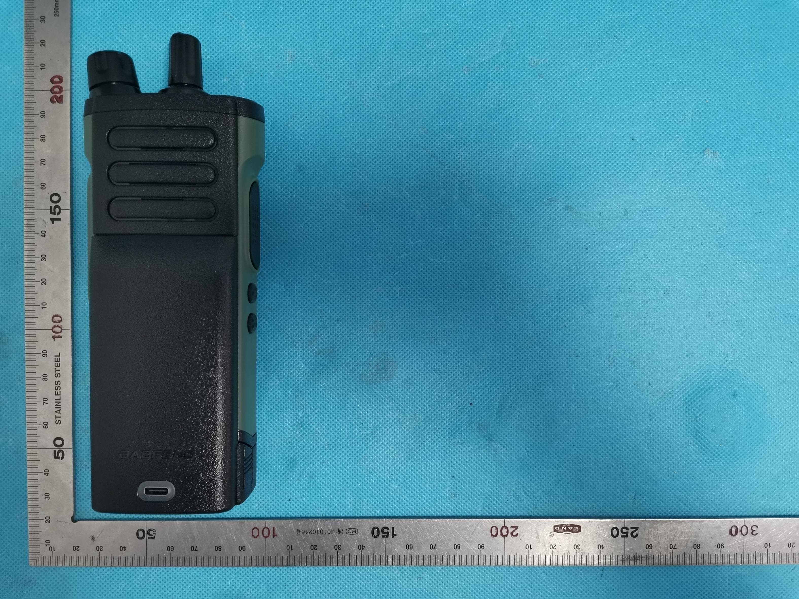
2AJGM-M4Two Way Radio
PO FUNG ELECTRONIC (HK) INTERNATONAL GROUP COMPANY LIMITED
Click to zoom
Application Details
- Equipment Class
- TNF - Licensed Non-Broadcast Transmitter Held to Face
- Date of Grant
- Dec 29, 2025
- Application Purpose
- Original Equipment
- Equipment Note
- Two Way Radio
- Frequency Range
- 400.00000000 - 406.00000000
- Country
- Hong Kong
Documents & Files
Document Text
Text extracted from the exhibit documents filed with the FCC. Open a document above to read the original.
Users Manual
M4 Series Two-way Radios OWNER’S MANUAL English Preface To help you ward off bodily injury or property loss that may arise from improper operation, please read all the information carefully before using our products. Intended Use Our products are designed to provide reliable wireless communication services for users across many industry sectors. In order to use the products safely and to achieve the best performance, they must be used as intended. The operator of the product is responsible for damage to the product or damage caused by the product if the product was used beyond the intended use instructions. Intended use includes that: ● The product is used by users who have full knowledge of its RF exposure and can exercise control over their RF exposure to meet the occupational limits in FCC/ICNIRP and international standards. ● All the security instructions set forth in this document are always heeded. ● The general, national and in-house safety regulations are heeded. ● The product is exclusively used with the frequencies licensed by the respective authority. ● The product is configured appropriately by the dealer. Besides, intended use also requires the product operator to be well-trained and to be familiar with the applicable standards, regulations and provisions. RF Radiation Information Compliance with RF Exposure Standards The radio complies with the following RF energy exposure standards and guidelines: ● United States Federal Communications Commission, Code of Federal Regulations; 47 CFR § 1.1307, 1.1310 and 2.1093 ● American National Standards Institute (ANSI) / Institute of Electrical and Electronic Engineers (IEEE) C95. 1:2005; Canada RSS102 Issue 5 March 2015 ● Institute of Electrical and Electronic Engineers (IEEE) C95.1:2005 Edition RF Exposure Compliance and Control Guidelines and Operating Instructions To control your exposure and ensure compliance with the occupational/controlled environmental exposure limits, always adhere to the following procedures. Guidelines: ● Do not remove the RF Exposure Label from the device. ● User awareness instructions should accompany device when transferred to other users. ● Do not use this device if the operational requirements described herein are not met. Operating Instructions: ● Transmit no more than the rated duty factor of 50% of the time. To transmit (talk), press the Push-to-Talk (PTT) key. To receive calls, release the PTT key. Transmitting 50% of the time, or less, is important because the radio generates measurable RF energy only when transmitting (in terms of measuring for standards compliance). ● Keep the radio unit at least 2.5 cm away from the face. Keeping the radio at the proper distance is important as RF exposure decreases with distance from the antenna. The antenna should be kept away from the face and eyes. ● When worn on the body, always place the radio in an approved holder, holster, case, or body harness or by use of the correct clip for this product. Use of non-approved accessories may result in exposure levels which exceed the FCC's occupational/controlled environmental RF exposure limits. ● Use of non-approved antennas, batteries, and accessories causes the radio to exceed the FCC RF exposure guidelines. ● Contact your local dealer for the product's optional accessories. Radiation Exposure Statement Any Changes or modifications not expressly approved by the party responsible for compliance could void the user’s authority to operate the equipment. For Remote controller, SAR tests are conducted using standard operating positions accepted by the FCC/ISEDC with the device transmitting at its highest certified power level in all tested frequency bands, although the SAR is determined at the highest certified power level, the actual SAR level of the device while operating can be well below the maximum value. Before a new model device is available for sale to the public, it must be tested and certified to the FCC that it does not exceed the exposure limit established by the FCC/ISEDC, Tests for each device are performed in positions and locations (e.g. at the ear and worn on the body) as required by the FCC/ISEDC. For body worn operation, this model device has been tested and meets the FCC/ISEDC RF exposure guidelines when used with an accessory designated for this product or when used with an accessory that Contains no metal and that positions the handset a minimum of 10 mm from the body. Non-compliance with the above restrictions may result in violation of RF exposure guidelines. Safety Information for Radios Your wireless handheld portable transceiver contains a low power transmitter. When the talk button is pushed, it sends out radio frequency (RF) signals. The device is authorized to operate at a duty factor not to exceed 50%. In August 1996, the Federal Communications Commissions(FCC) adopted RF exposure guidelines with safety levels for handheld wireless devices. This device complies with part 15 of the FCC Rules. Operation is subject to the condition that this device does not cause harmful interference. Important FCC RF Exposure Requirements: For body-worn operation, this radio has been tested and meets the FCC RF exposure guidelines when used with Pofung accessories supplied or designated for this product. Use of other accessories may not ensure compliance with FCC RF exposure guidelines. Use only the supplied antenna. Unauthorized antennas, modifications or attachments could damage the transmitter and may violate FCC regulations. FCC Regulations Federal Communication Commission (FCC) requires that all radio communication products should meet the requirements set forth in the above standards before they can be marketed in the U.S, and the manufacturer shall post a RF label on the product to inform users of operational instructions, so as to enhance their occupational health against exposure to RF energy. FCC Statement This equipment has been tested and found to comply with the limits for a Class B digital devi…
Text truncated - open the document above for the full version.
External Photos
Report No.: AGC02294250901AP02 Page 1 of 5 EXTERNAL PHOTOS All View of EUT Top View of EUT UHF Antenna Report No.: AGC02294250901AP02 Page 2 of 5 Bottom View of EUT Front View of EUT Report No.: AGC02294250901AP02 Page 3 of 5 Back View of EUT Left View of EUT Report No.: AGC02294250901AP02 Page 4 of 5 Right View of EUT Port-1 View of EUT Report No.: AGC02294250901AP02 Page 5 of 5 AC Adapter ****************************************End of Report*************************************
Test Setup Photos
Report No.: AGC02294250901AP01 Page 1 of 2 TEST SETUP PHOTOS Radiated Emission Test Setup Below 1GHz Radiated Emission Test Setup Above 1GHz Report No.: AGC02294250901AP01 Page 2 of 2 RF Conducted Test Setup ****************************************End of Report*************************************
Test Report
ReportNo.:AGC02294250901FR01 Page41of50 12.5kHz,Analogmodulation,AssignedFrequency:469.975MHz ReportNo.:AGC02294250901FR01 Page42of50 12.TransmitterFrequencyBehavior 12.1ProvisionsApplicable 47CFRFCCPART§90.214 12.2MeasurementSetup ReportNo.:AGC02294250901FR01 Page43of50 12.3MeasurementProcedure AccordingtoTIA/EIA-6032.2.19requirement,asfortheproductdifferentfromPTT,weuseteststepsas follows: 1.ConnectDUTintoTestdiscriminatorandStorageOscilloscopeandkeepDUTstatsON; 2.Input1kHzsignalintoDUT; 3.Setthemodulationdomainanalyzertotriggerontherisingedgeofthewaveforminordertocapturea 4.single-shotturn-onofthetransmittersignals; 5.KeepDUTinOFFstateandKeythePTT; 6.Observethestoredoscilloscopeofmodulationdomainanalyzer.Thesignaltraceshallbemaintained withintheallowablelimitsduringtheperiodst1andt2,andshallalsoremainwithinlimitsfollowingt2; 7.Adjustthemodulationdomainanalyzertotriggeronthefallingedgeofthetransmitterwaveforminorder tocaptureasingle-shotturn-offtransmitterofthetransmittersignal. 8.KeepthedigitalportableradioinONstateandunkeythePTT; 9.Observethestoredoscilloscopeofmodulationdomainanalyzer,Thesignaltraceshallbemaintained withintheallowablelimitsduringtheperiodt3. 10.Setthesignalgeneratortotheassignedtransmitterfrequencyandmodulateitwitha1kHztoneat±12.5 kHzdeviationandsetitsoutputlevelto-100dBm. 11.Turnonthetransmitter. 12.SupplysufficientattenuationviatheRFattenuatortoprovideaninputleveltothestoredoscilloscope thatis40dBbelowthemaximumallowedinputpowerwhenthetransmitterisoperatingatitsratedpower 13.level.NotethispowerlevelonthestoredoscilloscopeasP0. 14.Turnoffthetransmitter. 15.AdjusttheRFlevelofthesignalgeneratortoprovideRFpowerequaltoP0.ThissignalgeneratorRFlevel shallbemaintainedthroughouttherestofthemeasurement. 16.Removetheattenuation,sotheinputpowertothestoredoscilloscopeisincreasedby30dBwhenthe transmitteristurnedon. 17.Adjusttheverticalamplitudecontrolofthestoredoscilloscopetodisplaythe1000Hzat±4divisions verticallycenteredonthedisplay.SettriggermodeoftheSpectrumAnalyzerto“Video”,andtunethe “triggerlevel”onsuitablelevel.Thensetthe“tigeroffset”to-10msforturnonand-15msforturnoff. 18.TurnonthetransmitterandthetransientwavewillbecapturedonthescreenofSpectrumAnalyzer. 19.Observethestoreddisplay.Theinstantwhenthe1kHztestsignaliscompletelysuppressedis consideredtobeton.Thetraceshouldbemaintainedwithinthealloweddivisionsduringtheperiodt1and t2. 20.Thenturnoffthetransmitter,andanothertransientwavewillbecapturedonthescreenofSpectrum Analyzer.Thetraceshouldbemaintainedwithinthealloweddivisionsduringtheperiodt3. ReportNo.:AGC02294250901FR01 Page44of50 Describelimitlineoftransmitterfrequencybehavior: ton:Theswitch-oninstanttonofatransmitterisdefinedbytheconditionwhentheoutputpower, measuredattheantennaterminal,exceeds0,1%ofthefulloutputpower(-30dBc). t1:periodoftimestartingattonandfinishingaccordingtoabove11.1 t2:periodoftimestartingattheendoft1andfinishingaccordingtoabove11.1 toff:switch-offinstantdefinedbytheconditionwhentheoutputpowerfallsbelow0,1%ofthefulloutput power(-30dBc). t3:periodoftimethatfinishingattoffandstartingaccordingtoabove11.1 ReportNo.:AGC02294250901FR01 Page45of50 12.4MeasurementResult 12.5kHzChannelSeparation,Analogmodulation,AssignedFrequency:406.125MHz-TurnOn 12.5kHzChannelSeparation,Analogmodulation,AssignedFrequency:406.125MHz-TurnOff Note:Allthetestfrequencieswastested,butonlytheworstdataberecordedinthispart. ReportNo.:AGC02294250901FR01 Page46of50 13.AudioLowPassFilterResponse 13.1ProvisionsApplicable 2.1047(a):Voicemodulatedcommunicationequipment.Acurveorequivalentdatashowingthefrequency responseoftheaudiomodulatingcircuitoverarangeof100to5000Hzshallbesubmitted.Forequipment requiredtohaveanaudiolow-passfilter,acurveshowingthefrequencyresponseofthefilterorofallcircuitry installedbetweenthemodulationlimiterandthemodulatedstageshallbesubmitted. ANSITIA/EIA603-E:20163.2.15:Recommendedaudiofilterattenuationcharacteristicsaregivenbelow: Foraudiofrequenciesabove3000Hz,theaudioresponseofthepostlimiterlow-passfiltershallmeetor exceedthefollowingrequirements: a)Forequipmentoperatingon20,25or30kHzchannelbandwidthinthe25MHzto174MHzrange: Atfrequenciesfrom3000Hzthrough15,000Hztheattenuationshallbegreaterthantheattenuationat1000 Hzbyatleast:40log10(f/3000)dBwhere:fistheaudiofrequencyinHz. Atfrequenciesabove15,000Hz,theattenuationshallbegreaterthantheattenuationat1000Hz,byatleast: 28dB. b)Forequipmentoperatingwith25kHzbandwidthchannelsbetween406and512MHzthrough896MHz,and between929MHzthrough930MHz:Atfrequenciesfrom3000Hzthrough20,000Hz,theattenuationshallbe greater thantheattenuationat1000Hzbyatleast:60log10(f/3000)dBwhere:fistheaudiofrequencyinHz. Atfrequenciesabove20,000Hztheattenuationshallbegreaterthantheattenuationat1000Hzbyatleast:50 dB. c)Forequipmentoperatingonchannelsbetween896MHzthrough901MHz,between935MHzthrough940 MHz,and12.5or15kHzspacedchannelsinthefrequencyrange138-174MHzand406-512MHz. Atfrequenciesfrom3000Hzthrough20,000Hztheattenuationshallbegreaterthantheattenuationat1000 Hzbyatleast:100log10(f/3000)dBwhere:fistheaudiofrequencyinHz. ReportNo.:AGC02294250901FR01 Page47of50 13.2MeasurementProcedure Theratedaudioinputsignalwasappliedtotheinputoftheaudiolow-passfilter(orofallmodulationstages) usinganaudiooscillator,thisinputsignallevelanditscorrespondingoutputsignalwerethenmeasuredand recordedusingtheFFTDigitalSpectrumAnalyzer.Testswererepeatedatdifferentaudiosignalfrequencies from0to50kHz. TheDUTtransmitteroutputportwasconnectedtoModulationAnalyzer. 2)Pathlossforthemeasurementincluded. 3)Press23.1SPCLonmodulationanalyzertoenabletheexternalLOfromSigen. 4)SettheSigenfrequencytoFc+1.5MHz,RFoutputlevelto0dBmwithoutmodulation. 5)Transmittheradioandsettheaudioanalyzerto1kHzaudiofrequencyand60%oftheFullratedsystem deviation. 6)Uptheamplitudeby20dB. 7)OnDSA,getthereferencepointto0dB. 8)Varythefrequencyonaudioanalyzerfrom3kHzto20kHz,recordtheaudiotonefromDSA 13.3MeasurementSetup ReportNo.:AGC02294250901FR01 Page48of50 13.4MeasurementResult 12.5kHz,Analogmodulati…
Text truncated - open the document above for the full version.
Test Report
Page 1 of 50 FCCTestReport FCCID: 2AJGM-M4 APPLICATIONPURPOSE: OriginalEquipment PRODUCTDESIGNATION: TwoWayRadio BRANDNAME: BAOFENG,POFUNG,ALERVITES,ABBREE MODELNAME: M4,AT-M4,AR-M4,M7S,RD777,BF-999S,BF-878Plus APPLICANT: POFUNGELECTRONIC(HK)INTERNATONALGROUP COMPANYLIMITED DATEOFISSUE:Nov.22,2025 STANDARD(S):FCCPart90SubpartI REPORTVERSION:V1.0 AttestationofGlobalCompliance(Shenzhen)Co.,Ltd ReportNo.:AGC02294250901FR01 ReportNo.:AGC02294250901FR01 Page2of50 ReportReviseRecord ReportVersionReviseTimeIssuedDateValidVersionNotes V1.0/Nov.22,2025ValidInitialRelease ReportNo.:AGC02294250901FR01 Page3of50 TableofContents 1.GeneralInformation..........................................................................................................................................5 2.ProductInformation..........................................................................................................................................6 2.1ProductTechnicalDescription....................................................................................................................6 2.2TestFrequencyList.....................................................................................................................................7 2.3RelatedSubmittal(S)/Grant(S).................................................................................................................8 2.4TestMethodology........................................................................................................................................8 2.5CalculationofEmissionIndicators.............................................................................................................8 2.6SpecialAccessories....................................................................................................................................8 2.7EquipmentModifications.............................................................................................................................8 3.TestEnvironment..............................................................................................................................................9 3.1AddressofTheTestLaboratory..................................................................................................................9 3.2TestFacility..................................................................................................................................................9 3.3EnvironmentalConditions.........................................................................................................................10 3.4MeasurementUncertainty........................................................................................................................10 3.5ListofEquipmentUsed.............................................................................................................................11 4.SystemTestConfiguration.............................................................................................................................12 4.1EUTConfiguration....................................................................................................................................12 4.2EUTExercise............................................................................................................................................12 4.3ConfigurationofTestedSystem................................................................................................................12 4.4EquipmentUsedinTestedSystem..........................................................................................................12 4.5SummaryofTestResults..........................................................................................................................13 5.DescriptionofTestModes.............................................................................................................................14 6.FrequencyStability.........................................................................................................................................15 6.1ProvisionsApplicable................................................................................................................................15 6.2MeasurementProcedure..........................................................................................................................15 6.3MeasurementSetup..................................................................................................................................15 6.4MeasurementResult.................................................................................................................................16 7.26dBEmissionBandwidthand99%OccupiedBandwidth.......................................................................17 7.1ProvisionsApplicable................................................................................................................................17 7.2MeasurementProcedure..........................................................................................................................17 7.3MeasurementSetup..................................................................................................................................17 7.4MeasurementResult.................................................................................................................................18 8.SpuriousRadiatedEmission..........................................................................................................................20 8.1ProvisionsApplicable................................................................................................................................20 8.2MeasurementProcedure..........................................................................................................................20 8.3MeasurementSetup......................................................................…
Text truncated - open the document above for the full version.
RF Exposure Info
Page 1 of 39 SAR Test Report Report No.: AGC02294250901FH01 FCC ID : 2AJGM-M4 APPLICATION PURPOSE : Original Equipment PRODUCT DESIGNATION : Two Way Radio BRAND NAME : BAOFENG, POFUNG, ALERVITES, ABBREE MODEL NAME : M4, AT-M4, AR-M4, M7S, RD777, BF-999S, BF-878Plus APPLICANT : PO FUNG ELECTRONIC (HK) INTERNATONAL GROUP COMPANY LIMITED DATE OF ISSUE : Nov. 21, 2025 STANDARD(S) : IEEE Std. 1528:2013 FCC 47 CFR Part 2§2.1093 IEEE Std C95.1 ™-2019 REPORT VERSION : V1.0 Attestation of Global Compliance(Shenzhen) Co., Ltd. Report No.: AGC02294250901FH01 Page 2 of 39 Report Revise Record Report Version Revise Time Issued Date Valid Version Notes V1.0 / Nov. 21, 2025 Valid Initial Release Report No.: AGC02294250901FH01 Page 3 of 39 Test Report Applicant Name PO FUNG ELECTRONIC (HK) INTERNATONAL GROUP COMPANY LIMITED Applicant Address Room 1508, 15/F, Office Tower II, Grand Plaza, 625 Nathan Road, Kowloon, Hong Kong Manufacturer Name PO FUNG ELECTRONIC (HK) INTERNATONAL GROUP COMPANY LIMITED Manufacturer Address Room 1508, 15/F, Office Tower II, Grand Plaza, 625 Nathan Road, Kowloon, Hong Kong Factory Name PO FUNG ELECTRONIC (HK) INTERNATONAL GROUP COMPANY LIMITED Factory Address Room 1508, 15/F, Office Tower II, Grand Plaza, 625 Nathan Road, Kowloon, Hong Kong Product Designation Two Way Radio Brand Name BAOFENG, POFUNG, ALERVITES, ABBREE Test Model M4 Series Model AT-M4, AR-M4, M7S, RD777, BF-999S, BF-878Plus Declaration of Difference Except for differences in model names and shell line designs, everything else is the same. EUT Voltage DC 3.7V Applicable Standard IEEE Std. 1528:2013 FCC 47 CFR Part 2§2.1093 IEEE Std C95.1 ™-2019 Date of receipt of test item Sep. 03, 2025 Test Date Sep. 19, 2025 Report Template AGCRT- US -PTT/SAR (2021-04-20) Note: The results of testing in this report apply to the product/system which was tested only. Prepared By Bibo Zhang (Project Engineer) Nov. 21, 2025 Reviewed By Jack Gui (Reviewer) Nov. 21, 2025 Approved By Angela Li (Authorized Officer) Nov. 21, 2025 Report No.: AGC02294250901FH01 Page 4 of 39 TABLE OF CONTENTS 1. SUMMARY OF MAXIMUM SAR VALUE ......................................................................................................... 5 2. GENERAL INFORMATION ............................................................................................................................... 6 2.1. EUT DESCRIPTION......................................................................................................................................... 6 3. SAR MEASUREMENT SYSTEM ........................................................................................................................ 7 3.1. THE DASY5 SYSTEM USED FOR PERFORMING COMPLIANCE TESTS CONSISTS OF FOLLOWING ITEMS .................... 7 3.2. DASY5 E-FIELD PROBE ................................................................................................................................. 8 3.3. DATA ACQUISITION ELECTRONICS DESCRIPTION ............................................................................................... 8 3.4. ROBOT .......................................................................................................................................................... 9 3.5. LIGHT BEAM UNIT .......................................................................................................................................... 9 3.6. DEVICE HOLDER .......................................................................................................................................... 10 3.7. MEASUREMENT SERVER ............................................................................................................................... 10 3.8. PHANTOM ................................................................................................................................................. 11 4. SAR MEASUREMENT PROCEDURE ............................................................................................................ 12 4.1. SPECIFIC ABSORPTION RATE (SAR) .............................................................................................................. 12 4.2. SAR MEASUREMENT PROCEDURE ................................................................................................................ 13 5. TISSUE SIMULATING LIQUID ....................................................................................................................... 15 5.1. THE COMPOSITION OF THE TISSUE SIMULATING LIQUID..................................................................................... 15 5.2. TISSUE DIELECTRIC PARAMETERS FOR HEAD AND BODY PHANTOMS ............................................................... 15 5.3. TISSUE CALIBRATION RESULT ....................................................................................................................... 16 6. SAR SYSTEM CHECK PROCEDURE ........................................................................................................... 17 6.1. SAR SYSTEM CHECK PROCEDURES ............................................................................................................. 17 6.2. SAR SYSTEM CHECK ................................................................................................................................... 18 7. EUT TEST POSITION ...................................................................................................................................... 19 7.1. BODY WORN POSITION ................................................................................................................................ 19 8. SAR EXPOSURE LIMITS ............................................................................................................................... 20 9. TEST FACILITY .............................................................................................................................................. 21 10. TEST E…
Text truncated - open the document above for the full version.
RF Exposure Info
Page 1 of 18 CALIBRATION DATA PROBE CALIBRATION DATA Page 2 of 18 Page 3 of 18 Page 4 of 18 Page 5 of 18 Page 6 of 18 Page 7 of 18 Page 8 of 18 Page 9 of 18 Page 10 of 18 DAE CALIBRATION DATA Page 11 of 18 Page 12 of 18 Page 13 of 18 DIPOLE CALIBRATION DATA Page 14 of 18 Page 15 of 18 Page 16 of 18 Page 17 of 18 Page 18 of 18
Internal Photos
Report No.: AGC02294250901AP02 Page 1 of 6 INTERNAL PHOTOS Open View-1 of EUT Open View-2 of EUT Report No.: AGC02294250901AP02 Page 2 of 6 Open View-3 of EUT Internal View-1 of EUT Report No.: AGC02294250901AP02 Page 3 of 6 Internal View-2 of EUT Internal View-3 of EUT Report No.: AGC02294250901AP02 Page 4 of 6 Internal View-4 of EUT Internal View-5 of EUT Report No.: AGC02294250901AP02 Page 5 of 6 Internal View-6 of EUT Internal View-7 of EUT Report No.: AGC02294250901AP02 Page 6 of 6 Internal View-8 of EUT Battery ****************************************End of Report*************************************
ID Label/Location Info
FCC ID Label Location 30mm*30mm FCC ID: 2AJGM-M4
Attestation Statements
PO FUNG ELECTRONIC (HK) INTERNATONAL GROUP COMPANY LIMITED Room 1508, 15/F, Office Tower II, Grand Plaza, 625 Nathan Road, Kowloon, Hong Kong Attestation Statements Not Covered Entity Applicant & Not Covered Equipment To: Federal Communications Commission Date: December 3, 2025 7435 Oakland Mills Road, Columbia, MD 21046, USA Ref: Information Required by Section 2.911(d)(5)(i) & (ii) FCC ID: 2AJGM-M4 PO FUNG ELECTRONIC (HK) INTERNATONAL GROUP COMPANY LIMITED (“the applicant”) certifies that, as of the date of the filing of the application, the applicant is not identified on the Covered List, established pursuant to § 1.50002 of reference chapter, as an entity producing “covered” communication equipment. The equipment for which authorization is sought is not “covered” telecommunications equipment and video surveillance equipment produced by entities identified on the Commission’s Covered List that prohibited from receiving an equipment authorization pursuant to section § 2.903 of the FCC rules. Sincerely yours, Name: Peter Wang Title: General Manager
Cover Letter(s)
PO FUNG ELECTRONIC (HK) INTERNATONAL GROUP COMPANY LIMITED Room 1508, 15/F, Office Tower II, Grand Plaza, 625 Nathan Road, Kowloon, Hong Kong Date: 2025-12-03 FCC Part 90 Letter FEDERAL COMMUNICATIONS COMMISSION Authorization and Evaluation Division 7435 Oakland Mills Road Columbia, MD 21046 Subject: Declaration of compliance to the requirements of §90.203 w ith FCC ID: 2AJGM-M4 Dear Sir/Madam, We , PO FUNG ELECTRONIC (HK) INTERNATONAL GROUP COMPANY LIMITED acknowledge that this device will not be marketed to USA users with the frequency band which is not allowed by rule part 90.and it is a violation of FCC rules if this device is operated on unauthorized frequencies inside the U.S.A. This equipment meets the requirements of the FCC Rules, Parts 90.203(e) and (g), as applicable. Programming of this products transmit frequencies can be performed O N LY by the manufacturer or by service or by maintenance personal. The operator can’t program transmit frequencies using the equipment’s external operation controls. This is to certify that the requirements of 47 CFR Part 90.203(j)(4) and (5) spectrum efficiency are met by the PO FUNG ELECTRONIC (HK) INTERNATONAL GROUP COMPANY LIMITED demonstrated by the tests conducted on the sample radio provided. Additionally, the radio also meets the requirement of one voice channel per 12.5 kHz of channel bandwidth for analogue speech (11k0F3E emission). Sincerely Yours, Signature: __________________________ Peter Wa n g, Manager
Cover Letter(s)
PO FUNG ELECTRONIC (HK) INTERNATONAL GROUP COMPANY LIMITED Room 1508, 15/F, Office Tower II, Grand Plaza, 625 Nathan Road, Kowloon, Hong Kong (Dec. 3, 25) Federal Communications Commission Authorization and Evaluation Division 7435 Oakland Mills Road Columbia, MD 21046 Subject: Agent Authorization for FCC ID: 2AJGM-M4 I, the undersigned, hereby authorize (Attestation of Global Compliance (Shenzhen) Co., Ltd) to act on our behalf in all matters relating to this application for equipment certification. Any act carried out by (Attestation of Global Compliance (Shenzhen) Co., Ltd) shall have the same effect as our own and I acknowledge that all responsibility for complying with the terms and conditions of certification, as specified by DERYCOM CERTIFICATION SERVICES, INC., still resides with (PO FUNG ELECTRONIC (HK) INTERNATONAL GROUP COMPANY LIMITED). We certify that we are not subject to a denial of federal benefits that includes FCC benefits pursuant to Section 5301 of the Anti-Drug Abuse Act of 1988, 21 U.S.C. §862, and that no party to the application, as defined in 47 CFR §1.2002(b), is subject to a denial of federal benefits that includes FCC benefits pursuant to that section. Sincerely, (Signature) Printed Name: Peter Wang Title: General Manager Address: Room 1508, 15/F, Office Tower II, Grand Plaza, 625 Nathan Road, Kowloon, Hong Kong Tel.: 00852-90831684 Email: [email protected]
Cover Letter(s)
PO FUNG ELECTRONIC (HK) INTERNATONAL GROUP COMPANY LIMITED Room 1508, 15/F, Office Tower II, Grand Plaza, 625 Nathan Road, Kowloon, Hong Kong Office of Engineering Technology Federal Communications Commission 7435 Oakland Mills Road Columbia, MD 21046 USA Date: 2…
Text truncated - open the document above for the full version.
Contact Information
Applicant
Peter Wang
[email protected]Fax: 00852-90831684
Technical Contact
FCC US Agent, LLCTim Payne
3722 Illinois Avenue · Saint Charles, Illinois, 60174 · United States
Test Firm
Attestation of Global Compliance (Shenzhen) Co., LDoris Li
Technical Specifications
| # | Rule Parts | Frequency Range | Power Output | Emission | Tolerance |
|---|---|---|---|---|---|
| 1 | 9 | 400 MHz - 406 MHz | 1.9543 W | 5K24F3E | 1.082ppm |
| 2 | 9 | 406.1 MHz - 470 MHz | 1.9543 W | 5K24F3E | 1.082ppm |
Other Applications from PO FUNG ELECTRONIC (HK) INTERNATONAL GROUP COMPANY LIMITED
2AJGM-GM32
May 14, 2026GMRS Two Way Radio
Equipment Class
DTS - Digital Transmission System
2AJGM-AT2
Apr 13, 2026Two Way Radio
Equipment Class
DTS - Digital Transmission System
2AJGM-W31S
Dec 08, 2025Two Way Radio
Equipment Class
TNF - Licensed Non-Broadcast Transmitter Held to Face
2AJGM-888S
Oct 14, 2024TWO-WAY RADIO
Equipment Class
TNF - Licensed Non-Broadcast Transmitter Held to Face2AJGM-5RHPRO
Oct 07, 2024Amateur Radio
Equipment Class
CSR - Scanning Receiver