2AJUZ0M084LoRaWAN communication node
RuiXingHengFang Network(Shenzhen) Co., Ltd.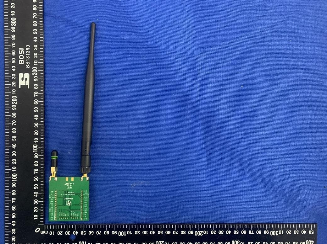
Click to zoom
Application Details
- Equipment Class
- DTS - Digital Transmission System
- Date of Grant
- Feb 17, 2022
- Application Purpose
- Original Equipment
- Date of Application
- Feb 17, 2022
- Equipment Note
- LoRaWAN communication node
- Frequency Range
- 923.30000000 - 927.50000000
- Country
- China
Documents & Files
Document Text
Text extracted from the exhibit documents filed with the FCC. Open a document above to read the original.
Users Manual
INTRODUCTION Key features: Low power consumption: as low as 2uA sleep current (WOR mode) Small size: 28mm X 23mm X 2.8mm 33 pins SMT High performance: High transmit power:: TXOP=22dBm@470MHz TXOP=22dBm@868/915MHz TXOP=13dBm@2400MHz High receiving sensitivity: 470MHz:-134 dBm sensitivity for SF12 with 125KHz BW 868MHz:-132 dBm sensitivity for SF12 with 125KHz BW 2400MHz:-130 dBm sensitivity for SF12 with 125KHz BW Interface SPI USART I2C ADC GPIO SWD Embedded LoRaWAN® protocol, AT command, support global LoRaWAN® frequency plan EU868 US915 and US915 Hybrid CN779 AU915 CN470 and CN470 Prequet AS923 KR920 IN865 Application: LoRaWAN® node Home automation applications Smart security Low-power wireless sensor network 2.4GHz remote application Function Description LoRaWAN Relay is a new defined LoRa Alliance specification, due to August 2019 official specification is still in preliminary stage. LoRaWAN relay designed by RisingHF follows LoRaWAN relay specification and add customized features like buffer mode (LoRaWAN application payload decrypted) and reserved replay mode. The LoRaWAN relay or relay mentioned in this documentation stands for RisingHF relay. LoRaWAN relay is defined to two roles, the slave and the master. During relay communication slave first send wake-up sequence (WS) to wake-up master and let master receive the WS packet, the wake-up sequence contains the following standard LoRaWAN uplink RF configuration (DR / CH). When finished WS packet receiving, master switch to uplink receiving mode to receive slave uplink with correct channel and data rate. To do it this way, slave can communicate with relay and gateway together at the same time. If uplink is successfully received, master sends on ACK to slave, slave knows uplink delivered successfully if ACK packet received, the ACK packet also contains a time synchronize information, to let slave sync it time with master to predict master’s CAD window and send shorter wake-up sequence, and thus save power. At the same time, slave keeps LoRaWAN Class A RX1 and RX2, which can be compatible with standard LoRaWAN 100%. The additional RX3 window is for relay downlink communication. Refer to LoRaWAN timing diagram for details. The RHF0M084 supports SUB-1GHz and LORA2.4G. Its communication model is shown in the figure below, and the RHF0M083 acts as a relay slave, and the RHF0M084 is simultaneously as a relay master and a LoRaWAN node. Get Started Preparation USB to TTL Serial tool x 2pcs RHF0M083 x 1pcs RHF0M084 x 1pcs LoRaWAN Gateway (maybe US915 Band) PC Serial Terminal tool (SSCOM, PUTTY, TERATERM, etc.) Relay Communication (Manual Key Mode) Before relay communication, user should select one device as master and another as slave. Configure Slave (RHF0M083) AT+DR=LR24 Or any other available band as wishes AT+RELAY=SLAVE Set device to slave mode AT+MODE=ABP AT+ID; Get slave DEVADDR Configure Master(RHF0M084) AT+DR=US915 Frequency segment for setting LoRaWAN AT+RELAY=WL,ADD,devaddr,nwkskey,appskey,relayskey (use slave’s DEVADDR/NWKSKEY/APPSKEY/RELAYSKEY) AT+RELAY=MASTER; Set device to master mode,not support slave mode Slave send packet AT+MSG=xxxxxxx Master receive packet by polling AT+RELAY=PL Enable low power mode by sending AT+LOWPOWER=AUTOON to both master and slave, after low power mode enabled, user should send four 0xFF wake up prefixes at each AT command. Relay Communication(Auto Key Mode) Before relay communication, user should select 084 device as master and 083 as slave. Configure Slave AT+DR=LR24 (Or any other available band as wishes) AT+RELAY=SLAVE Set device to slave mode AT+MODE=ABP AT+ID Get slave DEVADDR AT+KEY=AUTO Configure Master AT+DR=US915 (Frequency segment for setting LoRaWAN) Register device address to master whitelist AT+RELAY=WL,ADD,devaddr specify a single DevAddr AT+RELAY=WL,devaddr_min,devaddr_max specify device address range AT+RELAY=MASTER Set device to master mode Slave send packet AT+MSG = xxxxxxx Master receive packet by polling AT+RELAY = PL Above communication use default RootKey, if user need to specify a new RootKey use "AT+KEY=ROOTKEY, aeskey" command to overwrite default one. LoRaWAN Communication LoRaWAN communication can be performed at the same time as Relay, Configure RHF0M084 AT+DR=US915 (If you set it before, you don't need to reset it.) AT+CH = NUM , 0-7 (Set the range of subnets, and the range supported by the gateway) AT+MODE= OTAA AT+ID Get master Deveui ,Appeui Use this ID to register nodes on NS Join AT+JOIN RHF0M084 send MSG or CMSG AT+CMSG = 11111111 , AT+MSG = 22222222222 RHF0M083 send MSG to RHF0M084 ,and RHF0M084 receive packet by polling AT+RELAY=PL Advanced Application Guide Slave LoRaWAN Communication To simplify LoRaWAN relay design and increase communication system stability. The Relay implementation make trade-off on connectivity switch between relay and gateway challenge. Once configured relay slave will always try to communicate with Relay and let application user to decide which connectivity it should use (Configure through AT command). AT + MSG / CMSG / MSGHEX / CMSGHEX are still available for packet transmitting. Relay slave LoRaWAN transaction will take longer time to finish. Maximum timeout to be defined Master LoRaWAN Communication Relay master LoRaWAN communication will keep the same as standard LoRaWAN AT modem. AT + MSG / CMSG / MSGHEX / CMSGHEX are still available for relay master mode. Relay Buffer Mode Limitation Relay Buffer Mode never supports uplink frame counter which is larger than 0x3FFFFFF (67108863), it is equal to about 21 years’ time device transmitting at 10 seconds period If two master devices work closely, make sure the masters are isolated either by wake-up channel, RootKeys (Key Auto mode), or register device to different master (manual mode). In a word, whitelist or wake-up channel of the two masters must be carefully designed. Relay Buffer Mode master doesn’t send ACK to slave device Relay Buffer Mode doesn’t support ADR Relay Buffer Mode suppo…
Text truncated - open the document above for the full version.
Cover Letter(s)
RuixingHengfang Network (Shenzhen) Co., Ltd. Agent Authorization Company: RuixingHengfang Network (Shenzhen) Co., Ltd. Address: Room 201, building 6 Software Park(Phase 1), Gaoxin Mid 3rd Road, Science and Technology Park, NanShan District, Shenzhen, Guangdong, China 518017 Product Name: LoRaWAN communication node Model Number(s): RHF0M084 Product Description: LoRaWAN communication node We authorize MiCOM Labs Inc., 575 Boulder Court, Pleasanton, California 94566, USA, to act on our behalf on all matters concerning the certification of above named equipment. We declare that MiCOM Labs Inc. is allowed to forward all information related to the approval and certification of equipment to the regulatory agencies as required and to discuss any issues concerning the approval application. Any and all acts carried out by MiCOM Labs on our behalf shall have the same effect as acts of our own. Signature: Date: 2022-01-18 Name: Leo Xie Title: Manager Company: RuixingHengfang Network (Shenzhen) Co., Ltd.
Cover Letter(s)
ModularApprovalRequestFCC(KDB996369D01&Part15.212) FCCID:__2AJUZ0M084_ ItemstobecoveredbySinglemodulartransmitters. Answerfromapplicant 1.ThemodulartransmittermusthaveitsownRFshielding.Yes,theEUThasbeen shielded,pleasereferthe EUTphotos. 2.Themodulartransmittermusthavebufferedmodulation/datainputs(ifsuch inputsareprovided)toensurethatthemodulewillcomplywithPart15 requirementsunderconditionsofexcessivedataratesorover-modulation. Yes,themodulardatainputs arebufferedthroughlogor microcontrollerconnections. Allmodulationanddata inputs arebufferedbycircuitryon thetransmitterchip 3.Themodulartransmittermusthaveitsownpowersupplyregulation.Yes,Powersupplyregulation isprovidedbycircuitryonthe CPUchip 4.ThemodulartransmittermustcomplywiththeantennarequirementsofSection 15.203and15.204(b)(c).Theantennamusteitherbepermanentlyattachedor employa“unique”antennacoupler(atallconnectionsbetweenthemoduleand theantenna,includingthecable). Yes,TheEUTmeettheFCC antennarequirements 5.Themodulartransmittermustbetestedinastand-aloneconfiguration,i.e.,the modulemustnotbeinsideanotherdeviceduringtesting.Thisisintendedto demonstratethatthemoduleiscapableofcomplyingwithPart15emissionlimits regardlessofthedeviceintowhichitiseventuallyinstalled. Yes,TheEUTiscan transmittingStand-alone, pleasereferthetestsetup photos 6.Themodulartransmittermustbeequippedwitheitherapermanentlyaffixedlabel ormustbecapableofelectronicallydisplayingitsFCCidentificationnumberin accordancewith15.212(a)(1)(vi)(A)/(B). Yes,Themoduleislabeled withitspermanentlyaffixed FCCIDlabel. 7.Themodulartransmittermustcomplywithanyspecificruleoroperating requirementsapplicabletothetransmitterandthemanufacturermustprovide adequateinstructionsalongwiththemoduletoexplainanysuchrequirements.A copyoftheseinstructionsmustbeincludedintheapplicationforequipment authorization.Forexample,thereareverystrictoperationalandtiming requirementsthatmustbemetbeforeatransmitterisauthorizedforoperationunder Section15.231.Forinstance,datatransmissionisprohibited,exceptforoperation underSection15.231(e),inwhichcasethereareseparatefieldstrengthleveland timingrequirements.Compliancewiththeserequirementsmustbeassured. Yes,TheEUTisfullcompliant withFCCrules 8.ThemodulartransmittermustcomplywithanyapplicableRFexposure requirements.Forexample,FCCRulesinSections1.1310,2.1091,2.1093,and specificSectionsofPart15,including15.319(i),15.407(f),15.253(f)and 15.255(g),requirethatUnlicensedPCS,UNIIandmillimeterwavedevices performroutineenvironmentalevaluationforRFExposuretodemonstrate compliance.Inaddition,spreadspectrumtransmittersoperatingunderSection 15.247arerequiredtoaddressRFExposurecompliance.Modulartransmitters approvedunderotherSectionsofPart15,whennecessary,mayalsoneedto addresscertainRFExposureconcerns,typicallybyprovidingspecificinstallation andoperatinginstructionsforusers,installersandotherinterestedpartiesto ensurecompliance. Yes,Thismoduleiscomplies withFCCCFR47part2.1091 andFCCKDB447498D01 GeneralRFExposure Guidancev06limit,Please referRFexposurereport. ItemstobecoveredbySplitmodulartransmitters. Answerfromapplicant 1.Themodulartransmittermustcomplywithallrequirementsofasinglemodular transmitterexceptforitems(1)&(5)oftheabovesinglemodularapproval requirements. 2.Onlytheradiofrontendmustbeshielded.Thephysicalcrystalandtuning capacitorsmaybelocatedexternaltotheshieldedradioelements.Theinterface betweenthesplitsectionsofthemodularsystemmustbedigitalwithaminimum signallingamplitudeof150mVpeak-to-peak. 3.Controlinformationandotherdatamaybeexchangedbetweenthetransmitter controlelementsandradiofrontend. 4.Thesectionsofasplitmodulartransmittermustbetestedinstalledinahost device(s)similartothatwhichisrepresentativeoftheplatform(s)intendedforuse. 5.Manufacturersmustensurethatonlytransmittercontrolelementsandradiofront endcomponentsthathavebeenapprovedtogetherarecapableofoperating together.Thetransmittermodulemustnotoperateunlessithasverifiedthatthe installedtransmittercontrolelementsandradiofrontendhavebeenauthorized together.Manufacturersmayusemeansincluding,butnotlimitedto,codingin hardwareandelectronicsignaturesinsoftwaretomeettheserequirements,and mustdescribethemethodsintheirapplicationforequipmentauthorization. Note:Alimitedmodularapproval(LMA)maybegrantedforsingleorsplitmodulartransmitters thatcomplypartiallywiththerequirementsabove. Nameandsurnameofapplicant(orauthorizedrepresentative):_LeoXie___ Date:____2022/1/21___________Signature:___________________________
External Photos
Annex No.: BL-SZ21C0555-AW 1 / 3 EUT EXTERNAL PHOTOS FRONT VIEW OF EUT REAR VIEW OF EUT Annex No.: BL-SZ21C0555-AW 2 / 3 FRONT VIEW OF EUT REAR VIEW OF EUT Annex No.: BL-SZ21C0555-AW 3 / 3 FRONT VIEW OF EUT Accessory- Antenna 2.4G LoRa Antenna LoRa Antenna
ID Label/Location Info
Label 1、Label Content 2、Label Location
Internal Photos
Annex No.: BL-SZ21C0555-AI 1 / 2 EUT INTERNAL PHOTOS EUT UNCOVER VIEW 1 MAIN BOARD TOP VIEW RF Chip Annex No.: BL-SZ21C0555-AI 2 / 2 MAIN BOARD REAR VIEW
RF Exposure Info
RF Exposure Evaluation for FCC ID: 2AJUZ0M084 Refer user manual this device is a LoRaWAN communication node, and this device was designed used in Mobile devices that the minimum distance between human’s body is 20cm. Based on the 47CFR 2.1091, this device belongs to Mobile device. The definition of the category as following: Mobile Derives: CFR Title 47 §2.1091(b) (b) For purposes of this section, a mobile device is defined as a transmitting device designed to be used in other than fixed locations and to generally be used in such a way that a separation distance of at least 20 centimeters is normally maintained between the transmitter’s radiating structure(s) and the body of the user or nearby persons. FCC KDB 447498 D01 General RF Exposure Guidance v06 Limit Devices operating in standalone mobile exposure conditions may contain a single transmitter or multiple transmitters that do not transmit simultaneously. A minimum test separation distance ≥ 20 cm is required between the antenna and radiating structures of the device and nearby persons to apply mobile device exposure limits. The distance must be fully supported by the operating and installation configurations of the transmitter and its antenna(s), according to the source-based time-averaged maximum power requirements of § 2.1091(d)(2). In cases where cable losses or other attenuations are applied to determine compliance, the most conservative operating configurations and exposure conditions must be evaluated. The minimum test separation distance required for a device to comply with mobile exposure conditions must be clearly identified in the installation and operating instructions, for all installation and exposure conditions, to enable users and installers to comply with RF exposure requirements. For mobile devices that have the potential to operate in portable device exposure conditions, similar to the configurations described in § 2.1091(d)(4), a KDB inquiry is required to determine the SAR test requirements for demonstrating compliance. When the categorical exclusion provision of § 2.1091(c) applies, the minimum test separation distance may be estimated, when applicable, by simple calculations according to plane-wave equivalent conditions, to ensure the transmitter and its antenna(s) can operate in manners that meet or exceed the estimated distance. The source-based time-averaged maximum radiated power, according to the maximum antenna gain, must be applied to calculate the field strength and power density required to establish the minimum test separation distance. When the estimated test separation distance becomes overly conservative and does not support compliance, MPE measurement or computational modeling may be used to determine the required minimum separation distance. According to FCC Part 1.1307, systems operating under the provisions of this section shall be operated in a manner the ensures that the public is not exposed to radio frequency energy level in excess of the commission’s guidelines. Limits for General Population/ Uncontrolled Exposure Frequency Range (MHz) Electric Field Strength(E)(V/m) Magnetic Field Strength (H)(A/m) Power Density (S)(mW/cm 2 ) 0.3-1.34 614 1.63 (100)* 1.34-30 824/f 2.19/f (180/f2)* 30-300 27.5 0.073 0.2 300-1500 f/1500 1500-100,000 1.0 MPE calculation formula Where: S = power density P = output power (mW) G = power gain of the antenna in the direction of interest relative to an isotropic radiator R = Separation distance between radiator and human body (cm) Test data 2.4G ISM Band (GFSK modulation) Mode GFSK Low Channel Middle Channel High Channel Peak Power (dBm) 7.56 5.04 6.90 Note: This report listed the worst case peak power value, please refer to RF test report for more details. LoRa Mode 927.5 MHz Low Channel Middle Channel High Channel Peak Power (dBm) 11.49 11.47 11.39 Note: This report listed the worst case peak power value, please refer to RF test report for more details. LoRa Mode 914.9 MHz Low Channel Middle Channel High Channel Peak Power (dBm) 11.71 11.56 11.38 Note: This report listed the worst case peak power value, please refer to RF test report for more details. Turn-up power Mode Range (dBm) 2.4G ISM Band (GFSK modulation) 5.00-8.00 LoRa (927.5 MHz) 11.00-12.00 LoRa (914.9 MHz) 11.00-12.50 Test result Evolution mode Maximum peak output power (dBm) Antenna Gain (typical) (dBi): Total Power (mw) Distance (cm) Limit of Power Density (mW/cm²) Power Density (mW/cm²) Verdict 2.4G ISM Band (GFSK modulation) 8.00 1.8 9.55 20 1 0.0019 Pass LoRa (927.5 MHz) 12.00 1.0 19.95 20 0.62 0.0040 Pass LoRa (914.9 MHz) 12.50 1.0 22.39 20 0.61 0.0045 Pass Collocated Power Density Calculation Note: 1. Σ(Power Density / Limit): This is a summation of [(power density for each transmitter/ antenna included in the simultaneous transmission)/ (corresponding MPE limit)], for 2.4G ISM Band (GFSK modulation)+ LoRa. 2. Both of the 2.4G ISM Band and LoRa can transmit simultaneously, the formula of calculated the MPE is CPD1 / LPD1 + CPD2 / LPD2 + ......etc. < 1 CPD = Calculation power density LPD = Limit of power density 3. The worst-case situation is 0.0084, which is less than “1”. This confirmed that the device comply with FCC 1.1310 MPE limit. 4. The LoRaWAN communication node work frequency range used is 2400 MHz ~ 2483.5 MHz, 923.3MH~ 927.5MHz the result close to the limit by the above formula so, we select worst case power to calculate the exclusion power threshold. 5. More power list please refer to RF test report. Evolution mode Frequency (MHz) Power Density/Limit Σ(Power Density / Limit) of 2.4G ISM Band (GFSK modulation) + LoRa. Verdict 2.4G ISM Band (GFSK modulation) 2405MHz~ 2480MHz 0.0019 0.0084 Pass LoRa 923.3MHz~ 927.5MHz 0.0065 Pass Conclusion: RF exposure Evaluation Results: Compliance
Test Report
Block B, 1st FL, Baisha Science and Technology Park, Shahe Xi Road, Nanshan District, Shenzhen, Guangdong, P. R. China 518055 TEL: +86-755-66850100, FAX: +86-755-61824271 Email: [email protected] www.baluntek.com 1 / 53 RF ISSUED BY Shenzhen BALUN Technology Co., Ltd. FOR LoRaWAN communication node ISSUED TO Ruixing Hengfang Network (Shenzhen) Co., Ltd Room 201, building 6 Software Park(Phase 1), Gaoxin Mid 3rd Road, Science and Technology Park, NanShan District, Shenzhen, Guangdong, China 518017 Report No.: BL-SZ21C0555-601 EUT Name: LoRaWAN communication node Tested by: Model Name: RHF0M084 Julie Zhu Brand Name: RisingHF Date Feb. 28, 2022 Test Standard: 47 CFR Part 15 Subpart C RSS-Gen Issue 5 RSS-247 Issue 2 (refer section 3.1) Approved by: FCC ID: 2AJUZ0M084 Liao Jianming ISED Number: 22005-0M084 (Technical Director) Test Conclusion: Pass Date Feb. 28, 2022 Test Date: Dec. 20, 2021 ~ Jan. 06, 2022 Date of Issue: Feb. 28, 2022 NOTE: This test report of test results only related to testing samples, which can be duplicated completely for the legal use with the approval of the applicant; it shall not be reproduced except in full, without the written approval of Shenzhen BALUN Technology Co., Ltd. Any objections should be raised within thirty days from the date of issue. To validate the report, please contact us. TEST REPORT Report No.: BL-SZ21C0555-601 2 / 53 Revision History Version Issue Date Revisions Content Rev. 01 Jan. 18, 2022 Initial Issue Rev. 02 Feb. 16, 2022 Updated applicant and manufacturer addresses Rev. 03 Feb. 22, 2022 Updated Section 2.5 Technical Information Rev. 04 Feb. 28, 2022 Change the Modulation Type TABLE OF CONTENTS 1 ADMINISTRATIVE DATA (GENERAL INFORMATION) ........................................................................ 5 1.1 Identification of the Testing Laboratory ..................................................................................... 5 1.2 Identification of the Responsible Testing Location .................................................................... 5 1.3 Laboratory Condition ................................................................................................................ 5 1.4 Announce ................................................................................................................................. 5 2 PRODUCT INFORMATION ................................................................................................................... 6 2.1 Applicant Information ................................................................................................................ 6 2.2 Manufacturer Information .......................................................................................................... 6 2.3 Factory Information ................................................................................................................... 6 2.4 General Description for Equipment under Test (EUT) ............................................................... 6 2.5 Technical Information ............................................................................................................... 7 2.6 Additional Instructions .............................................................................................................. 8 3 SUMMARY OF TEST RESULTS ........................................................................................................... 9 3.1 Test Standards ......................................................................................................................... 9 3.2 Verdict ...................................................................................................................................... 9 4 GENERAL TEST CONFIGURATIONS ................................................................................................ 10 4.1 Test Environments .................................................................................................................. 10 4.2 Test Equipment List ................................................................................................................ 10 4.3 Test Software List ................................................................................................................... 10 4.4 Measurement Uncertainty ....................................................................................................... 11 4.5 Description of Test Setup ....................................................................................................... 11 4.5.1 For Antenna Port Test ............................................................................................................ 11 4.5.2 For AC Power Supply Port Test .............................................................................................. 12 4.5.3 For Radiated Test (Below 30 MHz) ......................................................................................... 12 4.5.4 For Radiated Test (30 MHz-1 GHz) ........................................................................................ 13 Report No.: BL-SZ21C0555-601 3 / 53 4.5.5 For Radiated Test (Above 1 GHz) .......................................................................................... 14 4.6 Measurement Results Explanation Example ........................................................................... 15 4.6.1 For conducted test items: ....................................................................................................... 15 4.6.2 For radiated band edges and spurious emission test: ............................................................. 15 5 TEST ITEMS ....................................................................................................................................... 16 5.1 Antenna Requirements ........................................................................................................... 16 5.1.1 Relevant Standards ..................................................…
Text truncated - open the document above for the full version.
Test Report
Block B, 1st FL, Baisha Science and Technology Park, Shahe Xi Road, Nanshan District, Shenzhen, Guangdong, P. R. China 518055 TEL: +86-755-66850100, FAX: +86-755-61824271 Email: [email protected] www.baluntek.com 1 / 53 RF ISSUED BY Shenzhen BALUN Technology Co., Ltd. FOR LoRaWAN communication node ISSUED TO Ruixing Hengfang Network (Shenzhen) Co., Ltd Room 201, building 6 Software Park(Phase 1), Gaoxin Mid 3rd Road, Science and Technology Park, NanShan District, Shenzhen, Guangdong, China 518017 Report No.: BL-SZ21C0555-602 EUT Name: LoRaWAN communication node Tested by: Model Name: RHF0M084 Julie Zhu Brand Name: RisingHF Date Feb. 28, 2022 Test Standard: 47 CFR Part 15 Subpart C RSS-Gen Issue 5 RSS-247 Issue 2 (refer section 3.1) Approved by: FCC ID: 2AJUZ0M084 Liao Jianming ISED Number: 22005-0M084 (Technical Director) Test Conclusion: Pass Date Feb. 28, 2022 Test Date: Dec. 20, 2021 ~ Dec. 30, 2021 Date of Issue: Feb. 28, 2022 NOTE: This test report of test results only related to testing samples, which can be duplicated completely for the legal use with the approval of the applicant; it shall not be reproduced except in full, without the written approval of Shenzhen BALUN Technology Co., Ltd. Any objections should be raised within thirty days from the date of issue. To validate the report, please contact us. TEST REPORT Report No.: BL-SZ21C0555-602 2 Revision History Version Issue Date Revisions Content Rev. 01 Jan. 18, 2022 Initial Issue Rev. 02 Feb. 16, 2022 Updated applicant and manufacturer addresses Rev. 03 Feb. 22, 2022 Updated Section 2.5 Technical Information Rev. 04 Feb. 28, 2022 Change the Modulation Type TABLE OF CONTENTS 1 ADMINISTRATIVE DATA (GENERAL INFORMATION) ........................................................................ 5 1.1 Identification of the Testing Laboratory ..................................................................................... 5 1.2 Identification of the Responsible Testing Location .................................................................... 5 1.3 Laboratory Condition ................................................................................................................ 5 1.4 Announce ................................................................................................................................. 5 2 PRODUCT INFORMATION ................................................................................................................... 6 2.1 Applicant Information ................................................................................................................ 6 2.2 Manufacturer Information .......................................................................................................... 6 2.3 Factory Information ................................................................................................................... 6 2.4 General Description for Equipment under Test (EUT) ............................................................... 6 2.5 Technical Information ............................................................................................................... 7 2.6 Additional Instructions .............................................................................................................. 8 3 SUMMARY OF TEST RESULTS ........................................................................................................... 9 3.1 Test Standards ......................................................................................................................... 9 3.2 Verdict ...................................................................................................................................... 9 4 GENERAL TEST CONFIGURATIONS ................................................................................................ 10 4.1 Test Environments .................................................................................................................. 10 4.2 Test Equipment List ................................................................................................................ 10 4.3 Test Software List ................................................................................................................... 10 4.4 Measurement Uncertainty ....................................................................................................... 11 4.5 Description of Test Setup ....................................................................................................... 11 4.5.1 For Antenna Port Test ............................................................................................................ 11 4.5.2 For AC Power Supply Port Test .............................................................................................. 12 4.5.3 For Radiated Test (Below 30 MHz) ......................................................................................... 12 Report No.: BL-SZ21C0555-602 3 4.5.4 For Radiated Test (30 MHz-1 GHz) ........................................................................................ 13 4.5.5 For Radiated Test (Above 1 GHz) .......................................................................................... 13 4.6 Measurement Results Explanation Example ........................................................................... 14 4.6.1 For conducted test items: ....................................................................................................... 14 4.6.2 For radiated band edges and spurious emission test: ............................................................. 14 5 TEST ITEMS ....................................................................................................................................... 15 5.1 Antenna Requirements ........................................................................................................... 15 5.1.1 Relevant Standards ............................................................…
Text truncated - open the document above for the full version.
Test Setup Photos
Annex No.: BL-SZ21C0555-AR 1 / 6 TEST SETUP PHOTOS 1 Radiated Test Photo Below 30MHz Close-up Annex No.: BL-SZ21C0555-AR 2 / 6 30MHz-1GHz Close-up Annex No.: BL-SZ21C0555-AR 3 / 6 Above 1GHz Close-up Annex No.: BL-SZ21C0555-AR 4 / 6 2 Conducted Test Photo Conducted Test-2.4G ISM Band (GFSK modula…
Text truncated - open the document above for the full version.
Contact Information
Applicant
Leo Xie(RD and Marketing Manager)
Technical Contact
Test Firm
Shenzhen BALUN Technology Co., Ltd.Hanson Lin
[email protected]86-755-66833830
Technical Specifications
| # | Rule Parts | Frequency Range | Power Output |
|---|---|---|---|
| 2 | 15C | 923.3 MHz - 927.5 MHz | 14.10 mW |
Other Applications from RuiXingHengFang Network(Shenzhen) Co., Ltd.
2AJUZ-RHF2S027
Apr 28, 2022loT gateway base on LoRaWAN
Equipment Class
DTS - Digital Transmission System
2AJUZ0M0E5
Nov 29, 2020LoRaWAN communication node
Equipment Class
DTS - Digital Transmission System
2AJUZ-RHF2S208
Jun 28, 2020LoRa Gateway
Equipment Class
DTS - Digital Transmission System