2AJVK-WH200Rechargeable wireless Mic
Foto Electric Supply Co., INC.
Click to zoom
Application Details
- Equipment Class
- DTS - Digital Transmission System
- Date of Grant
- Dec 16, 2020
- Application Purpose
- Original Equipment
- Date of Application
- Dec 16, 2020
- Equipment Note
- Rechargeable wireless Mic
- Frequency Range
- 2402.00000000 - 2480.00000000
- Country
- United States
Documents & Files
Document Text
Text extracted from the exhibit documents filed with the FCC. Open a document above to read the original.
Users Manual
Limited Warranty SLIDE (“SLIDE”) warrants that SLIDE’s devices and accessories (the “Products”) are free from defects in material and workmanship under normal use and service for the period commencing upon the date after that date: Main Device: 1 year What is not covered? This Limited Warranty is conditioned upon proper use of the Products. This Limited Warranty does not cover: (a) defects or damage resulting from accident, misuse, abnormal use, abnormal conditions, improper storage, neglect, exposure to liquid, moisture, damp- ness, sand or dirt, or unusual physical, electrical, or electromechanical stress; (b) scratches, dents, and cosmetic damage; (c) defects or damage resulting from excessive force or use of a metallic object when pressing on a touch screen; (d) equipment that has the serial number or the enhancement data code removed, defaced, damaged, altered, or made illegible; (e) ordinary wear and tear; (f) defects or damage resulting from the use of the Products in conjunction or connection with accessories, products, or ancillary/peripheral equipment not furnished or approved by SLIDE; (g) defects or damage resulting from improper testing, operation, maintenance, installation, service, or adjustment not furnished or approved by SLIDE; (h) defects or damage resulting from external causes such as collision with an object, - sure to weather conditions, theft, blown fuse, or improper use of any electrical source; or (i) defects or damage resulting from cellular signal reception or transmission, or viruses or other software problems introduced into the Products. This Limited Warranty covers batteries only if battery capacity falls below 80% of rated capacity or the battery leaks, and this Limited Warranty does not cover any battery if (i) the battery has been charged by charging the battery; (ii) any of the seals on the battery are broken or show evidence of tampering; or (iii) the battery has been used in equipment other than the SLIDE What are SLIDE’s obligations? During the applicable warranty period, provided the Products are returned in accordance with the terms of this Limited Warranty, SLIDE will repair or replace the Products, at SLIDE’s sole option, without charge. SLIDE may, at SLIDE’s sole option, use rebuilt, reconditioned, or new parts or components when repairing any Products, or may replace Products with rebuilt, reconditioned, or new Products. SLIDE is not responsible for data loss while repairing or replacing Products. Repaired/replaced cas- es, pouches, and holsters will be warranted for a period of ninety (90) days from day of receipt. All other repaired/ replaced Products will be warranted for a period equal to the remainder of the original Limited Warranty on the original Products or for ninety (90) days from day of receipt, whichever is longer. All replaced Products, parts, components, boards, and equipment shall become the property of SLIDE. Except to any extent expressly allowed by applicable law, transfer or assignment of this Limited Warranty is prohibited. What must you do to obtain warranty service? To obtain service under this Limited Warranty, you must email SLIDE Customer Care at [email protected] to obtain your RMA, and assistance on where to deliver the Products. Then, return the Products to the designated au- thorized phone service facility in an adequate container for shipping, accompanied by the original packaging, the serial number/IMEI of the Products, and sales receipt PERFORMANCE, AND SUITABILITY OF ANY SUCH THIRD-PAR- TY SOFTWARE OR EQUIPMENT RESTS SOLELY WITH THE USER AND THE DIRECT VENDOR, OWNER, OR SUPPLIER OF SUCH THIRD-PARTY SOFTWARE OR EQUIPMENT. Nothing in the Products instructions or information shall be construed to create an express warranty of any kind with respect to the Products. No agent, employee, dealer, representative, or reseller is authorized to modify or extend this Limited Warranty or to make binding repre- sentations or claims, whether in advertising, presentations, or otherwise, on behalf of SLIDE regarding the Products or this Limited Warranty. you may also have other rights that vary from state to state. What is the procedure for resolving disputes? ALL DISPUTES WITH SLIDE ARISING IN ANY WAY FROM THIS LIMITED WARRANTY OR THE SALE, CONDITION, OR PERFOR- MANCE OF THE PRODUCTS SHALL BE RESOLVED EXCLU- SIVELY THROUGH FINAL AND BINDING ARBITRATION, AND NOT BY A COURT OR JURY. Any such dispute shall not be combined or consolidated with a dispute involving any - cally, without limitation of the foregoing, shall not under any circumstances proceed as part of a class action. The arbitration shall be conducted before a single arbitrator, whose award may not exceed, in form or amount, the relief allowed by the applicable law. The arbitration shall be conducted according to the American Arbitration As- sociation (AAA) Commercial Arbitration Rules applicable to consumer disputes. This arbitration provision is entered pursuant to the Federal Arbitration Act. The laws of the State of Florida, without reference to its choice of laws principles, shall govern the interpretation of the Limited Warranty and all disputes that are subject to this arbitra- tion provision. The arbitrator shall decide all issues of inter- pretation and application of this arbitration provision and the Limited Warranty. This arbitration provision also applies to claims against SLIDE’s employees, representatives and condition or performance. Severability. If any portion of this Limited Warranty is held to be illegal or unenforceable, such partial illegality or unenforceabil- ity shall not affect the enforceability of the remainder of the Limited Warranty. Visit us at www.slideusa.com or contact us at [email protected] or comparable proof of sale showing the original date of purchase and the seller’s name and address. The cost of shipping to an authorized phone service facility is the sole responsibility of the customer. SLIDE will cover the cost of retur…
Text truncated - open the document above for the full version.
Cover Letter(s)
Foto Electric Supply Co., INC. Agent Authorization Company: Foto Electric Supply Co., INC. Address: 1 Rewe St. Brooklyn, New York 11211, United States Product Name: Rechargeable wireless Mic Model Number(s): WH200 Trademark: Slide FCC ID: 2AJVK-WH200 We authorize MiCOM Labs Inc., 575 Boulder Court, Pleasanton, California 94566, USA, to act on our behalf on all matters concerning the certification of above named equipment. We declare that MiCOM Labs Inc. is allowed to forward all information related to the approval and certification of equipment to the regulatory agencies as required and to discuss any issues concerning the approval application. Any and all acts carried out by MiCOM Labs on our behalf shall have the same effect as acts of our own. Signature: Date: 2020/12/15 Name: Jared Melnicoff Title: Director Sourcing Company: Foto Electric Supply Co., INC.
Cover Letter(s)
Foto Electric Supply Co., INC. Office of Engineering Technology Federal Communications Commission 7435 Oakland Mills Road Columbia, MD 21046 USA Date: 2020/12/15 Subject; Request for Confidentiality FCC ID: 2AJVK-WH200 To Whom It May Concern, Pursuant to the provisions of the Commission’s rules Title 47 Sections §0.457 and §0.459, we are requesting the Commission to withhold the following attachment(s) as confidential documents from public disclosure indefinitely. These documents contain detailed system and equipment descriptions and are considered as proprietary information in operation of the equipment. The public disclosure of these documents might be harmful to our company and would give competitors an unfair advantage in the market. Schematic Diagram Block Diagram Operational Description In additional to above mentioned documents, in order to comply with the marketing regulations in Title 47 CFR §2.803 and the importation rules in Title 47 CFR §2.1204, while ensuring that business sensitive information remains confidential until the actual marketing of newly authorized devices, we request Short Term Confidentiality of the following attachment(s); User Manual For 45 days, pursuant to Public Notice DA 04-1705. OR For 180 days pursuantto KDB 726920 D01. It is our understanding that all measurement test reports, FCC ID label format and correspondence during the certification review process cannot be granted as confidential documents and this information will be available for public review once the grant of equipment authorization is issued. Sincerely, Signature: Name: Jared Melnicoff Title: Director Sourcing
External Photos
External Photos
ID Label/Location Info
10*5mm Label Location FCC ID: 2AJVK-WH200
Internal Photos
Internal Photos Antenna
RF Exposure Info
Shenzhen BCTC Testing Co., Ltd. FCC ID: 2AJVK-WH200 Portable device According to §15.247(e)(i) and §1.1307(b)(1), systems operating under the provisions of this section shall be operated in a manner that ensures that the public is not exposed to radio frequency energy level in excess of the Commission’s guidelines. According to KDB447498 D01 General RF Exposure Guidance V06 The 1-g SAR and 10-g SAR test exclusion thresholds for 100 MHz to 6 GHz at test separation distances ≤ 50 mm are determined by: [(max. power of channel, including tune-up tolerance, mW)/(min. test separation distance, mm)]·[√f(GHZ)] ≤ 3.0 for 1-g SAR and ≤ 7.5 for 10-g extremity SAR, where: • f(GHZ) is the RF channel transmit frequency in GHz • Power and distance are rounded to the nearest mW and mm before calculation • The result is rounded to one decimal place for comparison When the minimum test separation distance is < 5 mm, a distance of 5 mm is applied to determine SAR test exclusion. BT-EDR Modulation Channel Freq. (GHz) Conduct ed power (dBm) Conducte d power (mW) Tune-up power (dBm) Max tune-up power (dBm) Max tune-up power (mW) Distance (mm) Result calculatio n SAR Exclusion threshold SAR test exclusion 8DPSK2.441-1.2780.75-1±10.001.00<50.312473.00YES BT-BLE Modulation Channel Freq. (GHz) Conduct ed power (dBm) Conducte d power (mW) Tune-up power (dBm) Max tune-up power (dBm) Max tune-up power (mW) Distance (mm) Result calculatio n SAR Exclusion threshold SAR test exclusion GFSK2.402-3.6630.43-3±1-2.000.63<50.195583.00YES Conclusion: For the max result : 0.31247<3.0, the SAR testing is not required.
Test Report
No.:BCTC/RF-EMC-005Page:1of50Edition:A.2 TEST REPORT Shenzhen BCTC Testing Co., Ltd. ReportNo.:BCTC2011526697-2E Applicant:FotoElectricSupplyCo.,INC. ProductName:RechargeablewirelessMic Model/TypeRef.: WH200 TestedDate:2020-11-27to2020-12-07 IssuedDate:2020-12-08 ReportNo.: BCTC2011526697-2E No.:BCTC/RF-EMC-005Page:2of50Edition:A.2 FCC ID: 2AJVK-WH200 The test report is effective only with both signature and specialized stamp.This result(s) shown in this report refer only to the sample(s) tested. Without written approval of Shenzhen BCTC Testing Co., Ltd, this report can’t be reproduced except in full.The tested sample(s) and the sample information are provided by the client. Product Name: Rechargeable wireless Mic Trademark: Slide Model/Type Ref.: WH200 Prepared For: Foto Electric Supply Co., INC. Address: 1 Rewe St. Brooklyn, New York 11211, United States Manufacturer: Foto Electric Supply Co., INC. Address: 1 Rewe St. Brooklyn, New York 11211, United States Prepared By: Shenzhen BCTC Testing Co., Ltd. Address: 1-2/F., East of B Building, Pengzhou Industrial Park, Fuyuan 1st Road, Qiaotou, Fuyong Street, Bao'an District, Shenzhen, Guangdong, China Sample Received Date: 2020-11-27 Sample tested Date: 2020-11-27 to 2020-12-07 Issue Date: 2020-12-08 Report No.: BCTC2011526697-2E Test Standards FCC Part15.247 ANSI C63.10-2013 Test Results PASS Remark: This is Bluetooth BLE radio test report. Tested by: Approved by: Eric Yang/Project Handler Zero Zhou/Reviewer ReportNo.: BCTC2011526697-2E No.:BCTC/RF-EMC-005Page:3of50Edition:A.2 TABLE OF CONTENT Test Report Declaration Page 1. VERSION ............................................................. 5 2. TEST SUMMARY ...................................................... 6 3. MEASUREMENT UNCERTAINTY........................................ 7 4. PRODUCT INFORMATION AND TEST SETUP ............................ 8 4.1 Product Information ..................................................... 8 4.2 Test Setup Configuration ................................................ 8 4.3 Support Equipment ..................................................... 9 4.4 Channel List ........................................................... 9 4.5 Test Mode ............................................................ 10 4.6 Table of parameters of text software setting ............................... 10 5. TEST FACILITY AND TEST INSTRUMENT USED ........................ 11 5.1 Test Facility ........................................................... 11 5.2 Test Instrument Used .................................................. 11 6. CONDUCTED EMISSIONS ............................................. 13 6.1 Block Diagram Of Test Setup ........................................... 13 6.2 Limit ................................................................. 13 6.3 Test procedure ........................................................ 13 6.4 EUT operating Conditions .............................................. 13 6.5 Test Result ........................................................... 14 7. RADIATED EMISSIONS ............................................... 16 7.1 Block Diagram Of Test Setup ........................................... 16 7.2 Limit ................................................................. 17 7.3 Test procedure ........................................................ 18 7.4 EUT operating Conditions .............................................. 19 7.5 Test Result ........................................................... 20 8. RADIATED BAND EMISSION MEASUREMENT AND RESTRICTED BANDS OF OPERATION .......................................................... 24 8.1 Block Diagram Of Test Setup ........................................... 24 8.2 Limit ................................................................. 24 8.3 Test procedure ........................................................ 25 8.4 EUT operating Conditions .............................................. 25 8.5 Test Result ........................................................... 26 9. POWER SPECTRAL DENSITY TEST ................................... 27 9.1 Block Diagram Of Test Setup ........................................... 27 9.2 Limit ................................................................. 27 9.3 Test procedure ........................................................ 27 9.4 EUT operating Conditions .............................................. 27 9.5 Test Result ........................................................... 28 10. BANDWIDTH TEST ................................................... 32 10.1 Block Diagram Of Test Setup .......................................... 32 10.2 Limit ................................................................ 32 10.3 Test procedure ....................................................... 32 ReportNo.: BCTC2011526697-2E No.:BCTC/RF-EMC-005Page:4of50Edition:A.2 10.4 EUT operating Conditions ............................................. 32 10.5 Test Result .......................................................... 33 11. PEAK OUTPUT POWER TEST ......................................... 37 11.1 Block Diagram Of Test Setup .......................................... 37 11.2 Limit ................................................................ 37 11.3 Test procedure ....................................................... 37 11.4 EUT operating Conditions ............................................. 37 11.5 Test Result .......................................................... 38 12. 100 KHZ BANDWIDTH OF FREQUENCY BAND EDGE ................... 39 12.1 Block Diagram Of Test Setup .......................................... 39 12.2 Limit ................................................................ 3…
Text truncated - open the document above for the full version.
Test Report
Report No.: BCTC2011526697-2E No.:BCTC/RF-EMC-005 Page: 41 of 50 Edition:A.2 CONDUCTED EMISSION MEASUREMENT GFSK Low Channel 2402MHz Middle Channel 2440MHz High Channel 2480MHz Report No.: BCTC2011526697-2E No.:BCTC/RF-EMC-005 Page: 42 of 50 Edition:A.2 Temperature: 26°C Relative Humidity: 54% Test Mode : GFSK 2Mbps Test Voltage : DC 3.7V GFSK: Band Edge, Left Side GFSK: Band Edge, Right Side Report No.: BCTC2011526697-2E No.:BCTC/RF-EMC-005 Page: 43 of 50 Edition:A.2 CONDUCTED EMISSION MEASUREMENT GFSK Low Channel 2402MHz Middle Channel 2440MHz High Channel 2480MHz Report No.: BCTC2011526697-2E No.:BCTC/RF-EMC-005 Page: 44 of 50 Edition:A.2 13. ANTENNA REQUIREMENT 13.1 Limit 15.203 requirement: For intentional device, according to 15.203: an intentional radiator shall be designed to ensure that no antenna other than that furnished by the responsible party shall be used with the device. 13.2 Test Result The EUT antenna is PCB antenna, Antenna Gain is 0dBi, fulfill the requirement of this section. Report No.: BCTC2011526697-2E No.:BCTC/RF-EMC-005 Page: 45 of 50 Edition:A.2 14. EUT PHOTOGRAPHS EUT Photo 1 EUT Photo 2 Report No.: BCTC2011526697-2E No.:BCTC/RF-EMC-005 Page: 46 of 50 Edition:A.2 EUT Photo 3 Report No.: BCTC2011526697-2E No.:BCTC/RF-EMC-005 Page: 47 of 50 Edition:A.2 15. EUT TEST SETUP PHOTOGRAPHS Conducted emissions Report No.: BCTC2011526697-2E No.:BCTC/RF-EMC-005 Page: 48 of 50 Edition:A.2 Radiated Measurement Photos Report No.: BCTC2011526697-2E No.:BCTC/RF-EMC-005 Page: 49 of 50 Edition:A.2 Report No.: BCTC2011526697-2E No.:BCTC/RF-EMC-005 Page: 50 of 50 Edition:A.2 STATEMENT 1.The equipment lists are traceable to the national reference standards. 2.The test report can not be partially copied unless prior written approval is issued from our lab. 3.The test report is invalid without stamp of laboratory. 4.The test report is invalid without signature of person(s) testing and authorizing. 5.The test process and test result is only related to the Unit Under Test. 6.The quality system of our laboratory is in accordance with ISO/IEC17025. 7.If there is any objection to report, the client should inform issuing laboratory within 15 days from the date of receiving test report. Address: 1-2/F., East of B Building, Pengzhou Industrial Park, Fuyuan 1st Road, Qiaotou, Fuyong Street, Bao'an District, Shenzhen, Guangdong, China TEL:400-788-9558 P. C.: 518103 FAX:0755-33229357 Website:http://www.bctc-lab.com E-Mail:[email protected] ※※※※※ END ※※※※※
Test Setup Photos
Conducted emissions Radiated Measurement Photos
Contact Information
Applicant
Jared Melnicoff(Director Sourcing)
Technical Contact
Test Firm
Shenzhen BCTC Testing Co., Ltd.Sally He
[email protected]15999690624
Technical Specifications
| # | Rule Parts | Frequency Range | Power Output |
|---|---|---|---|
| 1 | 15C | 2.40 GHz - 2.48 GHz | 430.00 µW |
Other Applications from Foto Electric Supply Co., INC.
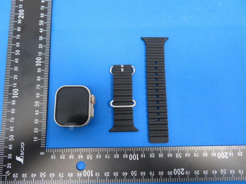
2AJVKSW475
Oct 16, 2023Smart Watch
Equipment Class
DTS - Digital Transmission System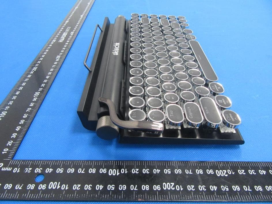
2AJVKTWKB100
Apr 02, 2023Wireless Mechanical Keyboard
Equipment Class
DTS - Digital Transmission System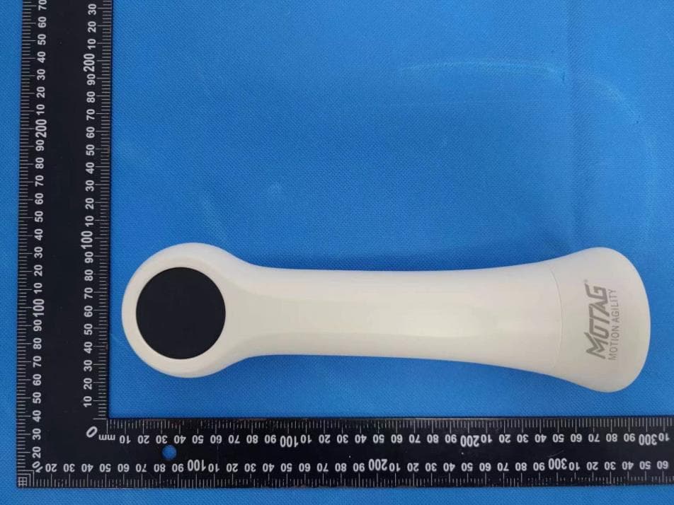
2AJVKMO-SSD5
Nov 05, 2022Smart Dumbbell
Equipment Class
DTS - Digital Transmission System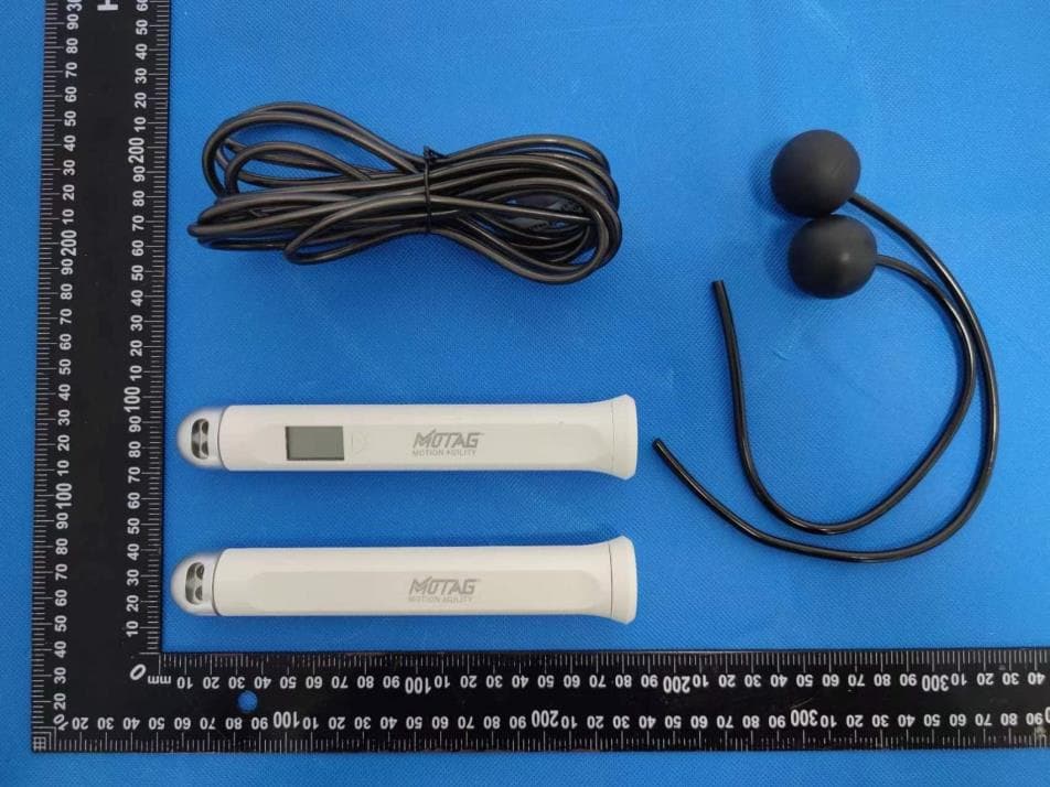
2AJVKMO-SJR
Nov 05, 2022Smart Jump Rope
Equipment Class
DTS - Digital Transmission System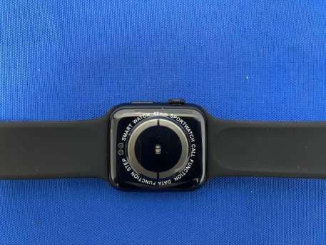
2AJVKSW375
Jul 11, 2021Smart Watch
Equipment Class
DSS - Part 15 Spread Spectrum Transmitter