2AKCY-OCS-L-P-DAcoustic Ceiling Sensor
Cooper Lighting LLC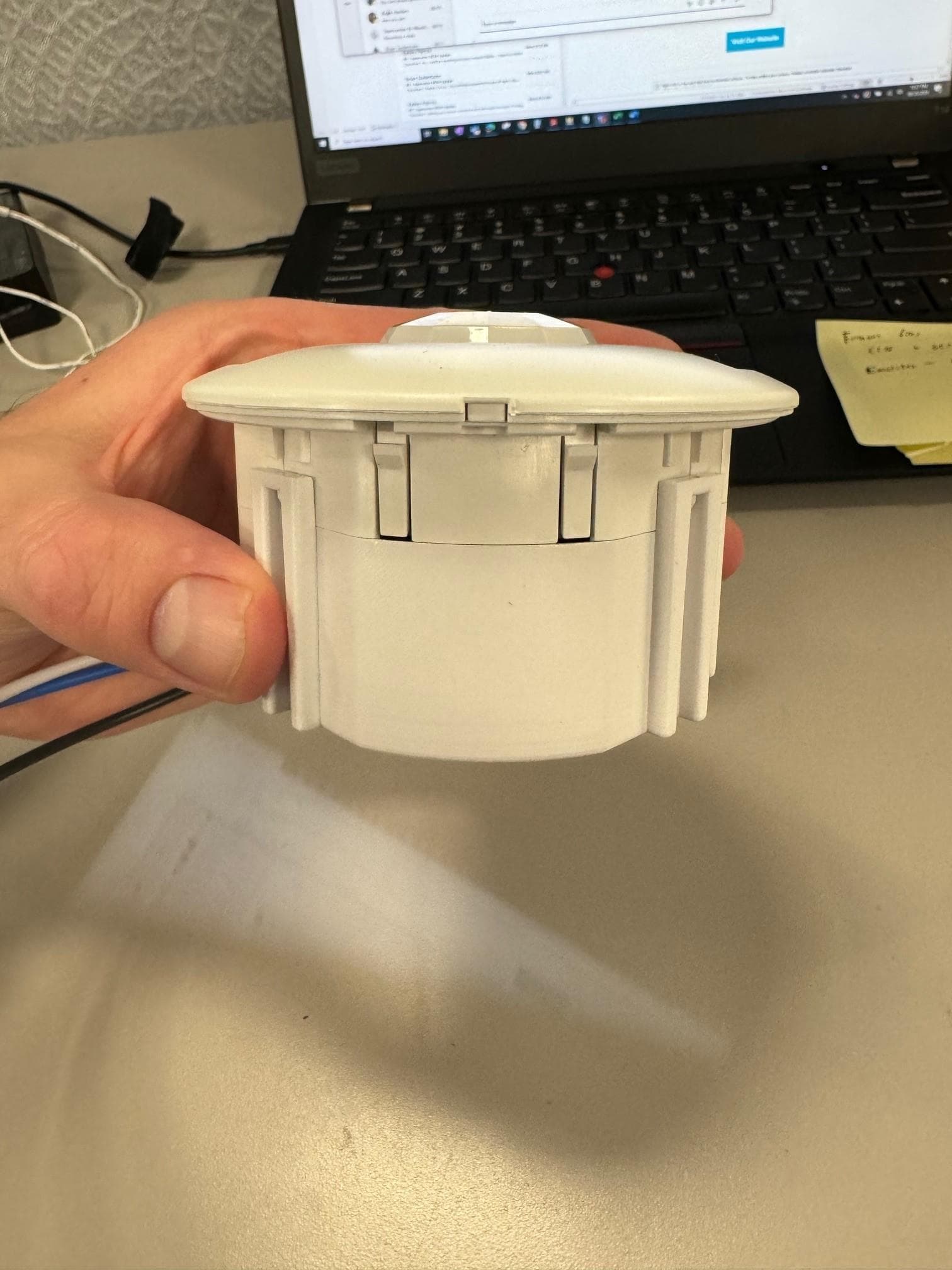
Click to zoom
Application Details
- Equipment Class
- DTS - Digital Transmission System
- Date of Grant
- Aug 15, 2024
- Application Purpose
- Original Equipment
- Date of Application
- Jul 29, 2024
- Equipment Note
- Acoustic Ceiling Sensor
- Frequency Range
- 2405.00000000 - 2480.00000000
- Company
- Cooper Lighting LLC
- Country
- United States
Documents & Files
Document Text
Text extracted from the exhibit documents filed with the FCC. Open a document above to read the original.
Users Manual
LITE WaveLinx WaveLinx LITE Line-Voltage Dual Tech Occupancy Ceiling Sensor General Information Overview The Occupancy Ceiling Sensor with passive infrared, acoustic and photocell sensors that automatically control lights with independent operation or networked operation. These sensors detect the heat from people moving within the area to determine when the space is occupied. The sensor can also detect the daylight coming into the space from the windows to determine when the fixtures near the windows should be dimmed. Supplied Parts Designed for installation on standard ceiling tiles (recess mounted within the ceiling material) or surface mounted utilizing the supplied bracket and outer bezel in conjunction with octagonal mounting box. WaveLinx LITE Line-Voltage Dual Tech Occupancy Ceiling Sensor (OCS-L-D-MV) Installation Instructions WaveLinx LITE Line-Voltage Dual Tech Occupancy Ceiling Sensor (OCS-L-D-MV) Instructions d’installation WaveLinx LITE Line-Voltage Dual Tech Occupancy Ceiling Sensor (OCS-L-D-MV) Instrucciones de Instalación Specifications Power120VAC-277VAC Mounting 4” octagon junction box or 3” hole in ceiling tile. The OCS-L requires a hole 3” [98mm] in diameter. A holesaw is recommend to create this hole. Dimension3.6”H x 3.6”W x 1.4”D (91mm x 91mm x 36mm) Coverage600, 1200 or 2000 sq. ft. at 9’ ceiling height Occupancy Detection Technology: Passive Infrared (PIR) and Acoustic Daylight Sensing Range: 0 to 300 lux Daylight Sensing Coverage: Light input within 60° cone Mobile AppConnects with WaveLinx LITE mobile app Environmental Specifications • Operating Temperature Range: 32°F to 104°F (0°C to 40°C) • Storage Temperature Range: -22°F to 158°F (-30°C to 70°C) • Relative Humidity: 5% to 85% non-condensing • For indoor use only Standards • Class 1 Input • FCC Part 15, Part C • Manufactured in an ISO 9001 certified factory • Meets ASHRAE 90.1 - 2019 requirements • Meets IECC - 2021 requirements • Meets Title 24 - 2019 requirements • RoHS Ceiling Mount 1. Sensor is designed to be installed into ceiling tile or onto a 4” Octagon. 2. Connect the Occupancy sensor per the wiring digram below. Settings can be changed through the WaveLinx LITE Mobile App. Tilemount ceiling tileceiling tile Tilemount trim ring octagon box cover octagon box adapter plate octagon box coveroctagon box adapter plate Parts not assembled J-Box 4" Octagon Junction Box with adapter plate and trim ring Canada Sales 5925 McLaughlin Road Mississauga, Ontario L5R 1B8 P: 905-501-3000 F: 905-501-3172 Cooper Lighting Solutions is a registered trademark. All trademarks are property of their respective owners. Product availability, specifications, and compliances are subject to change without notice. Cooper Lighting Solutions 1121 Highway 74 South Peachtree City, GA 30269 www.cooperlighting.com For service or technical assistance: 1-800-553-3879 © 2024 Cooper Lighting Solutions All Rights Reserved Publication No. IB50384024 July 2024 www.cooperlighting.com J-Box 4” Octagon Junction Box with adapter plate and trim ring ceiling tileceiling tile Tilemount trim ring octagon box cover octagon box adapter plate octagon box coveroctagon box adapter plate Parts not assembled J-Box 4" Octagon Junction Box with adapter plate and trim ring Wiring Diagram OCS-L-D-*-MV LINE Black White 120 VAC Hot Neutral Blue LOAD LED Definitions StateEvent Blink Pattern Occ Sensor Out of BoxMotion Detected• PIR: Green for 500 ms; Blue for 500 ms; OFF for 2 s. • MIC: Green for 500 ms; Yellow for 500 ms, Blue for 500 ms; OFF for 1.5 s. Connected Motion Detected• White for 500 ms; Blue for 500 ms; OFF for 2 s. • MIC: White for 500 ms; Yllow for 500 ms; Blue for 500 ms; OFF for 1.5 s. Identify / Reverse Identify Reverse Identification with WaveLinx Remote Magenta for 1 s; OFF for 1 sec; Repeat for identify duration ResetReset Button Pressed• Button pressed <1 s: OFF If button is released before 1 s, no reset occurs • Button pressed >= 1 s: Blue for 500 ms; OFF for 500 ms; If button is released before 5 s, soft reset begins • Button pressed >=5 s: Yellow for 500 ms; OFF for 500 ms; If button is released before 10 s, factory reset begins • Button pressed > 10 s: OFF No reset occurs Wallstation Input ButtonWallstation Input PressedThis is for the button to control vacancy mode Cyan for 500 ms; OFF for 500 ms; No Repeat If still having trouble, call Technical Services at 1-800-553-3879 Risque d’incendie, de décharge électrique, de coupure ou d’autres risques – L’installation et l’entretien de ce produit doivent être effectués par un électricien qualifié. Ce produit doit être installé conformément aux règles d’installation en vigueur par une personne familière avec la construction et le fonctionnement du produit ainsi qu’avec les risques inhérents. “L’alimentation électrique doit être HORS TENSION depuis le disjoncteur de circuit de dérivation avant de procéder à l’installation ou tout entretien. Selon la norme 240-83(d) de la NEC, si un disjoncteur de circuit de dérivation est utilisé comme interrupteur principal pour un circuit d’éclairage fluorescent, ce disjoncteur doit comporter la marque « SWD ». Toutes les installations doivent être conformes au Code national de l’électricité, ainsi qu’à tous les codes nationaux et locaux.” Risque d’incendie et de décharge électrique – Assurez-vous que l’alimentation électrique est HORS TENSION avant de commencer l’installation ou de tenter d’en faire l’entretien. Mettez l’alimentation électrique hors tension au niveau du fusible ou du disjoncteur. Toutes les installations doivent être conformes au Code national de l’électricité, ainsi qu’à tous les codes nationaux et locaux. Risque d’incendie et de décharge électrique – Assurez-vous que l’alimentation électrique est HORS TENSION avant de commencer l’installation ou de tenter d’en faire l’entretien. Mettez l’alimentation électrique hors tension depuis le fusible ou le disjoncteur. Risque de blessures – À cause des arêtes tranchantes, manipulez ce produit avec …
Text truncated - open the document above for the full version.
Users Manual
LITE WaveLinx WaveLinx LITE Low-Voltage Dual Tech Occupancy Ceiling Sensor General Information Overview The Occupancy Ceiling Sensor with passive infrared, acoustic and photocell sensors that automatically control lights with independent operation or networked operation. These sensors detect the heat from people moving within the area to determine when the space is occupied. The sensor can also detect the daylight coming into the space from the windows to determine when the fixtures near the windows should be dimmed. Supplied Parts Designed for installation on standard ceiling tiles (recess mounted within the ceiling material) or surface mounted utilizing the supplied bracket and outer bezel in conjunction with octagonal mounting box. WaveLinx LITE Low-Voltage Dual Tech Occupancy Ceiling Sensor (OCS-L-D) Installation Instructions WaveLinx LITE Low-Voltage Dual Tech Occupancy Ceiling Sensor (OCS-L-D) Instructions d’installation WaveLinx LITE Low-Voltage Dual Tech Occupancy Ceiling Sensor (OCS-L-D) Instrucciones de Instalación Specifications PowerLow Voltage 12-24VDC Mounting 4” octagon junction box or 3” hole in ceiling tile. The OCS-L requires a hole 3” [98mm] in diameter. A holesaw is recommend to create this hole. Dimension3.6”H x 3.6”W x 1.4”D (91mm x 91mm x 36mm) Coverage600, 1200 or 2000 sq. ft. at 9’ ceiling height Occupancy Detection Technology: Passive Infrared (PIR) and Acoustic Daylight Sensing Range: 0 to 300 lux Daylight Sensing Coverage: Light input within 60° cone Mobile AppConnects with WaveLinx LITE mobile app Environmental Specifications • Operating Temperature Range: 32°F to 104°F (0°C to 40°C) • Storage Temperature Range: -22°F to 158°F (-30°C to 70°C) • Relative Humidity: 5% to 85% non-condensing • For indoor use only Standards • Class 2 Input • FCC Part 15, Part C • Manufactured in an ISO 9001 certified factory • Meets ASHRAE 90.1 - 2019 requirements • Meets IECC - 2021 requirements • Meets Title 24 - 2019 requirements • RoHS Ceiling Mount 1. Sensor is designed to be installed into ceiling tile or onto a 4” Octagon. 2. Connect the Occupancy sensor per the wiring digram below. Settings can be changed through the WaveLinx LITE Mobile App. Tilemount ceiling tileceiling tile Tilemount trim ring octagon box cover octagon box adapter plate octagon box coveroctagon box adapter plate Parts not assembled J-Box 4" Octagon Junction Box with adapter plate and trim ring Canada Sales 5925 McLaughlin Road Mississauga, Ontario L5R 1B8 P: 905-501-3000 F: 905-501-3172 Cooper Lighting Solutions is a registered trademark. All trademarks are property of their respective owners. Product availability, specifications, and compliances are subject to change without notice. Cooper Lighting Solutions 1121 Highway 74 South Peachtree City, GA 30269 www.cooperlighting.com For service or technical assistance: 1-800-553-3879 © 2024 Cooper Lighting Solutions All Rights Reserved Publication No. IB50365324 July 2024 www.cooperlighting.com J-Box 4” Octagon Junction Box with adapter plate and trim ring ceiling tileceiling tile Tilemount trim ring octagon box cover octagon box adapter plate octagon box coveroctagon box adapter plate Parts not assembled J-Box 4" Octagon Junction Box with adapter plate and trim ring Risque d’incendie, de décharge électrique, de coupure ou d’autres risques – L’installation et l’entretien de ce produit doivent être effectués par un électricien qualifié. Ce produit doit être installé conformément aux règles d’installation en vigueur par une personne familière avec la construction et le fonctionnement du produit ainsi qu’avec les risques inhérents. “L’alimentation électrique doit être HORS TENSION depuis le disjoncteur de circuit de dérivation avant de procéder à l’installation ou tout entretien. Selon la norme 240-83(d) de la NEC, si un disjoncteur de circuit de dérivation est utilisé comme interrupteur principal pour un circuit d’éclairage fluorescent, ce disjoncteur doit comporter la marque « SWD ». Toutes les installations doivent être conformes au Code national de l’électricité, ainsi qu’à tous les codes nationaux et locaux.” Risque d’incendie et de décharge électrique – Assurez-vous que l’alimentation électrique est HORS TENSION avant de commencer l’installation ou de tenter d’en faire l’entretien. Mettez l’alimentation électrique hors tension au niveau du fusible ou du disjoncteur. Toutes les installations doivent être conformes au Code national de l’électricité, ainsi qu’à tous les codes nationaux et locaux. Risque d’incendie et de décharge électrique – Assurez-vous que l’alimentation électrique est HORS TENSION avant de commencer l’installation ou de tenter d’en faire l’entretien. Mettez l’alimentation électrique hors tension depuis le fusible ou le disjoncteur. Risque de blessures – À cause des arêtes tranchantes, manipulez ce produit avec précaution. AVERTISSEMENT Riesgo de incendio, descarga eléctrica, cortes u otros riesgos de accidentes- la instalación y el mantenimiento de este producto deben ser realizados por un electricista calificado. Este producto debe ser instalado de acuerdo con el código de instalación correspondiente por una persona familiarizada con la construcción y la operación del producto y los peligros involucrados. Antes de instalar o de realizar un servicio de mantenimiento, la alimentación DEBE estar APAGADA en el interruptor de potencia derivado. De conformidad con la sección 240-83(d) del NEC (Código Eléctrico Nacional), si el derivado se utiliza como interruptor principal para un circuito de iluminación fluorescente, el interruptor de potencia debe tener la marca “SWD”. Todas las instalaciones deben cumplir con el Código Eléctrico Nacional y todos los códigos locales y estatales. Riesgo de incendio y descarga eléctrica- asegúrese de que el suministro eléctrico esté desconectado antes de comenzar la instalación o intentar realizar cualquier tarea de mantenimiento. Desconecte el suministro eléctrico en el fusible o disyuntor. Todas las instalac…
Text truncated - open the document above for the full version.
Attestation Statements
Cor por ate Headquarterscooperlight ing. com 1121 Highw ay 74 Sout h Peachtree City, GA 30269 USA Classified Date: 07/30/2024 To: Federal Communications Commission Authorization and Evaluation Division 7435 Oakland Mills Road Columbia, MD 21046 USA Ref: Attestation Statements Part 2.911(d)(5)(i) and Part 2.911(d)(5)(ii) Filing Re. KDB 986446 D01 FCC ID: 2AKCY-OCS-L-P-D Dear Sir or Madam, Cooper Lighting, LLC (“the applicant”) certifies that the equipment for which authorization is sought is not “covered” equipment prohibited from receiving an equipment authorization pursuant to section 2.903 of the FCC rules. We also certify that, as of the date of the filing of the application, the applicant is not identified on the Covered List as an entity producing “covered” equipment. If you have any questions, pleas e contact us. Sincerely, Yours sincerely, Name: Chad Ruhala Title: Director of compliances Contact name: Chad Ruhala Company name: Cooper Lighting, LLC Address: 1121 Hwy 74S E-mail: [email protected] Tel: 770-407-9009
Attestation Statements
Classified To: Federal Communications Commission Authorization and Evaluation Division 7435 Oakland Mills Road Columbia, MD 21046 USA Date: 07/30/2024 Ref: Attestation Statements Part 2.911(d)(7) Filing FCC ID: 2AKCY-OCS-L-P-D Cooper Lighting, LLC (“the applicant”) certifies that, as of the date of the filing of the application, Cooper Lighting, LLC is our designated U.S. agent for service of process for the above referenced FCC ID. Cooper Lighting LLC accepts to maintain an agent for no less than one year after the grantee has terminated all marketing and importation or the conclusion of any Commission-related proceeding involving the equipment. Cooper Lighting LLC accepts, as of the date of the filing of the application, the obligation of the designated U.S. agent for service of process for the above referenced FCC ID. Designated U.S. Agent Information: Name: Cooper Lighting, LLC Address: 1121 Hwy 74 S. Contact Person: Chad Ruhala Tel.: 770-407-9009 Email: [email protected] FRN: 0026026922 Sincerely,
Cover Letter(s)
Corporate Headquarters cooperlighting.com 1121 Highw ay 74 South Peachtree City, GA 30269 USA Classified Date (06/24/2024) TUV SUD America Inc. 401 Edgewater Drive Ste 500 Wakefield MA 01880 Dear Sir or Madam, We, Cooper Lighting Solutions, hereby authorize Rossana Sarai of TUV SUD America, 5945 Cabot Parkway,Alpharetta, GA 30005 and of to act as our agent in all matters relating to applications for equipment authorization, including the signing of all documents relating to these matters. Yours sincerely, Name: Chad Ruhala Title: Director of compliances
Cover Letter(s)
Corporate Headquarters cooperlighting.com 1121 Highway 74 South Peachtree City, GA 30269 USA Classified Date (6/24/2024) Federal Communications Commission Equipment Authorization Branch 7435 Oakland Mills Road Columbia, MD 21046 Confidentiality Request FCC ID: 2AKCY-OCS-L-P-D Pursuant to Sections 0.457(d)(1)(ii) and 0.459 of the Commission’s Rules, Cooper Lighting Solutions hereby requests permanent confidential treatment of information accompanying this application as outlined below: Schematics Bill of Materials/Parts List Block Diagrams Theory of Operation The above materials contain trade secrets and proprietary information not customarily released to the public. The public disclosure of these matters might be harmful to the Applicant and provide unjustified benefits to its competitors. The Applicant understands that pursuant to Rule 0.457(d)(1)(ii), disclosure of this Application and all accompanying materials will not be made before the date of the Grant for this Application. Yours sincerely, Name: Chad Ruhala Title: Director of compliances
External Photos
Figure 1: Line Voltage Top View Figure 2: Line Voltage Side View 1 Figure 3: Line Voltage Side View 2 Figure 4: Line Voltage Bottom View Figure 5: Low Voltage Top View Figure 6: Low Voltage Side View 1 Figure 7: Low Voltage Side View 2 Figure 8: Low Voltage Bottom View
ID Label/Location Info
442296558241 OCS-L-D-06 WaveLinx LITE Low-Voltage Dual Tech Occ Ceiling Sensor 600sqft Made In Malaysia FCC ID: 2AKCY-OCS-L-P-D IC: 4706A-OCSLPD E222633 Input: 12-24 VDC, 25 mA, Class 2 Indoor 40°C 442296558211 OCS-P-D-06 WaveLinx PRO Low-Voltage Dual Tech Occ Ceiling Sensor 600sqft Made In Malaysia FCC ID: 2AKCY-OCS-L-P-D IC: 4706A-OCSLPD E222633 Input: 12-24 VDC, 25 mA, Class 2 Indoor 40°C 442296558341 OCS-L-D-12 WaveLinx LITE Low-Voltage Dual Tech Occ Ceiling Sensor 1200sqft Made In Malaysia FCC ID: 2AKCY-OCS-L-P-D IC: 4706A-OCSLPD E222633 Input: 12-24 VDC, 25 mA, Class 2 Indoor 40°C 442296558261 OCS-P-D-12 WaveLinx PRO Low-Voltage Dual Tech Occ Ceiling Sensor 1200sqft Made In Malaysia FCC ID: 2AKCY-OCS-L-P-D IC: 4706A-OCSLPD E222633 Input: 12-24 VDC, 25 mA, Class 2 Indoor 40°C 442296558611 OCS-L-D-20 WaveLinx LITE Low-Voltage Dual Tech Occ Ceiling Sensor 2000sqft Made In Malaysia FCC ID: 2AKCY-OCS-L-P-D IC: 4706A-OCSLPD E222633 Input: 12-24 VDC, 25 mA, Class 2 Indoor 40°C 442296558691 OCS-P-D-20 WaveLinx PRO Low-Voltage Dual Tech Occ Ceiling Sensor 2000sqft Made In Malaysia FCC ID: 2AKCY-OCS-L-P-D IC: 4706A-OCSLPD E222633 Input: 12-24 VDC, 25 mA, Class 2 Indoor 40°C 442296552991 OCS-L-D-06-MV WaveLinx LITE Line-Voltage Dual Tech Occ Ceiling Sensor 600sqft Made In Malaysia Output: Line Voltage Output Load: 120-277 Vac 3A General Use, 3A Standard Ballast 3A Electric Ballast, 3A Resistive 1/6 HP Motor Load FCC ID: 2AKCY-OCS-L-P-D IC: 4706A-OCSLPD E222633 Input: 120/277 VAC, 50/60 HZ, 25 mA rms Indoor 40°C 442296547661 OCS-P-D-06-MV WaveLinx PRO Line-Voltage Dual Tech Occ Ceiling Sensor 600sqft Made In Malaysia Output: Line Voltage Output Load: 120-277 Vac 3A General Use, 3A Standard Ballast 3A Electric Ballast, 3A Resistive 1/6 HP Motor Load FCC ID: 2AKCY-OCS-L-P-D IC: 4706A-OCSLPD E222633 Input: 120/277 VAC, 50/60 HZ, 25 mA rms Indoor 40°C 442296552971 OCS-L-D-12-MV WaveLinx LITE Line-Voltage Dual Tech Occ Ceiling Sensor 1200sqft Made In Malaysia Output: Line Voltage Output Load: 120-277 Vac 3A General Use, 3A Standard Ballast 3A Electric Ballast, 3A Resistive 1/6 HP Motor Load FCC ID: 2AKCY-OCS-L-P-D IC: 4706A-OCSLPD E222633 Input: 120/277 VAC, 50/60 HZ, 25 mA rms Indoor 40°C 442296553071 OCS-P-D-12-MV WaveLinx PRO Line-Voltage Dual Tech Occ Ceiling Sensor 1200sqft Made In Malaysia Output: Line Voltage Output Load: 120-277 Vac 3A General Use, 3A Standard Ballast 3A Electric Ballast, 3A Resistive 1/6 HP Motor Load FCC ID: 2AKCY-OCS-L-P-D IC: 4706A-OCSLPD E222633 Input: 120/277 VAC, 50/60 HZ, 25 mA rms Indoor 40°C 442296554491 OCS-L-D-20-MV WaveLinx LITE Line-Voltage Dual Tech Occ Ceiling Sensor 2000sqft Made In Malaysia Output: Line Voltage Output Load: 120-277 Vac 3A General Use, 3A Standard Ballast 3A Electric Ballast, 3A Resistive 1/6 HP Motor Load FCC ID: 2AKCY-OCS-L-P-D IC: 4706A-OCSLPD E222633 Input: 120/277 VAC, 50/60 HZ, 25 mA rms Indoor 40°C 442296554461 OCS-P-D-20-MV WaveLinx PRO Line-Voltage Dual Tech Occ Ceiling Sensor 2000sqft Made In Malaysia Output: Line Voltage Output Load: 120-277 Vac 3A General Use, 3A Standard Ballast 3A Electric Ballast, 3A Resistive 1/6 HP Motor Load FCC ID: 2AKCY-OCS-L-P-D IC: 4706A-OCSLPD E222633 Input: 120/277 VAC, 50/60 HZ, 25 mA rms Indoor 40°C Label Location - Line Voltage Label Location – Low Voltage
Internal Photos
Figure 1: Line Voltage Top Figure 2: Line Voltage Bottom Figure 3: Low Voltage Top Figure 4: Low Voltage Bottom
RF Exposure Info
5945 Cabot Parkway Suite 100 Alpharetta, GA 30005 USA Certification Exhibit FCC ID: 2AKCY-OCS-L-P-D FCC Rule Part: 47 CFR Part 2.1091 Project Number: 72198945 Manufacturer: COOPER LIGHTING Solutions Model Name / Number: Acoustic Ceiling Sensor / OCS-X-D-YY RF Exposure Model Name / Number: Acoustic Ceiling Sensor / OCS-X-D-YY FCC ID: 2AKCY-OCS-L-P-D Report: AT72198945-3C0 Page 2 General Information: Applicant: Cooper Lighting Solutions Device Category: Mobile Environment: General Population/Uncontrolled Exposure Technical Information (BLE) – “Device 1”: Frequency Range (MHz): 2402 - 2480 Antenna Type: Isolated Magnetic Dipole (IMD) Antenna Gains: 2.6 dBi Maximum Transmitter Conducted Power: 7.8dBm, 6.03mW Maximum System EIRP: 10.1dBm, 10.23mW Exposure Conditions: 20 centimeters Technical Information (Zigbee) – “Device 2”: Frequency Range (MHz): 2405 – 2483.5 Antenna Type: Isolated Magnetic Dipole (IMD) Antenna Gains: 2.6 dBi Maximum Transmitter Conducted Power: 7.8dBm, 6.03mW Maximum System EIRP: 10.1dBm, 10.23mW Exposure Conditions: 20 centimeters Note: The device does not support simultaneous transmissions RF Exposure Calculation Table 1: Device Characteristics (BLE & Zigbee) Technical Parameters Device 1 Device 2 Frequency (GHz) 2.402 2.405 Frequency (MHz) 2402 2405 Separation Distance (cm) 20.00 20.0 Separation Distance (m) 0.2000 0.200 Antenna Gain (dBi) 2.30 2.30 ERP Easily Determined YES YES Conducted Power (dBm) 7.80 7.80 Conducted Power (mW) 6.03 6.03 Duty Factor (Source-Based) % 100.0 100.0 Maximum (Source-Based) Time-Averaged Conducted Power (mW) 6.03 6.03 Maximum (Source-Based) Time-Averaged ERP (mW) 6.24 6.24 Maximum (Source-Based) Time-Averaged EIRP (mW) 10.23 10.23 Maximum Output (mW) 6.24 6.24 Model Name / Number: Acoustic Ceiling Sensor / OCS-X-D-YY FCC ID: 2AKCY-OCS-L-P-D Report: AT72198945-3C0 Page 3 Table 2: 47 CFR 1.1307(b)(3)(i)(c) MPE-Based Exemption ERP (W) – (BLE & Zigbee) Technical Parameters Device 1 Device 2 λ / 2π (m) 0.020 0.020 R≥ λ / 2π YES YES Maximum (Source-Based) Time-Averaged ERP (W) 0.0062 0.0062 ERP Threshold (W) 0.7680 0.7680 Exemption YES YES Contribution Ratio (ERP / ERP th ) 0.008 0.008
Test Report
Job#1587 Cooper Lighting Acoustic Ceiling Sensor Board Samples with 1001013 AntennaEvaluation Matching Change from 2.6pF to 2.7pF Rev. A.32023-12-07 San Diego Deign Center © KYOCERA AVX Components Corporation Confidential Revision History RevisionDateDescription of changes Rev A.12023-09-21Cooper Lighting Acoustic Ceiling Sensor Board Samples with 1001013 Ant Evaluation Rev A.32023-12-07Evaluation of 1001013 BT Ant Antenna performance with matching change from 2.6pF to 2.7pF for the Single PCB and Double stacked PCB per Cooper Lightingrequest Antenna P/N1001013 © KYOCERA AVX Components Corporation Confidential Summary •The purpose of this report is to Evaluate1001013 BT Antenna performance with matching change from 2.6pF to 2.7pF for the Single PCB and Double stacked PCB per Cooper Lighting’srequest tested inside plastic housing and long wires in FreeSpace. •Data Taken oReturn Loss oEfficiency oPeak Gain oRadiation Pattern © KYOCERA AVX Components Corporation Confidential Picture New Acoustic Ceiling Sensor Samples Sample New Single Board inside Plastic Housing Sample New Double Stacked Board inside Plastic Housing © KYOCERA AVX Components Corporation Confidential Picture New Sample Boards Sample New Single Board Sample New Double Stacked Board Long Wires Long Wires 1001013 Ant1001013 Ant © KYOCERA AVX Components Corporation Confidential Recommended Matching Components C36L4C37 baseline matching DNPBaseline valueBaseline value Tuned matching2.6pFZero OhmDNP New matching2.7pFZero OhmDNP Component Value Manufacturer Manufacturer Part NumberTolerance 2.7 pFKYOCERA AVX02013A2R7BAT2A±0.1pF Zero ohmPanasonic Electric CoERJ-1GE0R00CJumper Zero Ohm 2.6pF 2.7pF © KYOCERA AVX Components Corporation Confidential Test Setup –Single Board and Long Wires Z X Y 1001013 Ant Long Wires © KYOCERA AVX Components Corporation Confidential Test Setup –Double Stacked Boards and Long Wires Z X Y 1001013 Ant Long Wires © KYOCERA AVX Components Corporation Confidential Return Loss WiFi2.4G © KYOCERA AVX Components Corporation Confidential Efficiency WiFi2.4G © KYOCERA AVX Components Corporation Confidential Peak Gain WiFi2.4G © KYOCERA AVX Components Corporation Confidential Radiation Pattern: Freespace(2440MHz) © KYOCERA AVX Components Corporation Confidential Conclusion New Matching components on Copper Lighting Acoustic Ceiling Sensor Sample Boards for 1001013 Antenna inside plastic housing with long wires tested in Freespace case RF performance are summarized below: TEST DESCRIPTIONS Ave Efficiency WiFi2.4 GHz Max Pk Gain WiFi2.4 GHz 1001013 BT Ant Single PCB with 2.7pF shunt and Zero ohm in series 57 %2.32 dB 1001013 BT Ant Single PCB with 2.6pF shunt and Zero ohm in series 61 %2.55 dB 1001013 BT Ant Double Stacked PCB with 2.7pF shunt and Zero ohm in series 50 %1.57 dB 1001013 BT Ant Double Stacked PCB with 2.6pF shunt and Zero ohm in series 56 %1.69 dB Overall preference is still good, only ~4% to 6 % efficiency drop. The 2.7pF capacitor is acceptable for the change. Please refer to the slide 6 for the matching component information. © KYOCERA AVX Components Corporation KYOCERA-AVX.com THANK YOU.
Test Report
TÜV SÜD America 5945 Cabot Parkway, Suite 100 Alpharetta, GA 3005 Phone: 678-341-5900 www.tuv-sud-america.com TÜV SÜD SIGNATURE NAME JOB TITLE RESPONSIBLE FOR ISSUE DATE Thierry Jean-Charles Senior Engineer TUV SUD America Inc. Authorized Signatory 6/17/2024 Signatures in this approval box have checked this document in line with the requirements of TÜV SÜD America, Inc. document control rules. FCC Accreditation Designation Number US1233 FCC Test Site Registration Number 967699 Innovation, Science, and Economic Development Canada Lab Code 23932 EXECUTIVE SUMMARY A sample of this product was tested and found to be compliant with the standards listed above. A2LA Cert. No. 2955.09 DISCLAIMER AND COPYRIGHT This non-binding report has been prepared by TÜV SÜD America with all reasonable skill and care. The document is confidential to the potential Client and TÜV SÜD America. No part of this document may be reproduced without the prior written approval of TÜV SÜD America. © TÜV SÜD. ACCREDITATION Our A2LA Accreditation does not cover opinions and interpretations and any expressed are outside the scope of our A2LA Accreditation. Report on the Testing of the Cooper Lighting Solutions Acoustic Ceiling Sensor In accordance with: FCC 47 CFR part 15.247 ISED RSS-247 Issue 2, February 2017 Prepared for: Cooper Lighting Solutions 1121 Highway 74 South Peachtree City, GA - 30269 COMMERCIAL-IN-CONFIDENCE Document Number: AT72198945.1C1 Document Number: AT72198945.1C1 COMMERCIAL-IN-CONFIDENCE Page 2 of 43 Contents Report Summary .........................................................................................................................3 Report Modification Record ...........................................................................................................3 Introduction ....................................................................................................................................3 Brief Summary of Results .............................................................................................................5 Product Information .......................................................................................................................6 Deviations from the Standard ........................................................................................................8 EUT Modification Record ..............................................................................................................8 Test Location .................................................................................................................................9 Test Details ............................................................................................................................... 10 Antenna Requirement ................................................................................................................ 10 Power Line Conducted Emissions ............................................................................................. 11 Fundamental Emission Output Power ........................................................................................ 14 6dB / 99% Bandwidth ................................................................................................................. 17 Maximum Power Spectral Density in the Fundamental Emission ............................................. 22 Band-Edge Compliance of RF Conducted Emissions ............................................................... 25 RF Conducted Spurious Emissions ........................................................................................... 27 Radiated Spurious Emissions into Restricted Frequency Bands ............................................... 29 Test Equipment Used ................................................................................................................. 40 Diagram of Test Set-ups .......................................................................................................... 41 Accreditation, Disclaimers and Copyright............................................................................. 43 Document Number: AT72198945.1C1 COMMERCIAL-IN-CONFIDENCE Page 3 of 43 Report Summary Report Modification Record Alterations and additions to this report will be issued to the holders of each copy in the form of a complete document. Table 1.1-1 – Modification Record Issue Description of Change Date of Issue 0 First Issue 6/10/2024 1 Revised the power settings in section 1.4.3 06/17/2024 Introduction The purpose of this report is to demonstrate compliance with Part 15 Subpart C of the FCC’s Code of Federal Regulations Section 15.247 and Innovation Science and Economic Development Canada’s Radio Standards Specification RSS-247 for the tests documented herein. Applicant Sreenivas Kalathoor Manufacturer Cooper Lighting Solutions Applicant’s Email Address [email protected] Model Name Acoustic Ceiling Sensor Model Number OCS-X-D-YY Serial Number DC Model unit – P175240600119 AC Model Unit – P175240300080 FCC ID 2AKCY-OCS-L-P-D ISED Certification Number 4706A-OCSLPD Hardware Version(s) 1.0 Software Version(s) 1.0 Number of Samples Tested 1 Test Specification/Issue/Date US Code of Federal REgulation (CFR): Title 47, Part 15, Subp…
Text truncated - open the document above for the full version.
Contact Information
Applicant
Chad Ruhala(Compliance Manager)
Test Firm
TUV SUD America, Inc.William Elliott
[email protected]813-284-2736
Technical Specifications
| # | Rule Parts | Frequency Range | Power Output |
|---|---|---|---|
| 2 | 15C | 2.40 GHz - 2.48 GHz | 6.00 mW |
Other Applications from Cooper Lighting LLC
2AKCY-42296621971
Dec 08, 2025Industrial HB2 Sensor
Equipment Class
DTS - Digital Transmission System2AKCY-TSCE7
Nov 20, 20257 Inch Touchscreen
Equipment Class
DSS - Part 15 Spread Spectrum Transmitter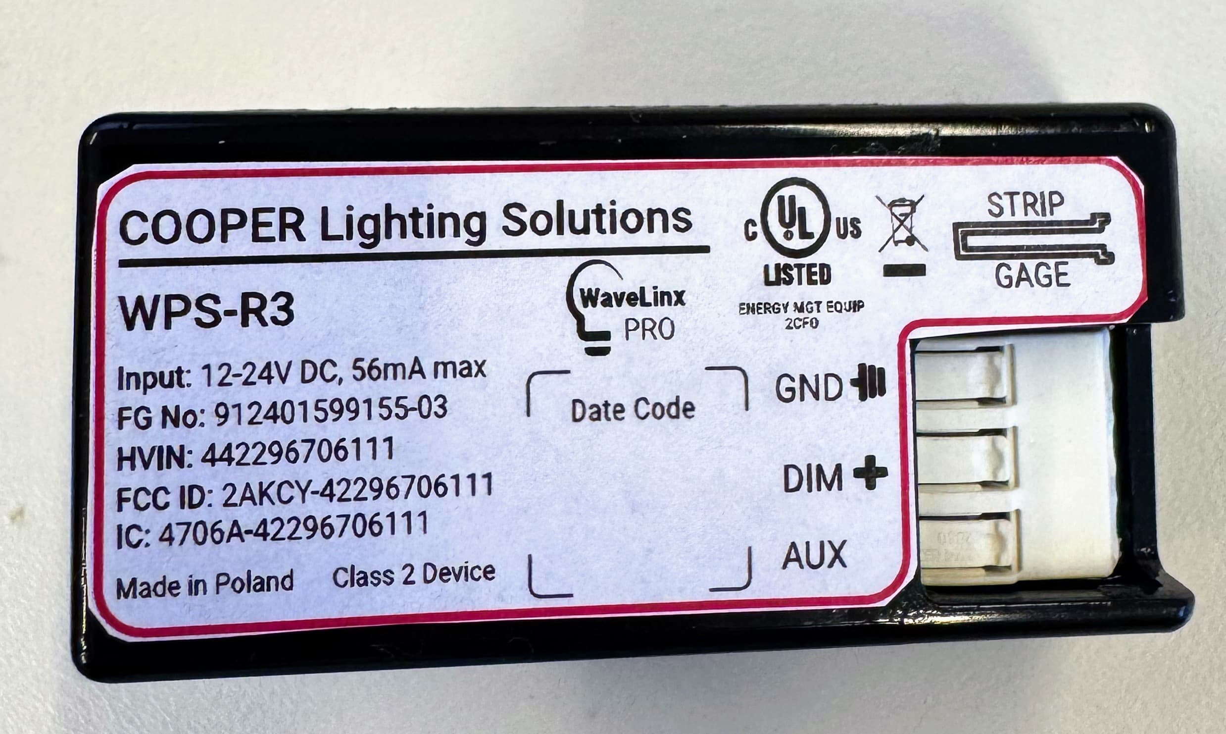
2AKCY-42296706111
Nov 17, 2025Lighting-control sensor module
Equipment Class
DTS - Digital Transmission System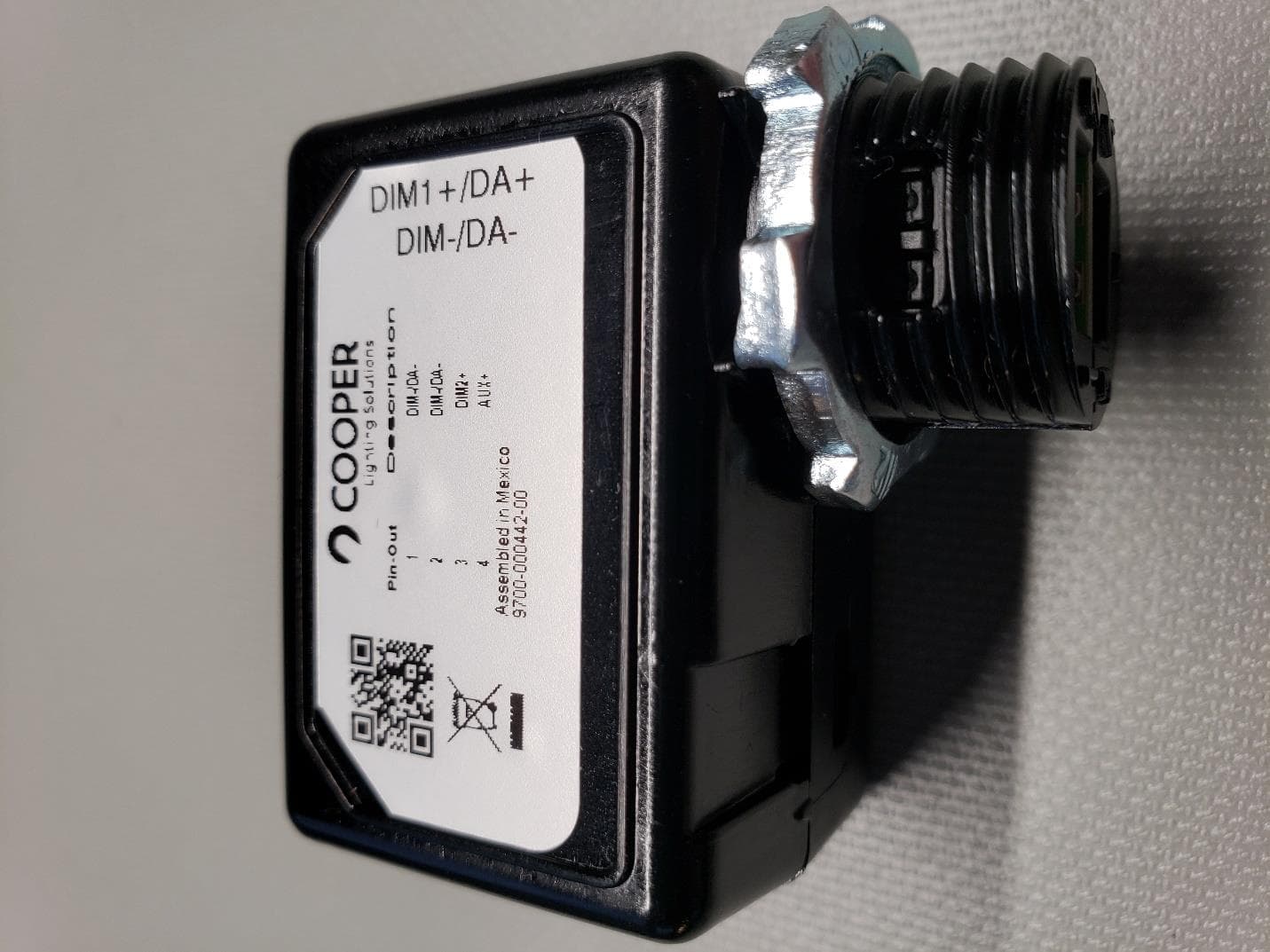
2AKCY-0028000021
Aug 04, 2022Wavelinx Pro Wireless Node
Equipment Class
DTS - Digital Transmission System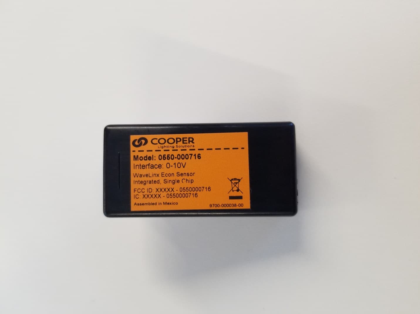
2AKCY0550000716
May 17, 2021ECON Single Chip Sensor
Equipment Class
DTS - Digital Transmission System