2AKCY0550000716ECON Single Chip Sensor
Cooper Lighting LLC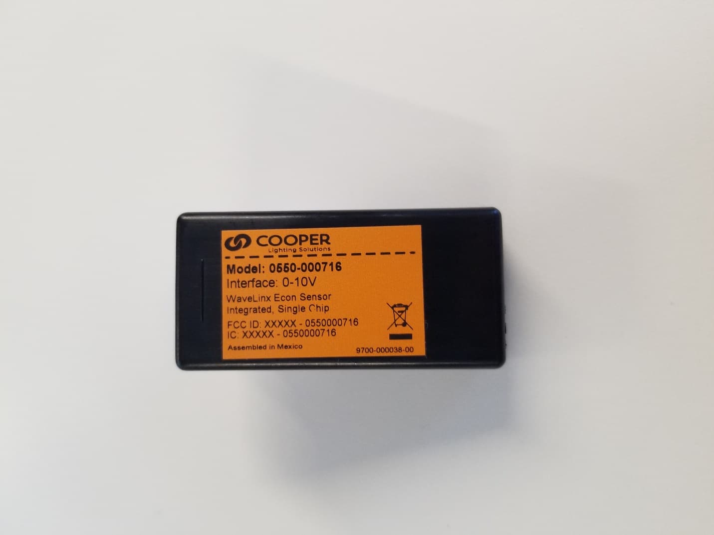
Click to zoom
Application Details
- Equipment Class
- DTS - Digital Transmission System
- Date of Grant
- May 17, 2021
- Application Purpose
- Original Equipment
- Date of Application
- May 16, 2021
- Equipment Note
- ECON Single Chip Sensor
- Frequency Range
- 2405.00000000 - 2480.00000000
- Company
- Cooper Lighting LLC
- Country
- United States
Documents & Files
Document Text
Text extracted from the exhibit documents filed with the FCC. Open a document above to read the original.
Users Manual
FCC StatementWaveLinx Cooper Lighting Solutions 1121 Highway 74 South Peachtree City, GA 30269 P: 770-486-4800 www.cooperlighting.com Canada Sales 5925 McLaughlin Road Mississauga, Ontario L5R 1B8 P: 905-501-3000 F: 905-501-3172 © 2020 Cooper Lighting Solutions All Rights Reserved Tous droits réservés Todos los derechos reservados Publication No. 9850-000709-02 March 2020 Cooper Lighting Solutions is a registered trademark. All trademarks are property of their respective owners. Cooper Lighting Solutions est une marque de commerce déposée. Toutes les autres marques de commerce sont la propriété de leur propriétaire respectif. Cooper Lighting Solutions es una marca comercial registrada. Todas las marcas comerciales son propiedad de sus respectivos propietarios. Product availability, specifications, and compliances are subject to change without notice. La disponibilité du produit, les spécifications et les conformités peuvent être modifiées sans préavis. La disponibilidad de productos, las especificaciones y los cumplimientos están sujetos a cambio sin previo aviso. FCC Statement Note: This equipment has been tested and found to comply with the limits for a Class B digital device, pursuant to part 15 of the FCC Rules. These limits are designed to provide reasonable protection against harmful interference in a residential installation. This equipment generates, uses, and can radiate radio frequency energy and, if not installed and used in accordance with the instructions, may cause harmful interference to radio communications. However, there is no guarantee that interference will not occur in a particular installation. If this equipment does cause harmful interference to radio or television reception, which can be determined by turning the equipment off and on, the user is encouraged to try to correct the interference by one or more of the following measures: • Reorient or relocate the receiving antenna. • Increase the separation between the equipment and receiver. • Connect the equipment into an outlet on a circuit different from that to which the receiver is connected. • Consult the dealer or an experienced radio/TV technician for help. FCC Part 15 Clause 15.21 Changes or modifications not expressly approved by the party responsible for compliance could void the user’s authority to operate the equipment. FCC Part 15.19a This device complies with part 15 of the FCC Rules. Operation is subject to the following two conditions: (1) This device may not cause harmful interference, and (2) this device must accept any interference received, including interference that may cause undesired operation. FCC 2.1091/RSS-102 In order to comply with FCC/ISED RF Exposure requirements, this device must be installed to provide at least 20 cm separation from the human body at all times. Declaración de la FCC Nota: El equipo ha sido probado y cumple con los límites para un dispositivo digital de Clase B, de conformidad con la parte 15 de las Normas de la FCC. Estos límites están diseñados para proporcionar una protección razonable contra las interferencias dañinas en una instalación residencial. Este equipo genera, usos y puede emitir energía de radiofrecuencia y, si no se instala y utiliza de acuerdo con las instrucciones, puede causar interferencia dañina en las comunicaciones de radio. Sin embargo, no se puede garantizar que dicha interferencia no ocurra en una instalación determinada. Si este equipo causa interferencia dañina en la recepción de radio o televisión, lo que puede determinarse apagando y encendiendo el equipo, se recomienda al usuario que intente corregir la interferencia mediante una o más de las siguientes medidas: • Reorientar o reubicar la antena receptora. • Aumentar la separación entre el equipo y el receptor. • Conectar el equipo a una toma de corriente en un circuito diferente al que está conectado el receptor • Consultar con el distribuidor o con un técnico de radio/TV experimentado para obtener ayuda. Declaración de la FCC parte 15 cláusula 15.21 Los cambios o modificaciones no aprobados expresamente por la parte responsable del cumplimiento podrían anular la autoridad del usuario para operar el equipo. Declaración de la FCC parte 15.19a Este dispositivo cumple con la parte 15 de las Reglas de la FCC. El funcionamiento está sujeto a las siguientes dos condiciones: (1) este dispositivo no puede causar interferencias perjudiciales, y (2) este dispositivo debe aceptar cualquier interferencia recibida, incluidas las interferencias que puedan causar un funcionamiento no deseado. FCC 2.1091/RSS-102 Para cumplir con los requisitos de exposición a RF de FCC / ISED, este dispositivo debe instalarse para proporcionar al menos 20 cm de separación de la cuerpo humano en todo momento. ISED RSS This device complies with Industry Canada’s licence-exempt RSSs. Operation is subject to the following two conditions: (1) This device may not cause interference; and (2) This device must accept any interference, including interference that may cause undesired operation of the device. CAN ICES-3 (B)/NMB-3(B) ISED RSS Le présent appareil est conforme aux CNR d’Industrie Canada applicables aux appareils radio exempts de licence. L’exploitation est autorisée aux deux conditions suivantes : 1) l’appareil ne doit pas produire de brouillage; 2) l’appareil doit accepter tout brouillage radioélectrique subi, même si le brouillage est susceptible d’en compromettre le fonctionnement. CAN ICES-005 (B)/NMB-005(B)
Users Manual
This document is intended for installers of the WaveLinx Lite System DISCLAIMER OF LIABILITY: Cooper Lighting Solutions assumes no liability for damages or losses of any kind that may arise from the improper, careless, or negligent installation, handling or use of the products. IMPORTANT: This manual provides information on the installation and operation of WaveLinx Lite System. For proper operation it is important to follow the installation instructions for each product/component. NOTE: WaveLinx Lite devices are not currently compatible with the WaveLinx Wireless Area Controller. ATTENTION User and Programming Manual WaveLinx Lite User Manual: WaveLinx Lite (1.5) 2 www.cooperlighting.com WaveLinx Lite User Manual - Table of contents WaveLinx Lite Architecture and General Rules ......................................................................................................................................... 5 WaveLinx Lite Communication Requirements .......................................................................................................................................... 6 WaveLinx Lite Device Reference Sheets ................................................................................................................................................... 6 Ambient Integrated Sensor Reference Sheet ....................................................................................................................................... 7 Outdoor Fixture High/Low Mount Sensor Reference Sheet................................................................................................................. 9 Line Voltage Wallstation Reference Sheet ........................................................................................................................................... 11 Logging in to the WaveLinx Lite Mobile Application ................................................................................................................................. 13 Step 1: Download and install the WaveLinx Lite Mobile Application ................................................................................................... 13 Step 2: Register for WaveLinx Lite Mobile Application Access ........................................................................................................... 14 Step 3: Login to the Mobile Application ................................................................................................................................................ 16 Mobile Application Logout................................................................................................................................................................ 17 Initial Site Setup Using the Mobile Application ......................................................................................................................................... 18 Step 1: Create a Site .............................................................................................................................................................................. 18 Step 2: Create Areas .............................................................................................................................................................................. 19 Step 3: Provision an Area’s First Device ............................................................................................................................................... 20 Step 4: Manage the Area Zones ............................................................................................................................................................ 22 Step 5: Manage the Area Occupancy Sets ........................................................................................................................................... 23 Part 1: Create New Occupancy Sets ................................................................................................................................................ 23 Part 2: Assign and Unassign Zones to Occupancy Sets ................................................................................................................. 24 Step 6: Provision Remaining Area Devices and Assign to Zones ........................................................................................................ 25 Step 7: Repeat the Process for Additional Areas ................................................................................................................................. 28 Modify Default Behavior After Provisioning .............................................................................................................................................. 29 Modify Areas .......................................................................................................................................................................................... 29 Rename an Area ................................................................................................................................................................................ 29 Delete an Area ................................................................................................................................................................................... 30 Modify Zones ......................................................................................................................................................................................... 30 Rename Zones and Update Operation Parameters ......................................................................................................................... 30 Move Devices to Different Zones ..................................................................................................................................................... 31 Delete a Zone .............................................................…
Text truncated - open the document above for the full version.
Cover Letter(s)
Cooper Lighting Solutions 1121 Highway 74 South Peachtree City, GA 30269 770 486-4800 September 18, 2020 TUV SUD America Inc. 10 Centennial Drive Peabody, MA 01960, USA Dear Sir or Madam, We, Cooper Lighting LLC at 1121 Highway 74 South hereby authorize Stan Mushyakov of TUV SUD America, 5945 Cabot Parkway, Suite 100, Alpharetta, GA 30005 and Vrajesh Patel of Cooper Lighting Solutions to act as our agent in all matters relating to applications for equipment authorization, including the signing of all documents relating to these matters. Yours sincerely, Company Officer: Chad Ruhala Telephone Number: 770-486-4168 Email: [email protected]
Cover Letter(s)
TUV SUD America, 5945 Cabot Parkway, Suite 100, Alpharetta GA 30005 Document: 120780 v1 Page 1 of 1 Date: May 14, 2021 Federal Communications Commission Laboratory 7435 Oakland Mills Road Columbia, MD 21046 Re: FCC ID: 2AKCY0550000716 To Whom It May Concern: The following application is submitted on behalf of our client, Cooper Lighting LLC, for evaluation of their model 0550-000716 for an original certification under FCC Part 15.247. Device is Cooper Lighting Solution’s next generation sensor; it provides daylight dimming, occupancy and control for connected luminaires. I have reviewed the application and supporting documentation and have found them to comply with FCC requirements. I recommend this application for certification. Yours sincerely Jeff Woods TUV SUD Senior Engineer
External Photos
Figure 1: Front View Figure 2: Back View Label Location Figure 3: Top View Figure 4: Bottom View Figure 5: Side View Figure 6: Side View
ID Label/Location Info
Figure 1: Sample Label Figure 2: Label Location Label Location
Internal Photos
Figure 1: Front View Figure 2: Rear View
RF Exposure Info
5945 Cabot Parkway Suite 100 Alpharetta, GA 30005 USA Certification Exhibit FCC ID: 2AKCY-0550000716 FCC Rule Part: 47 CFR Part 2.1091 Project Number: 72161430 Manufacturer: COOPER LIGHING LLC Model: 0550-000716 RF Exposure Model(s): 0550-000716 FCC ID: 2AKCY-0550000716 Report: AT72161430-3C0 Page 2 General Information: Applicant: Cooper Lighting LLC Device Category: Sensor Environment: General Population/Uncontrolled Exposure Technical Information (BLE): Antenna Type: Isolated Magnetic Dipole (IMD) Antenna Gains: BLE: Isolated Magnetic Dipole / 2.6dBi Maximum Transmitter Conducted Power: BLE: 11.3dBm, 13.49mW Maximum System EIRP: BLE: 13.9dBm, 24.54mW Exposure Conditions: 20 centimeters Technical Information (Zigbee): Antenna Type: Isolated Magnetic Dipole (IMD) Antenna Gains: Zigbee: Isolated Magnetic Dipole / 2.6dBi Maximum Transmitter Conducted Power: Zigbee: 11.4dBm, 13.80mW Maximum System EIRP: Zigbee: 14.0dBm, 25.11mW Exposure Conditions: 20 centimeters MPE Calculation The Power Density (mW/cm 2 ) is calculated as follows: S = 2 4R PG Where: S = power density (in appropriate units, e.g. mW/cm2) P = power input to the antenna (in appropriate units, e.g., mW) G = power gain of the antenna in the direction of interest relative to an isotropic radiator R = distance to the center of radiation of the antenna (appropriate units, e.g., cm) Table 1: MPE Calculation (BLE & Zigbee) Radio Transmit Frequency (MHz) Radio Power (dBm) Power Density Limit (mW/cm 2 ) Radio Power (mW) Antenna Gain (dBi) Antenna Gain (mW eq.) Distance (cm) Power Density (mW/cm 2 ) BTLE 2402 11.3 1.00 13.49 2.6 1.820 20 0.00488 Zigbee 2405 11.4 1.00 13.80 2.6 1.820 20 0.00500 Note: The device does not support simultaneous transmissions
Test Report
5945 Cabot Pkwy, Suite 100, Alpharetta, GA 30005 Test Report FCC ID: 2AKCY-0550000716 IC: 4706A-0550000716 FCC Rule Part: 15.247 ISED Canada Radio Standards Specification: RSS-247 Report Number: AT72161430-1C1 Manufacturer: COOPER LIGHING LLC Model: 0550-000716 Test Begin Date: July 16, 2020 Test End Date: March 19, 2021 Report Issue Date: May 13, 2021 FOR THE SCOPE OF ACCREDITATION UNDER Certificate Number: 2955.09 This report must not be used by the client to claim product certification, approval, or endorsement by A2LA, NIST, or any agency of the Federal Government. Prepared By: Reviewed by: Divya Adusumilli Kirby Munroe Senior Wireless Engineer Wireless / EMC Technical and Certification Manager, NA TÜV SÜD America Inc. TÜV SÜD America Inc. This test report shall not be reproduced except in full. This report may be reproduced in part with prior written consent of TÜV SÜD America Inc. The results contained in this report are representative of the sample(s) submitted for evaluation. This report contains 36 pages 5945 Cabot Pkwy, Suite 100, Alpharetta, GA 30005 TABLE OF CONTENTS 1 GENERAL ...................................................................................................................................... 3 1.1 PURPOSE ....................................................................................................................................... 3 1.2 APPLICANT INFORMATION ............................................................................................................ 3 1.3 PRODUCT DESCRIPTION ................................................................................................................ 3 1.4 TEST METHODOLOGY AND CONSIDERATIONS ............................................................................... 3 2 TEST FACILITIES ....................................................................................................................... 4 2.1 LOCATION ..................................................................................................................................... 4 2.2 LABORATORY ACCREDITATIONS/RECOGNITIONS/CERTIFICATIONS .............................................. 4 2.3 RADIATED EMISSIONS TEST SITE DESCRIPTION ............................................................................ 5 2.3.1 Semi-Anechoic Chamber Test Site – Chamber A ..................................................................... 5 2.3.2 Semi-Anechoic Chamber Test Site – Chamber B ..................................................................... 6 2.4 CONDUCTED EMISSIONS TEST SITE DESCRIPTION ......................................................................... 7 2.4.1 Conducted Emissions Test Site ................................................................................................. 7 3 APPLICABLE STANDARD REFERENCES ............................................................................. 8 4 LIST OF TEST EQUIPMENT ..................................................................................................... 8 5 SUPPORT EQUIPMENT.............................................................................................................. 9 6 EQUIPMENT UNDER TEST SETUP BLOCK DIAGRAM ..................................................... 9 7 SUMMARY OF TESTS................................................................................................................10 7.1 ANTENNA REQUIREMENT – FCC: 15.203 .....................................................................................10 7.2 POWER LINE CONDUCTED EMISSIONS – FCC: 15.207, ISED CANADA: RSS-GEN 8.8 .................10 7.2.1 Measurement Procedure .........................................................................................................10 7.2.2 Measurement Results ..............................................................................................................10 7.3 6DB / 99% BANDWIDTH – FCC: 15.247(A)(2), ISED CANADA: RSS-247 5.2(A), RSS-GEN 6.7 .12 7.3.1 Measurement Procedure .........................................................................................................12 7.3.2 Measurement Results ..............................................................................................................12 7.4 FUNDAMENTAL EMISSION OUTPUT POWER – FCC: 15.247(B)(3), ISED CANADA: RSS-247 5.4(D) .....................................................................................................................................................19 7.4.1 Measurement Procedure .........................................................................................................19 7.4.2 Measurement Results ..............................................................................................................19 7.5 EMISSION LEVELS ........................................................................................................................22 7.5.1 Emissions into Non-restricted Frequency Bands – FCC: 15.247(d); ISED Canada: RSS-247 5.5 ............................................................................................................................................22 7.5.2 Emissions into Restricted Frequency Bands – FCC: 15.205, 15.209; ISED Canada: RSS-Gen 8.9 / 8.10..................................................................................................................................24 7.6 MAXIMUM POWER SPECTRAL DENSITY IN THE FUNDAMENTAL EMISSION – FCC: 15.247(E) ISED CANADA: RSS-247 5.2(B) ............................................................................................................26 7.6.1 Measurement Procedure .........................................................................................................26 7.6.2 Measurement Results ..............................................................................................................26 8 ESTIMATION OF MEASUREMENT UNCERTAINTY ........................................................…
Text truncated - open the document above for the full version.
Test Report
5945 Cabot Pkwy, Suite 100, Alpharetta, GA 30005 Test Report FCC ID: 2AKCY-0550000716 IC: 4706A-0550000716 FCC Rule Part: 15.247 ISED Canada Radio Standards Specification: RSS-247 Report Number: AT72161430-2C1 Manufacturer: COOPER LIGHING LLC Model: 0550-000716 Test Begin Date: July 15, 2020 Test End Date: March 18, 2021 Report Issue Date: May 13, 2021 FOR THE SCOPE OF ACCREDITATION UNDER Certificate Number: 2955.09 This report must not be used by the client to claim product certification, approval, or endorsement by A2LA, NIST, or any agency of the Federal Government. Prepared By: Reviewed by: Divya Adusumilli Kirby Munroe Senior Wireless Engineer Wireless / EMC Technical and Certification Manager, NA TÜV SÜD America Inc. TÜV SÜD America Inc. This test report shall not be reproduced except in full. This report may be reproduced in part with prior written consent of TÜV SÜD America Inc. The results contained in this report are representative of the sample(s) submitted for evaluation. This report contains 41 pages 5945 Cabot Pkwy, Suite 100, Alpharetta, GA 30005 TABLE OF CONTENTS 1 GENERAL ...................................................................................................................................... 3 1.1 PURPOSE ....................................................................................................................................... 3 1.2 APPLICANT INFORMATION ............................................................................................................ 3 1.3 PRODUCT DESCRIPTION ................................................................................................................ 3 1.4 TEST METHODOLOGY AND CONSIDERATIONS ............................................................................... 3 2 TEST FACILITIES ....................................................................................................................... 4 2.1 LOCATION ..................................................................................................................................... 4 2.2 LABORATORY ACCREDITATIONS/RECOGNITIONS/CERTIFICATIONS .............................................. 4 2.3 RADIATED EMISSIONS TEST SITE DESCRIPTION ............................................................................ 5 2.3.1 Semi-Anechoic Chamber Test Site – Chamber A ..................................................................... 5 2.3.2 Semi-Anechoic Chamber Test Site – Chamber B ..................................................................... 6 2.4 CONDUCTED EMISSIONS TEST SITE DESCRIPTION ......................................................................... 7 2.4.1 Conducted Emissions Test Site ................................................................................................. 7 3 APPLICABLE STANDARD REFERENCES ............................................................................. 8 4 LIST OF TEST EQUIPMENT ..................................................................................................... 8 5 SUPPORT EQUIPMENT.............................................................................................................. 9 6 EQUIPMENT UNDER TEST SETUP BLOCK DIAGRAM ..................................................... 9 7 SUMMARY OF TESTS................................................................................................................10 7.1 ANTENNA REQUIREMENT – FCC: 15.203 .....................................................................................10 7.2 POWER LINE CONDUCTED EMISSIONS – FCC: 15.207, ISED CANADA: RSS-GEN 8.8 .................10 7.2.1 Measurement Procedure .........................................................................................................10 7.2.2 Measurement Results ..............................................................................................................10 7.3 6DB / 99% BANDWIDTH – FCC: 15.247(A)(2), ISED CANADA: RSS-247 5.2(A), RSS-GEN 6.7 .12 7.3.1 Measurement Procedure .........................................................................................................12 7.3.2 Measurement Results ..............................................................................................................12 7.4 FUNDAMENTAL EMISSION OUTPUT POWER – FCC: 15.247(B)(3), ISED CANADA: RSS-247 5.4(D) .....................................................................................................................................................21 7.4.1 Measurement Procedure .........................................................................................................21 7.4.2 Measurement Results ..............................................................................................................21 7.5 EMISSION LEVELS ........................................................................................................................25 7.5.1 Emissions into Non-restricted Frequency Bands – FCC: 15.247(d); ISED Canada: RSS-247 5.5 ............................................................................................................................................25 7.5.2 Emissions into Restricted Frequency Bands – FCC: 15.205, 15.209; ISED Canada: RSS-Gen 8.9 / 8.10..................................................................................................................................28 7.6 MAXIMUM POWER SPECTRAL DENSITY IN THE FUNDAMENTAL EMISSION – FCC: 15.247(E) ISED CANADA: RSS-247 5.2(B) ............................................................................................................29 7.6.1 Measurement Procedure .........................................................................................................29 7.6.2 Measurement Results ..............................................................................................................29 8 ESTIMATION OF MEASUREMENT UNCERTAINTY ........................................................…
Text truncated - open the document above for the full version.
Test Setup Photos
5945 Cabot Parkway Suite 100 Alpharetta, GA 30005 USA Certification Exhibit FCC ID: 2AKCY-0550000716 IC: 4706A-0550000716 FCC Rule Part: 15.247 ISED Canada Radio Standards Specification: RSS-247 Project Number: 72161430 Manufacturer: COOPER LIGHING LLC Model: 0550-000716 Test Setup Photos Model(s): 0550-000716 FCC ID: 2AKCY-0550000716 IC: 4706A-0550000716 Project: 72161430 Page 2 Figure 1: Equipment Under Test – Antenna Port Conducted Measurements Figure 2: Equipment Under Test – Radiated Emissions <30MHz Model(s): 0550-000716 FCC ID: 2AKCY-0550000716 IC: 4706A-0550000716 Project: 72161430 Page 3 Figure 3: Equipment Under Test – Radiated Emissions <1GHz Figure 4: Equipment Under Test – Radiated Emissions <1GHz Model(s): 0550-000716 FCC ID: 2AKCY-0550000716 IC: 4706A-0550000716 Project: 72161430 Page 4 Figure 5: Equipment Under Test – Radiated Emissions >1GHz Figure 6: Equipment Under Test – Radiated Emissions >1GHz Model(s): 0550-000716 FCC ID: 2AKCY-0550000716 IC: 4706A-0550000716 Project: 72161430 Page 5 Figure 7: Equipment Under Test – AC Conducted Emissions Figure 8: Equipment Under Test – AC Conducted Emissions
Contact Information
Applicant
Chad Ruhala(Compliance Manager)
Test Firm
TUV SUD America, Inc.William Elliott
[email protected]813-284-2736
Technical Specifications
| # | Rule Parts | Frequency Range | Power Output |
|---|---|---|---|
| 2 | 15C | 2.40 GHz - 2.48 GHz | 14.00 mW |
Other Applications from Cooper Lighting LLC
2AKCY-42296621971
Dec 08, 2025Industrial HB2 Sensor
Equipment Class
DTS - Digital Transmission System2AKCY-TSCE7
Nov 20, 20257 Inch Touchscreen
Equipment Class
DSS - Part 15 Spread Spectrum Transmitter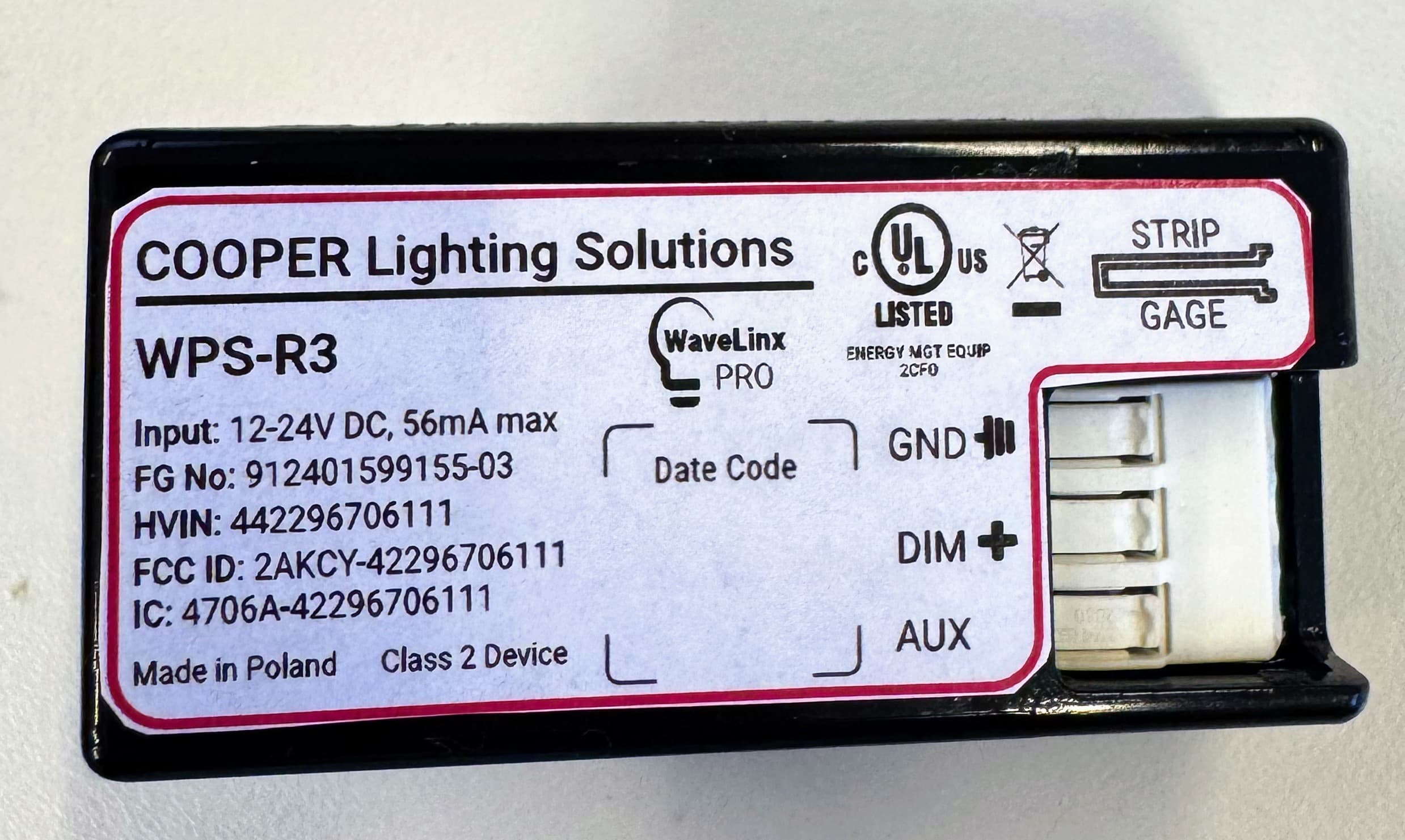
2AKCY-42296706111
Nov 17, 2025Lighting-control sensor module
Equipment Class
DTS - Digital Transmission System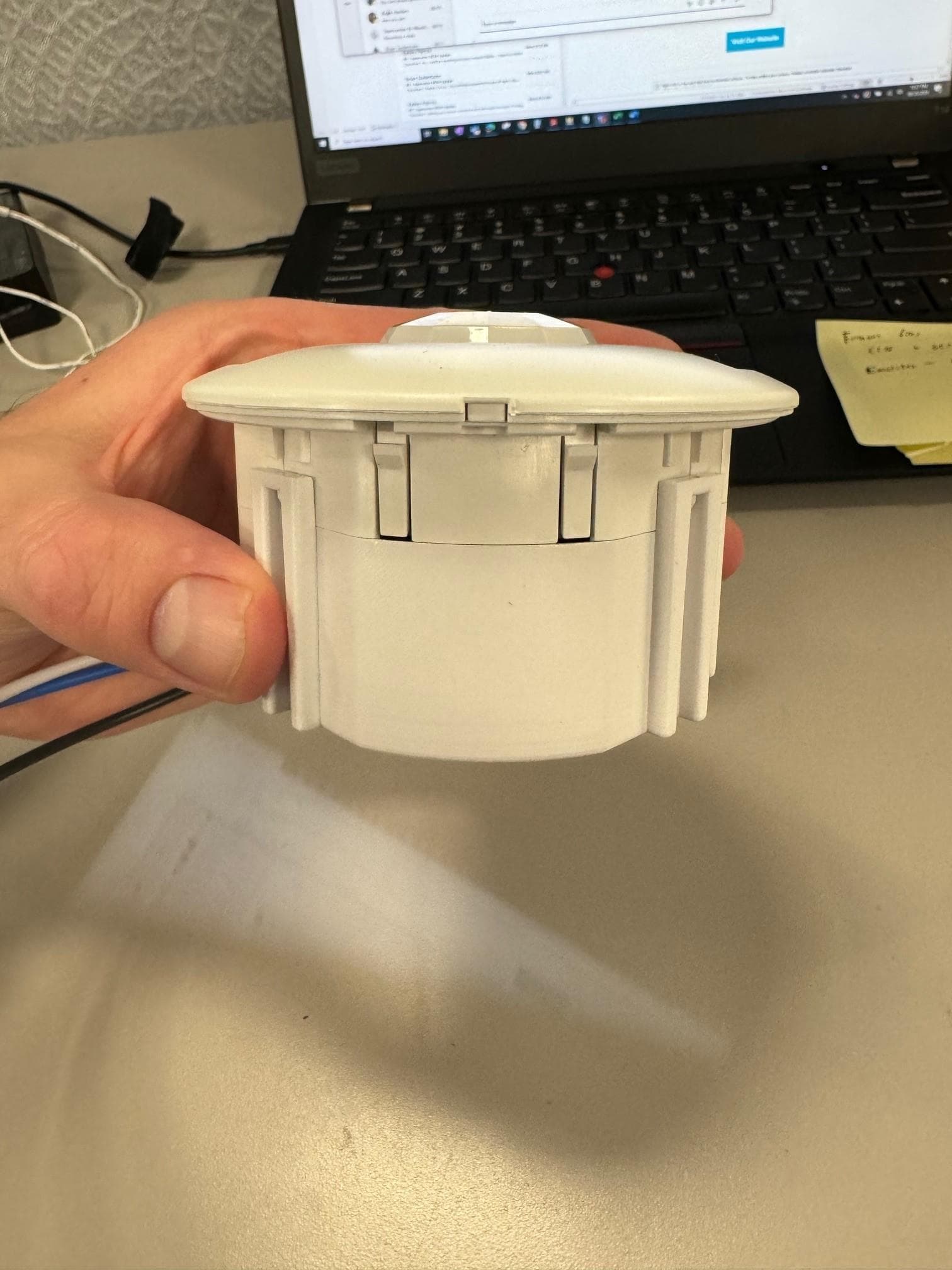
2AKCY-OCS-L-P-D
Aug 15, 2024Acoustic Ceiling Sensor
Equipment Class
DTS - Digital Transmission System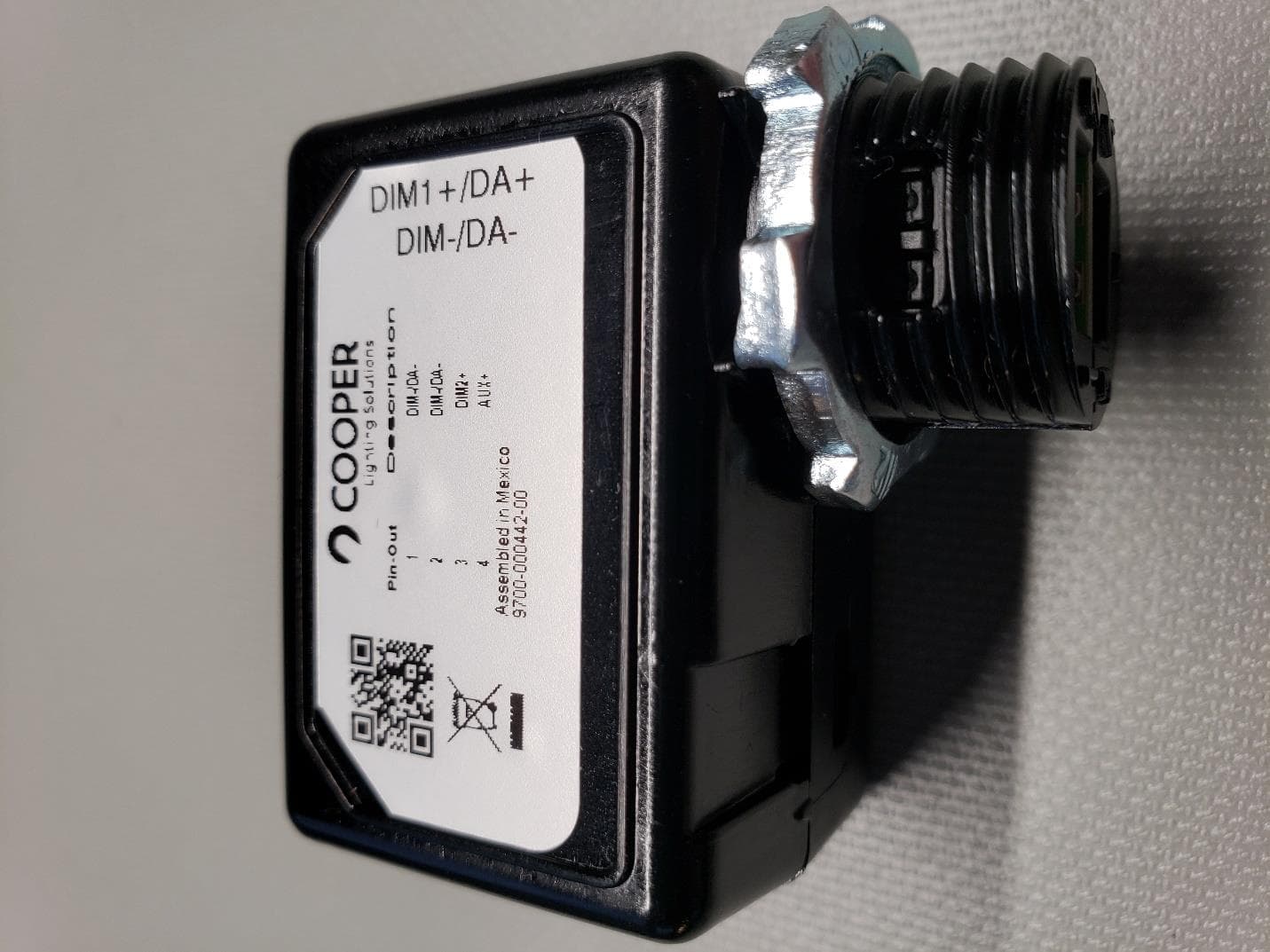
2AKCY-0028000021
Aug 04, 2022Wavelinx Pro Wireless Node
Equipment Class
DTS - Digital Transmission System