2AKCZ-0F8Wireless Network Security Appliance
SonicWall Inc.
Click to zoom
Application Details
- Equipment Class
- DTS - Digital Transmission System
- Date of Grant
- May 28, 2020
- Application Purpose
- Original Equipment
- Date of Application
- May 26, 2020
- Equipment Note
- Wireless Network Security Appliance
- Frequency Range
- 2412.00000000 - 2462.00000000
- Company
- SonicWall Inc.
- Country
- United States
Documents & Files
Document Text
Text extracted from the exhibit documents filed with the FCC. Open a document above to read the original.
Users Manual
• SonicWall SonicWave 231c 1 Safety and Regulatory Information TZ570W Safety and Regulatory Reference Guide Regulatory Model Number APL62-0F8 This document contains safety and regulatory information for the SonicWall TZ570W. The TZ570W is a wireless network security appliance with an internal wireless radio that can provide wireless access on either 5GHz or 2.4GHz and supports the 802.11 ac/n/g/a/b standards. Topics: SonicWall SonicWave 231c 2 Safety and Regulatory Information Safety Information for Installation and Operation • Installation Requirements • RF Safety Distance • Cable Connections • Power Supply Information • Restricted Environments • Radio Approvals • Radio or Television Interference • Wireless Interoperability NOTE: Additional regulatory notifications and information for this product can be found online at: https://www.sonicwall.com/support/technical‐documentation TZ570W complies with FCC U‐NII New Rules. Regulatory Model/Type Product Name Installation Requirements WARNING: The following conditions are required for proper installation: APL62-0F8 TZ570W SonicWall SonicWave 231c 3 Safety and Regulatory Information 1 Mount in a location away from direct sunlight and sources of heat. A maximum ambient temperature of 104º F (40º C) is recommended. 2 Route cables away from power lines, fluorescent lighting fixtures, and sources of noise such as radios, transmitters, and broadband amplifiers. 3 The included power cord(s) are approved for use only in specific countries or regions. Before using a power cord, verify that it is rated and approved for use in your location. 4 Ensure that no water or excessive moisture can enter the unit. 5 Allow unrestricted airflow around the unit. A minimum of 1 inch (25.44mm) clearance is recommended. 6 Consideration must be given to the connection of the equipment to the supply circuit. Appropriate consideration of equipment nameplate ratings must be used when addressing this concern. Do not overload the circuit. 7 Reliable grounding of power supply must be maintained. Particular attention must be given to power supply connections other than direct connections to the branch circuits, such as power strips. 8 When using a Fiber Optic Small-Form Pluggable (SFP) module, ensure it is IEC 60825 certified and a Class 1 Laser Product. 9 This equipment is not intended for use at workplaces with visual display units, in accordance with §2 of the German ordinance for workplaces with visual display units. To avoid incommoding reflections at visual display workplaces, this device must not be placed in the direct field of view. RF Safety Distance The antennas used for this transmitter must be installed to provide a separation distance of at least 20 cm from all persons and must not be co‐located or operating in conjunction with another antenna or transmitter Cable Connections All Ethernet and RS232 (Console) cables are designed for intra‐building connection to other equipment. Do not connect these ports directly to communication wiring or other wiring that exits the building where the appliance is located. Lithium Battery Warning The Lithium Battery used in the SonicWall security appliance may not be replaced by the user. Return the SonicWall security appliance to a SonicWall-authorized service center for replacement with the same or equivalent type recommended by the manufacturer. If, for any reason, the battery or SonicWall security appliance must be disposed of, do so following the battery manufacturer's instructions. Power Supply Information If the power supply is missing from your SonicWall product package, contact SonicWall Technical Support at https://support.sonicwall.com/contact-support for a replacement. This product should only be used with a UL listed power supply marked “I.T.E. LPS,” with an output rated 12V DC, minimum 5.0 A, Tma: minimum 40 degrees C. SonicWall SonicWave 231c 4 Safety and Regulatory Information Restricted Environments The SonicWall wireless device, like other radio devices, emits radio frequency electromagnetic energy. The SonicWall wireless device operates within the guidelines found in radio frequency safety and recommendations. These standards and recommendations reflect the consensus of the scientific community and result from deliberations of panels and committees of scientists who continually review and interpret the extensive research literature. In some situations or environments, the use of the SonicWall wireless device may be restricted by the proprietor of the building or responsible representatives of the applicable organization. Examples of such situations include the following: • Using the SonicWall wireless device equipment on board airplanes, or • Using the SonicWall wireless device equipment in any other environment where the risk of interference with other devices or services is perceived or identified as being harmful. If you are uncertain of the policy that applies to the use of wireless devices in a specific organization or environment (an airport, for example), you are encouraged to ask for authorization to use the SonicWall wireless device before you turn it on. WARNING: Explosive Device Proximity Warning: Do not operate a portable transmitter (such as a wireless network device) near unshielded blasting caps or in an explosive environment unless the device has been modified to be qualified for such use. WARNING: Use on Aircraft Caution: Regulations of the FCC and FAA prohibit airborne operation of radio-frequency wireless devices because their signals could interfere with critical aircraft instruments. Radio Approvals It is important to ensure that you only use your radio device in countries where the device is approved for use. To determine whether you are allowed to use your wireless network device in a specific country, check to see if the radio type number that is printed on the identification label of your device or listed on the radio approval list posted on the general SonicWall support site at: https…
Text truncated - open the document above for the full version.
Users Manual
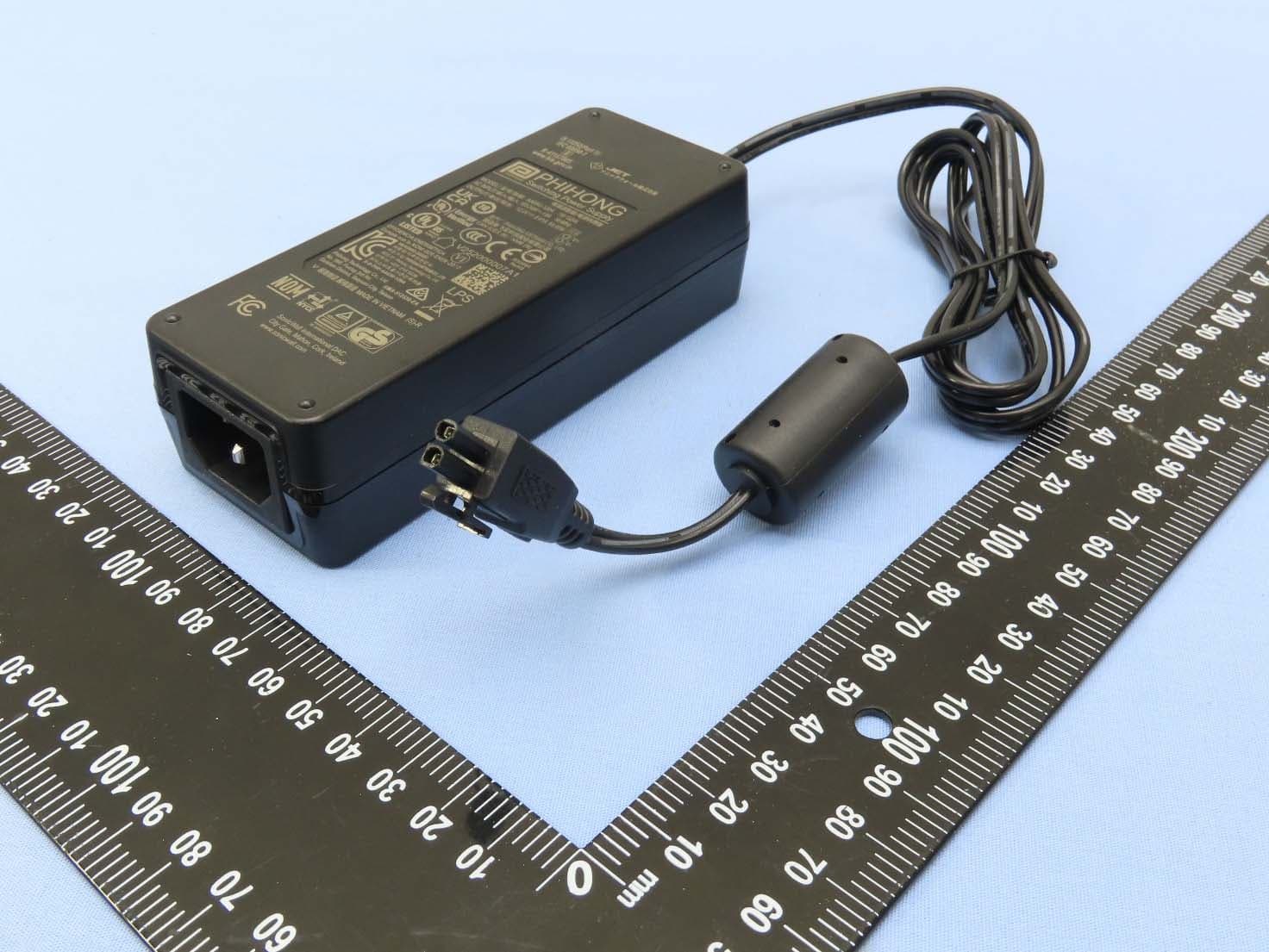
1 TZ570 / TZ570W Front The Service LED flashes yellow when any of the following events occur: ActiveX Blocked, ActiveX or Java archive access denied, Cookie Removed, Fragmented Packet Blocked, IP Spoof Detected, Java Blocked, Land Attack Dropped, Newsgroup Accessed, Press and hold until test LED starts blinking to set the appliance into Safe Mode For WAN access Newsgroup Blocked, Ping of Death Blocked, Proxy Access Blocked, Smurf Amplification Dropped, TCP SYN/FIN Packet Dropped, TCP Xmas Tree Packet Dropped, Unauthorized TCP Packet Denied, Unauthorized UDP Packet Denied, Unauthorized ICMP Packet Denied, Website Accessed, Website Blocked. 2 Check Package Contents Verify that your package has the following contents: •SonicWall TZ570 or TZ570 Wireless appliance •Antennas (2) (TZ570 Wireless appliance only) •Ethernet cable •Power adapter •Power cord •Quick Start Guide •Safety Environmental Regulatory Information (SERI) NOTE: The included power cord is approved for use only in specific countries or regions. Before using a power cord, verify that it is rated and approved for use in your location. 3 Deploy Using Zero-Touch Your SonicWall appliance is Zero-Touch enabled. Zero-Touch makes it easy to register your unit and add it to Capture Security Center for management and reporting in 3 simple steps. For information about using Zero-Touch, see the Zero-Touch Deployment Guide on the Support portal. After completing the Zero-Touch deployment process, you can skip to Mounting the TZ Appliance in this guide. For non Zero-Touch deployments, continue with the next section. 4 Connect Interfaces and Power On •Connect the WAN interface (X1) to your Internet connection using a standard Ethernet cable. •Connect the LAN interface (X0) to your computer using a standard Ethernet cable. Internet X1 (wan) X0 (lan) •Connect the antennas to the appliance (TZ570 Wireless appliance only). •Connect the power adapter to the appliance and to the power cable. Plug the power cable into an appropriate outlet (100-240 volts AC). •The TZ appliance powers on, and the Test LED lights up during the boot sequence and then turns off when boot sequence is complete. 120V AC (U.S.) CAUTION: Only use the included power adapter with this appliance. Do not use a power adapter that is damaged or from another appliance. 5 Run the Setup Wizard •Navigate to https://192.168.168.168 in your Web browser. •Click on the link in “To launch the SonicWall Setup Guide, click here.” •The SonicOS Startup Guide opens. •Click NEXT and follow the prompts in the Startup Guide. TIP: Your computer should be using DHCP IP addressing. •In the Credentials screen, enter a new administrator password. Click NEXT. •The automatically assigned DHCP IP settings are displayed in the IP Configuration screen. Click NEXT. •In the Setup Complete screen, review the settings and then click DONE. The SonicOS login screen displays. NOTE: The default administrator credentials are Username: admin Password: password NOTE: For manual configuration, refer to the latest SonicOS Quick Configuration administration documentation. SonicWall ® TZ570 and TZ570 Wireless Quick Start Guide Regulatory Model Number / Product: APL262-0F7 / TZ570 APL62-0F8 / TZ570W 6 Register Product Registration is an important part of the setup process and is necessary in order to receive the benefits of SonicWall security services, firmware updates, and technical support. To register the appliance from SonicOS: •Continue from the Setup Guide or point your browser to the appliance LAN IP address (default https://192.168.168.168) and log in using the administrator credentials. •Click Register in the top banner or on the MONITOR | Current Status | System Status page under Security Services. •Log in using your MySonicWall account name and password. If you do not have a MySonicWall account, go to http://www.mysonicwall.com to create an account. •MySonicWall directly obtains the necessary information from the appliance. When finished, you will see a message that registrat ion has been completed. Click Continue. TIP: Registering the appliance from SonicOS requires that DNS Server settings are configured on the WAN (X1) interface. 7 Configuring Wireless LAN Settings •Log in to your TZ appliance and click QUICK CONFIGURATION at the top of the screen. •Select the radio button for the Wireless Guide wizard. •Click Next and follow the prompts in the Wireless Guide wizard. Fo r more information and complete procedures, refer to the latest SonicOS Quick Configuration Guide. You are asked to select a country code when using the Wireless Guide or when yo u initially navigat e to the Wireless > Settings p age. Be sure to select the country code for the country in which the appliance will be deployed, even if you are not currently in that country. 8 Getting the Latest Firmware •In a Web browser, navigate to http://www.mysonicwall.com. •Navigate to Resources & Support > My Downloads and select TZ570 or TZ350W Firmware from the Product Type drop-down menu. IMPORTANT: When sold into USA list will be restricted to USA. When sold into Canada valid selection will be restricted to Canada. •Click the link for the firmware you want and save the file to a location on your computer. •On the TZ appliance, navigate to the MANAGE | Updates > Firmware & Backups > Upload Firmware page. Click the Upload New Firmware button. •Click the Choose File button to select the firmware you just downloaded, then click Upload. •Click the Boot icon for your new firmware. 9 Mounting the TZ Appliance For optional wall mounting, you need: •Screwdriver •Drill with appropriate size bit •For mounting on drywall: •Two #6 pan-head screws, 1 inch long (7mm diameter head, 25mm long) WARNING: Do not mount the appliance on the ceiling, it is not designed for secure ceiling mounting. •Two wall anchors •For mounting on solid wood or metal: •Two #6 pan-head wood or machine screws, 1 inch long (7mm diameter head, 25mm long) To mount the appliance on the wall: 1 Dril…
Text truncated - open the document above for the full version.
Attestation Statements
FCC ID: 2AKCZ-0F8 Operational Description This device is a Wireless Network Security Appliance, which operates in 2.4GHz band & 5.0GHz band; the maximum data rate could be up to 300Mbps which OFDM technique. If the signal to noise radio is too poor which could not support 300 Mbps, the 11Mbps data rate with DSSS technique will be applied. The device characteristics see below for reference. Model Name APL62-0F8 Power Supply 12Vdc from Adapter Modulation Technology DSSS, OFDM Operating Frequency 2.4GHz: 2412 ~ 2462MHz 5.0GHz: 5180 ~ 5240MHz 5745 ~ 5825MHz (channel list please refer to as below) Transmitter Chip QCA99XX with 48MHz crystal Antenna Type Dipole Antenna Connector RP-SMA 2.4GHz: 11 channels are provided for 802.11b, 802.11g and 802.11n (HT20): Channel Frequency Channel Frequency 1 2412MHz 7 2442MHz 2 2417MHz 8 2447MHz 3 2422MHz 9 2452MHz 4 2427MHz 10 2457MHz 5 2432MHz 11 2462MHz 6 2437MHz 7 channels are provided for 802.11n (HT40): Channel Frequency Channel Frequency 3 2422MHz 7 2442MHz 4 2427MHz 8 2447MHz 5 2432MHz 9 2452MHz 6 2437MHz FCC ID: 2AKCZ-0F8 5.0GHz: FOR 5180 ~ 5240MHz 4 channels are provided for 802.11a, 802.11n (HT20), 802.11ac (VHT20): Channel Frequency Channel Frequency 36 5180 MHz 44 5220 MHz 40 5200 MHz 48 5240 MHz 2 channels are provided for 802.11n (HT40), 802.11ac (VHT40): Channel Frequency Channel Frequency 38 5190 MHz 46 5230 MHz 1 channel is provided for 802.11ac (VHT80): Channel Frequency 42 5210MHz FOR 5745 ~ 5825MHz: 5 channels are provided for 802.11a, 802.11n (HT20), 802.11ac (VHT20): Channel Frequency Channel Frequency 149 5745MHz 161 5805MHz 153 5765MHz 165 5825MHz 157 5785MHz 2 channels are provided for 802.11n (HT40), 802.11ac (VHT40): Channel Frequency Channel Frequency 151 5755MHz 159 5795MHz 1 channel is provided for 802.11ac (VHT80): Channel Frequency 155 5775MHz The other instruction, please have a look at the user’s manual. FCC ID: 2AKCZ-0F8 FCC 15.407(c) states: The device shall automatically discontinue transmission in case of either absence of information to transmit or operational failure. These provisions are not intended to preclude the transmission of control or signaling information or the use of repetitive codes used by certain digital technologies to complete frame or burst intervals. Applicants shall include in their application for equipment authorization a description of how this requirement is met” Data transmission is always initiated by software, which is then pass down through the MAC, through the digital and analog baseband, and finally to the RF chip. Several special packets (ACKs, CTS, PSPoll, etc...) are initiated by the MAC. There are the only ways the digital baseband portion will turn on the RF transmitter, which it then turns off at the end of the packet. Therefore, the transmitter will be on only while one of the aforementioned packets are being transmitted.
Cover Letter(s)
1033 McCarthy Boulevard, Milpitas, California 95035 USA Office +1-888-557-6642 Date: 2020-04-23 FCC ID: 2AKCZ-0F8 To the attention of Federal Communications Commission Authorization and Evaluation Division Permanent Confidentiality Request Pursuant to Sections 0.457 and 0.459 of the Commission’s Rules, the Applicant hereby requests confidential treatment of information accompanying this Application as outlined below: Schematics Block Diagram Operational Description Software Operational Description The above materials contain trade secrets and proprietary information not customarily released to the public. The public disclosure of these matters might be harmful to the Applicant and provide unjustified benefits to its competitors. The Applicant understands that pursuant to Rule 0.457, disclosure of this Application and all accompanying documentation will not be made before the date of the Grant for this application. Sincerely yours, Sincerely yours, ----------------------------------- Rick Linford / Regulatory Engineer Telephone Number: +1408.962.8798 Fax Number: +1 408.962.8798 E-mail Address: [email protected]
Cover Letter(s)
1033 McCarthy Boulevard, Milpitas, California 95035 USA Office +1-888-557-6642 Date: 2020-04-23 FCC ID: 2AKCZ-0F8 A U T H O R I Z A T I O N L E T T E R To Whom It May Concern: SonicWall Inc. hereby authorizes Andrea Hsia / Supervisor of Bureau Veritas Consumer Products Services (H.K.) Ltd., Taoyuan Branch (“BV CPS Taoyuan”), to act on its behalf in all matters relating to the Federal Communication Commission (“FCC”) application for SonicWall Regulatory Model APL62-0F8 Wireless Network Security Appliance authorization in connection with the FCC ID listed above, including signing of all documents relating to these matters. Any and all acts carried out by Andrea Hsia / Supervisor of BV CPS Taoyuan on SonicWall Inc.’s behalf, within the scope of the powers granted herein, shall have the same effect as acts of its own. If you have any questions regarding the authorization, please don’t hesitate to contact us. Sincerely yours, ----------------------------------- Rick Linford / Regulatory Engineer Telephone Number: +1408.962.8798 Fax Number: +1 408.962.8798 E-mail Address: [email protected]
External Photos
Reference No.: 191209C26-1 Page No. 1 / 11 CONSTRUCTION PHOTOS OF EUT Reference No.: 191209C26-1 Page No. 2 / 11 Reference No.: 191209C26-1 Page No. 3 / 11 Reference No.: 191209C26-1 Page No. 4 / 11 Reference No.: 191209C26-1 Page No. 5 / 11 Reference No.: 191209C26-1 Page No. 6 / 11 Reference No.: 191209C26-1 Page No. 7 / 11 Reference No.: 191209C26-1 Page No. 8 / 11 Reference No.: 191209C26-1 Page No. 9 / 11 Reference No.: 191209C26-1 Page No. 10 / 11 Reference No.: 191209C26-1 Page No. 11 / 11
ID Label/Location Info
The label will be permanently affixed and readily visible. Label location
ID Label/Location Info
201 1504XX R CCAJXXLPXXXXX CMIIT ID:XXXVVXXX “Este equipamento opera em caráter secundário, isto é, não tem direito a proteção contra interferência prejudicial, mesmo de estações do mesmo tipo, e não pode causar interferência a sistemas operando em caráter primário.” 5C5C5C5C5C5C C5C5-C5C5 FCC ID: 2AKCZ-0F8 IC:22137-0F8 網路安全設備 Made in Taiwan/台灣製造 台湾制造 C-17XXX SONICWALL SONICWALL Serial Number: Authentication Code: Model/型號:APL62-0F8 V/額定電壓:12 V A/額定電流:5 A CAN ICES-3 (B)/NMB-3(B) ASSY:101-500XXX-50 Rev. X LBL PN:341-000047-XX A SonicWall International Ltd. City Gate Park, Mahon,Cork,Ireland www.sonicwall.com This device complies with Par t 15 of the FCC Rules. Operation is subject to the following two conditions: 1) This device may not cause harmful interfer ence, and 2) this device must accept any interfer ence received, including interfer ence that may cause undesired operation. 10 产品型号: TZ570W D3B337 RoHS 网络安全设备 TZ570W 额定电压: 12 V 额定电流: 5 A XXXXX-XX-XXXXX 電波法により5GHz は屋内使用に限ります � ���� � �� � ���� ��� � �� R-R-SWL-0F8 [email protected] 制造商: SonicWall Inc.
Internal Photos
Reference No.: 191209C26-2 Page No. 1 / 9 CONSTRUCTION PHOTOS OF EUT Reference No.: 191209C26-2 Page No. 2 / 9 Reference No.: 191209C26-2 Page No. 3 / 9 Reference No.: 191209C26-2 Page No. 4 / 9 Reference No.: 191209C26-2 Page No. 5 / 9 Reference No.: 191209C26-2 Page No. 6 / 9 Reference No.: 191209C26-2 Page No. 7 / 9 Reference No.: 191209C26-2 Page No. 8 / 9 Reference No.: 191209C26-2 Page No. 9 / 9
RF Exposure Info
Report No.: SA191209C26 Page No. 1 / 6 Report Format Version: 6.1.1 RF Exposure Report Report No.: SA191209C26 FCC ID: 2AKCZ-0F8 Test Model: APL62-0F8 Received Date: Dec. 09, 2019 Test Date: Dec. 26, 2019 ~ Apr. 20, 2020 Issued Date: Apr. 22, 2020 Applicant: SonicWall Inc. Address: 1033 McCarthy Blvd., Milpitas, CA 95035, USA Issued By: Bureau Veritas Consumer Products Services (H.K.) Ltd., Taoyuan Branch Lin Kou Laboratories Lab Address: No. 47-2, 14th Ling, Chia Pau Vil., Lin Kou Dist., New Taipei City, Taiwan Test Location: No. 19, Hwa Ya 2nd Rd., Wen Hwa Vil., Kwei Shan Dist., Taoyuan City 33383, Taiwan FCC Registration / Designation Number: 788550 / TW0003 This report is for your exclusive use. Any copying or replication of this report to or for any other person or entity, or use of our name or trademark, is permitted only with our prior written permission. This report sets forth our findings solely with respect to the test samples identified herein. The results set forth in this report are not indicative or representative of the quality or characteristics of the lot from which a test sample was taken or any similar or identical product unless specifically and expressly noted. Our report includes all of the tests requested by you and the results thereof based upon the information that you provided to us. You have 60 days from date of issuance of this report to notify us of any material error or omission caused by our negligence, provided, however, that such notice shall be in writing and shall specifically address the issue you wish to raise. A failure to raise such issue within the prescribed time shall constitute your unqualified acceptance of the completeness of this report, the tests conducted and the correctness of the report contents. Unless specific mention, the uncertainty of measurement has been explicitly taken into account to declare the compliance or non-compliance to the specification. The report must not be used by the client to claim product certification, approval, or endorsement by TAF or any government agencies. Report No.: SA191209C26 Page No. 2 / 6 Report Format Version: 6.1.1 Table of Contents Release Control Record .................................................................................................................................. 3 1 Certificate of Conformity ...................................................................................................................... 4 2 RF Exposure .......................................................................................................................................... 5 2.1 Limits for Maximum Permissible Exposure (MPE) .............................................................................. 5 2.2 MPE Calculation Formula ................................................................................................................... 5 2.3 Classification ....................................................................................................................................... 5 3 Calculation Result of Maximum Conducted Power ........................................................................... 6 Report No.: SA191209C26 Page No. 3 / 6 Report Format Version: 6.1.1 Release Control Record Issue No. Description Date Issued SA191209C26 Original release. Apr. 22, 2020 Report No.: SA191209C26 Page No. 4 / 6 Report Format Version: 6.1.1 1 Certificate of Conformity Product: Wireless Network Security Appliance Brand: SONICWALL Test Model: APL62-0F8 Sample Status: Engineering sample Applicant: SonicWall Inc. Test Date: Dec. 26, 2019 ~ Apr. 20, 2020 Standards: FCC Part 2 (Section 2.1091 References Test Guidance: KDB 447498 D01 General RF Exposure Guidance v06 IEEE C95.3 -2002 The above equipment has been tested by Bureau Veritas Consumer Products Services (H.K.) Ltd., Taoyuan Branch, and found compliance with the requirement of the above standards. The test record, data evaluation & Equipment Under Test (EUT) configurations represented herein are true and accurate accounts of the measurements of the sample’s RF characteristics under the conditions specified in this report. Prepared by : , Date:Apr. 22, 2020 Polly Chien / Specialist Approved by : , Date:Apr. 22, 2020 Bruce Chen / Senior Project Engineer Report No.: SA191209C26 Page No. 5 / 6 Report Format Version: 6.1.1 2 RF Exposure 2.1 Limits for Maximum Permissible Exposure (MPE) Frequency Range (MHz) Electric Field Strength (V/m) Magnetic Field Strength (A/m) Power Density (mW/cm 2 ) Average Time (minutes) Limits For General Population / Uncontrolled Exposure 0.3-1.34 614 1.63 (100)* 30 1.34-30 824/f 2.19/f (180/f 2 )* 30 30-300 27.5 0.073 0.2 30 300-1500 ... ... f/1500 30 1500-100,000 ... ... 1.0 30 f = Frequency in MHz; *Plane-wave equivalent power density 2.2 MPE Calculation Formula Pd = (Pout*G) / (4*pi*r 2 ) where Pd = power density in mW/cm 2 Pout = output power to antenna in mW G = gain of antenna in linear scale Pi = 3.1416 R = distance between observation point and center of the radiator in cm 2.3 Classification The antenna of this product, under normal use condition, is at least 20m away from the body of the user. So, this device is classified as Mobile Device. Report No.: SA191209C26 Page No. 6 / 6 Report Format Version: 6.1.1 3 Calculation Result of Maximum Conducted Power Frequency Band (MHz) Max Average Power (dBm) Antenna Gain (dBi) Distance (cm) Power Density (mW/cm 2 ) Limit (mW/cm 2 ) CDD mode WLAN 2412~2462 26.62 6.20 20 0.381 1 WLAN 5180~5240 24.96 8.86 20 0.479 1 WLAN 5745~5825 24.38 8.86 20 0.419 1 Beamforming mode WLAN 2412~2462 18.75 6.20 20 0.062 1 WLAN 5180~5240 21.92 8.86 20 0.238 1 WLAN 5745~5825 21.37 8.86 20 0.210 1 Note: Determining compliance based on the results of the compliance measurement, not taking into account measurement instrumentation uncertainty. * WLAN 2.4GHz & WLAN 5GHz technology cannot transmit at same time. 2.4GHz: Directional gain = 3.19dBi +10log(2) = 6.20dBi 5.0GHz: Directi…
Text truncated - open the document above for the full version.
Test Report
Report No.: RF191209C26 Page No. 1 / 60 Report Format Version: 6.1.1 FCC Test Report Report No.: RF191209C26 FCC ID: 2AKCZ-0F8 Test Model: APL62-0F8 Received Date: Dec. 09, 2019 Test Date: Dec. 26, 2019 ~ Feb. 12, 2020 Issued Date: Feb. 17, 2020 Applicant: SonicWall Inc. Address: 1033 McCarthy Blvd., Milpitas, CA 95035, USA Issued By: Bureau Veritas Consumer Products Services (H.K.) Ltd., Taoyuan Branch Lin Kou Laboratories Lab Address: No. 47-2, 14th Ling, Chia Pau Vil., Lin Kou Dist., New Taipei City, Taiwan Test Location: No. 19, Hwa Ya 2nd Rd., Wen Hwa Vil., Kwei Shan Dist., Taoyuan City 33383, Taiwan FCC Registration / Designation Number: 788550 / TW0003 This report is for your exclusive use. Any copying or replication of this report to or for any other person or entity, or use of our name or trademark, is permitted only with our prior written permission. This report sets forth our findings solely with respect to the test samples identified herein. The results set forth in this report are not indicative or representative of the quality or characteristics of the lot from which a test sample was taken or any similar or identical product unless specifically and expressly noted. Our report includes all of the tests requested by you and the results thereof based upon the information that you provided to us. You have 60 days from date of issuance of this report to notify us of any material error or omission caused by our negligence, provided, however, that such notice shall be in writing and shall specifically address the issue you wish to raise. A failure to raise such issue within the prescribed time shall constitute your unqualified acceptance of the completeness of this report, the tests conducted and the correctness of the report contents. Unless specific mention, the uncertainty of measurement has been explicitly taken into account to declare the compliance or non-compliance to the specification. This report should not be used by the client to claim product certification, approval, or endorsement by TAF or any government agencies. Report No.: RF191209C26 Page No. 2 / 60 Report Format Version: 6.1.1 Table of Contents Release Control Record .................................................................................................................................. 4 1 Certificate of Conformity ...................................................................................................................... 5 2 Summary of Test Results ..................................................................................................................... 6 2.1 Measurement Uncertainty ................................................................................................................... 6 2.2 Modification Record ............................................................................................................................ 6 3 General Information .............................................................................................................................. 7 3.1 General Description of EUT ................................................................................................................ 7 3.2 Description of Test Modes ................................................................................................................... 9 3.2.1 Test Mode Applicability and Tested Channel Detail ........................................................................... 10 3.3 Duty Cycle of Test Signal .................................................................................................................. 12 3.4 Description of Support Units ............................................................................................................. 13 3.4.1 Configuration of System under Test .................................................................................................. 13 3.5 General Description of Applied Standards and References ............................................................. 14 4 Test Types and Results ...................................................................................................................... 15 4.1 Radiated Emission and Bandedge Measurement ............................................................................. 15 4.1.1 Limits of Radiated Emission and Bandedge Measurement .............................................................. 15 4.1.2 Test Instruments ................................................................................................................................ 16 4.1.3 Test Procedures ................................................................................................................................. 17 4.1.4 Deviation from Test Standard .................................…
Text truncated - open the document above for the full version.
Contact Information
Applicant
Rick Linford(Regulatory Engineer)
Test Firm
Bureau Veritas CPS(H.K.) Ltd., Taoyuan BranchLiu Ken
Technical Specifications
| # | Rule Parts | Frequency Range | Power Output |
|---|---|---|---|
| 1 | 15C | 2.41 GHz - 2.46 GHz | 459.00 mW |
Other Applications from SonicWall Inc.
2AKCZ-11E
Nov 24, 2025Wireless Network Security Appliance
Equipment Class
DTS - Digital Transmission System
2AKCZ-108
Aug 16, 2022Wireless Access Point
Equipment Class
NII - Unlicensed National Information Infrastructure TX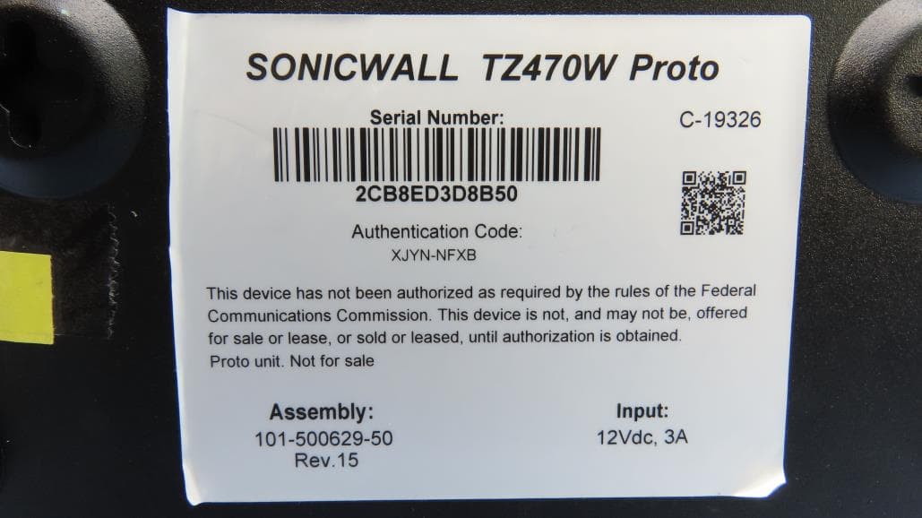
2AKCZ-101
Nov 12, 2020Wireless Network Security Appliance
Equipment Class
DTS - Digital Transmission System