2AKDT-MT1160BGraphic Drawing Tablet
XPPEN Technology CO.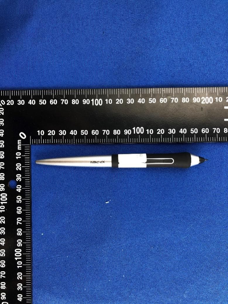
Click to zoom
Application Details
- Equipment Class
- DTS - Digital Transmission System
- Date of Grant
- Jun 29, 2021
- Application Purpose
- Original Equipment
- Date of Application
- Jun 29, 2021
- Equipment Note
- Graphic Drawing Tablet
- Frequency Range
- 2402.00000000 - 2480.00000000
- Company
- XPPEN Technology CO.
- Country
- United States
Documents & Files
Document Text
Text extracted from the exhibit documents filed with the FCC. Open a document above to read the original.
Users Manual
Quick Guide Deco Pro SW/MW www.xp-pen.com 1-2 3-4 English 5-6 繁体中文 7-8 9-10 11-12 13-14 15-16 17-18 한국어 Français 日本語 Español Deutsch Italiano 19-20 21-22 23-24 Русский язык Português Polski Contents Nederlands PAGE1PAGE2 英语 I. Overview 1. USB-C port 2. Trackpad/Touch 3. Indicator 1 In blue status: a. Flashing slowly: No Bluetooth connected b. Flashing quickly: Waiting for pairing with Bluetooth connection (Long press the shortcut key on the top left for 3 seconds) c. Always On: Successfully paired In red status: a. Flashing: Low battery (20%) b. Always On: Charging c. Off: Fully charged A purple color indicates that the red and the blue indicator are both On simultaneously 4. Roller 5. Shortcut keys 6. Active area 7. Indicator 2: Handwriting indicator: a. Flashing: The stylus is in the active area, but not touching the pen tablet b. Always On: The stylus is in contact with the active area c. Off: The stylus is outside the active area 8. Power key Deco Pro SW/MW Quick Guide Note: For the best performance of your device, we highly recommend you check and update driver regularly from XP-PEN website. III. Install the Driver 1. Make sure your pen tablet was connected to the computer. 2. Visit the XP-PEN website (www.xp-pen.com), choose Support section and click Download. Choose product model and download the latest driver according to your computer system. 3. Follow the prompts to finish the driver installation. Wired Connection Connect the pen tablet to your computer. The pen tablet will get started automatically. Wireless Connection A. Connection to the Bluetooth receiver Plug the Bluetooth receiver into the computer and then toggle the power key to turn the pen tablet on. B. Direct Bluetooth connection (Windows/Mac OS only) 1. Toggle the power key to turn the pen tablet on. Then long press the shortcut key on the top left for 3 seconds to enter Bluetooth pairing (with the blue indicator flashing quickly). 2. Turn on the Bluetooth on the computer, set up and add Bluetooth device, search for device name Deco Pro SW/MW and complete Bluetooth pairing by clicking the device name (with the blue indicator always on). 3. Toggle the power key to turn the pen tablet off after use. If you need any further assistance, please contact us: www.xp-pen.com service@xp-pen.com II. Getting Started 1 2 3 4 5 68 7 繁中 PAGE3PAGE4 一. 產品概覽 1. USB-C介面 2. 觸控板 3. 滾輪指示燈 藍色狀態 a. 慢閃: 無藍牙連接 b. 快閃: 藍牙等待配對(長按左上角快速鍵3秒進入配對狀態) c. 恒亮: 藍牙配對成功 紅色狀態 a. 閃爍: 電池低電量(20%以下) b. 恒亮: 電池充電中 c. 無燈號: 電池充滿電 紅/藍燈同亮時為紫色 4. 滾輪 5. 快速按鍵 6. 工作區域 7. 板面指示燈 手寫狀態顯示 a. 閃爍: 筆位於感應區域內但未觸碰到繪圖板 b. 恒亮: 筆觸碰到感應區域 c. 無燈號: 筆位於感應區域之外 8. 電源開關鍵 Deco Pro SW/MW快速指南 1. 有線連接 使用數據線將繪圖板連接至電腦,繪圖板自動開機 。 2. 無線連接 A. 藍牙接收器 將藍牙接收器插入電腦並開啟繪圖板 。 B. 藍牙無線直連(僅支援Windows/Mac OS) 1. 開啟繪圖板后長按左上角快速鍵3S,進入等待配對狀態(藍燈快閃)。 2. 打開電腦藍牙功能,添加藍牙設備,搜尋到Deco Pro SW/MW設備名 稱,點擊後完成藍牙配對(藍燈常亮)。 3. 撥動電源開關至OFF位置關機 。 二. 連接方式 1 2 3 4 5 68 7 溫馨提示: 為了使您的繪圖板/繪圖顯示器能夠展現最佳性能,建議您定期查看官網驅動更新 。 三. 下載安裝驅動程式 1. 確保您的繪圖板/繪圖顯示器與電腦處於連接狀態 。 2. 登陸XP-PEN 官網(www.xp-pen.com),進入“支持”頁面,點擊“下載”,依 照產品型號和您電腦作業系統,下載並安裝對應的驅動程式 。 3. 開啟驅動程式, 設定參數並測試產品功能 。 若您需要任何與產品相關的協助,請與我們聯系 service@xp-pen.com www.xp-pen.com PAGE5PAGE6 德语ok Hinweis: Um die optimale Leistung Ihres Geräts zu erzielen, empfehlen wir Ihnen, den Treiber regelmäßig auf der XP-PEN Website zu überprüfen und zu aktualisieren. Wenn Sie weitere Unterstützung benötigen, kontaktieren Sie uns bitte unter: III. Treiber installieren 1. Stellen Sie sicher, dass Ihr Tablet/Display an den Computer angeschlossen wurde. 2. Besuchen Sie die XP-PEN Website (www.xp-pen.de), wählen Sie den Bereich „Unterstützung“ und klicken Sie auf „Herunterladen“. Wählen Sie das gewünschte Produktmodell aus und laden Sie den neuesten Treiber herunter. 3. Befolgen Sie die Anweisungen, um den Treiber zu installieren. www.xp-pen.de servicede@xp-pen.com I. Übersicht 1. USB-C-Anschluss 2. Touchpad/Trackpad 3. Kontrolllampe 1 Im blauen Status: a. Blinkt langsam: Keine Bluetooth-Verbindung b. Blinkt schnell: Wartet auf Kopplung mit Bluetooth-Verbindung (die Schnellzugriffstaste oben links 3 Sekunden lang drücken) c. Kontinuierlich an: Erfolgreich gekoppelt Im roten Status: a. Blinkt: Niedrige Akkukapazität (20 %) b. Kontinuierlich an: Wird geladen c. Aus: Vollständig geladen Leuchtet die Kontrolllampe violett, sind der rote und blaue Status gleichzeitig aktiv 4. Dreh-Taste 5. Tastenkombinationen 6. Arbeitsbereich 7. Kontrolllampe 2 a. Blinkt: Der Stift befindet sich im aktiven Bereich, berührt aber das Tablet nicht b. Kontinuierlich an: Der Stift ist mit dem aktiven Bereich in Kontakt c. Aus: Der Stift befindet sich außerhalb des aktiven Bereichs 8. Power-Taste Kurzanleitung für die Deco SW/MW Kabelverbindung Schließen Sie das Grafiktablett über das USB-C Kabel an Ihren Computer an. Das Tablet wird automatisch gestartet. Drahtlose Verbindung A. Anschluss an den Bluetooth-Empfänger Schließen Sie den Bluetooth-Empfänger an den Computer an und schalten Sie dann das Tablet mit der Power-Taste ein. B. Direkte Bluetooth-Verbindung (nur Windows/Mac OS) 1. Schalten Sie das Tablet mit der Power-Taste ein. Drücken Sie dann 3 Sekunden lang die Schnellzugriffstaste oben links, um die Bluetooth-Kopplung zu starten (die blaue Anzeige blinkt schnell). 2. Schalten Sie Bluetooth am Computer ein, richten Sie ein Bluetooth-Gerät ein und fügen Sie es hinzu. Suchen Sie nach dem Gerätenamen Deco Pro SW/MW, dann klicken Sie auf den Gerätenamen (die blaue Anzeige ist kontinuierlich an). 3. Schalten Sie das Tablet nach der Verwendung mit der Power-Taste aus. II. Einrichten 1 2 3 4 5 68 7 西语ok PAGE7PAGE8 I. Descripción general 1. Puerto USB-C 2. Rueda de control/táctil 3. Indicador 1 Estado en azul: a. Si parpadea lentamente: el Bluetooth no está conectado b. Si parpadea rápidamente: está esperando el emparejamiento con la conexión Bluetooth (pulse prolongadamente la tecla de acceso directo en la parte superior izquierda durante 3 segundos) c. Siempre encendido: emparejado correctamente Estado en rojo: a. Si parpadea: batería baja (20 %) b. Siem…
Text truncated - open the document above for the full version.
Cover Letter(s)
XPPEN Technology CO. Agent Authorization Company: XPPEN Technology CO. Address: 4020 N Palm Street, Suite 206/207, Fullerton, California 92835 United States Product Name: Graphic Drawing Tablet Model Number(s): MT1160B, MT0960B, MT0960B-E, MT1060B, MT1060B-E, MT1160B-E, MT1400B, MT1400B-E, MT1600B, MT1600B-E, MT0961B, MT0961B- E, MT1061B, MT1061B-E, MT1161B, MT1161B-E, MT1401B, MT1401B-E, MT1601B, MT1601B-E Product Description: Graphic Drawing Tablet We authorize MiCOM Labs Inc., 575 Boulder Court, Pleasanton, California 94566, USA, to act on our behalf on all matters concerning the certification of above named equipment. We declare that MiCOM Labs Inc. is allowed to forward all information related to the approval and certification of equipment to the regulatory agencies as required and to discuss any issues concerning the approval application. Any and all acts carried out by MiCOM Labs on our behalf shall have the same effect as acts of our own. Signature: Date: 2021-06-24 Name: Tiger Li Title: general manager Company: XPPEN Technology CO.
Cover Letter(s)
(XPPEN Technology CO.) Declaration Of Identity Hereby we: XPPEN Technology CO. (name of Manufacturer) Basic Model Number: MT1160B Basic Brand Name: XP-PEN Basic Product Name: Graphic Drawing Tablet Declare the Circuit, PCB Layout, Electrical Parts and Outlook of the following product(s) are identical to the basic model: ☐New/☒ Additional Model Number(s): MT0960B, MT0960B-E, MT1060B, MT1060B-E, MT1160B-E, MT1400B, MT1400B-E, MT1600B, MT1600B-E, MT0961B, MT0961B-E, MT1061B, MT1061B-E, MT1161B, MT1161B-E, MT1401B, MT1401B-E, MT1601B, MT1601B-E ☐New/☐Additional Brand Name(s): ☐New/☐Additional Product Name(s): Except the following(s): Remarks: The EUT has two sizes, and in this report we do MT1160B & MTO960B. There is no difference between software and hardware of RF, except screen size. Based on these differences, we tested both sizes for Conducted Emission, Radiated Spurious Emission & Band Edge(Restricted-band band-edge). Signature: Print Name: Tiger Li Date: 2021.06.24
External Photos
AnnexNo.:BL-SZ2140519-AW 1 / 7 EUTEXTERNALPHOTOS MT1160B FRONTVIEWOFEUT REARVIEWOFEUT AnnexNo.:BL-SZ2140519-AW 2 / 7 LEFTSIDEVIEWOFEUT RIGHTSIDEOFEUT AnnexNo.:BL-SZ2140519-AW 3 / 7 TOPVIEWOFEUT BOTTOMVIEWOFEUT AnnexNo.:BL-SZ2140519-AW 4 / 7 MT0960B FRONTVIEWOFEUT REARVIEWOFEUT AnnexNo.:BL-SZ2140519-AW 5 / 7 LEFTSIDEVIEWOFEUT RIGHTSIDEOFEUT AnnexNo.:BL-SZ2140519-AW 6 / 7 TOPVIEWOFEUT BOTTOMVIEWOFEUT . AnnexNo.:BL-SZ2140519-AW 7 / 7 Accessory-USBCable Accessory-Paintingpen
ID Label/Location Info
Label Location
Internal Photos
AnnexNo.:BL-SZ2140519-AI 1 / 6 EUTINTERNALPHOTOS MT1160B EUTUNCOVERVIEW EUTUNCOVERVIEW PIFAAntenna AnnexNo.:BL-SZ2140519-AI 2 / 6 MAINBOARDTOPVIEW MAINBOARDREARVIEW RFChip AnnexNo.:BL-SZ2140519-AI 3 / 6 BatteryPhoto(FRONT) BatteryPhoto(REAR) AnnexNo.:BL-SZ2140519-AI 4 / 6 MT0960B EUTUNCOVERVIEW EUTUNCOVERVIEW PIFAAntenna AnnexNo.:BL-SZ2140519-AI 5 / 6 MAINBOARDTOPVIEW MAINBOARDREARVIEW RFChip AnnexNo.:BL-SZ2140519-AI 6 / 6 BatteryPhoto(FRONT) BatteryPhoto(REAR)
Test Report
Report No.: BL-SZ2140519-601 2 / 83 Revision History Version Issue Date Revisions Content Rev. 01 Jun. 30, 2021 Initial Issue TABLE OF CONTENTS 1 ADMINISTRATIVE DATA (GENERAL INFORMATION) ........................................................................ 5 1.1 Identification of the Testing Laboratory ..................................................................................... 5 1.2 Identification of the Responsible Testing Location .................................................................... 5 1.3 Laboratory Condition ................................................................................................................ 5 1.4 Announce ................................................................................................................................. 5 2 PRODUCT INFORMATION ................................................................................................................... 6 2.1 Applicant Information ................................................................................................................ 6 2.2 Manufacturer Information .......................................................................................................... 6 2.3 Factory Information ................................................................................................................... 6 2.4 General Description for Equipment under Test (EUT) ............................................................... 6 2.5 Technical Information ............................................................................................................... 7 2.6 Additional Instructions .............................................................................................................. 8 3 SUMMARY OF TEST RESULTS ........................................................................................................... 9 3.1 Test Standards ......................................................................................................................... 9 3.2 Verdict .................................................................................................................................... 10 4 GENERAL TEST CONFIGURATIONS ................................................................................................ 11 4.1 Test Environments .................................................................................................................. 11 4.2 Test Equipment List ................................................................................................................ 11 4.3 Measurement Uncertainty ....................................................................................................... 11 4.4 Description of Test Setup ....................................................................................................... 12 4.4.1 For Antenna Port Test ............................................................................................................ 12 4.4.2 For AC Power Supply Port Test .............................................................................................. 12 4.4.3 For Radiated Test (Below 30 MHz) ......................................................................................... 13 4.4.4 For Radiated Test (30 MHz-1 GHz) ........................................................................................ 13 4.4.5 For Radiated Test (Above 1 GHz) .......................................................................................... 14 4.5 Measurement Results Explanation Example ........................................................................... 15 4.5.1 For conducted test items: ....................................................................................................... 15 Report No.: BL-SZ2140519-601 3 / 83 4.5.2 For radiated band edges and spurious emission test: ............................................................. 15 5 TEST ITEMS ....................................................................................................................................... 16 5.1 Antenna Requirements ........................................................................................................... 16 5.1.1 Relevant Standards ................................................................................................................ 16 5.1.2 Antenna Anti-Replacement Construction ................................................................................ 16 5.1.3 Antenna Gain ......................................................................................................................... 16 5.2 Output Power ......................................................................................................................... 17 5.2.1 Test Limit ................................................................................................................................ 17 5.2.2 Test Setup .............................................................................................................................. 17 5.2.3 Test Procedure ....................................................................................................................... 17 5.2.4 Test Result ............................................................................................................................. 18 5.3 Occupied Bandwidth ............................................................................................................... 19 5.3.1 Limit........................................................................................................................................ 19 5.3.2 Test Setup .............................................................................................................................. 19 5.3.3 Test Procedure ....................................................................................................................... 19 5.3.4 Test Result ...…
Text truncated - open the document above for the full version.
Test Setup Photos
Annex No.: BL-SZ2140519-AR 1 / 8 TEST SETUP PHOTOS 1 Radiated Test Photo MT1160B Below 30MHz 30MHz-1GHz Annex No.: BL-SZ2140519-AR 2 / 8 Close-up Above 1GHz Annex No.: BL-SZ2140519-AR 3 / 8 Close-up MT0960B Below 30MHz Annex No.: BL-SZ2140519-AR 4 / 8 30MHz-1GHz Close-up Annex No.: BL-SZ2140519-AR 5 / 8 Above 1GHz Close-up Annex No.: BL-SZ2140519-AR 6 / 8 2 Conducted Test Photo Conducted Test-BLE 3 Conducted Emissions MT1160B Test Photo 1 Annex No.: BL-SZ2140519-AR 7 / 8 Test Photo 2 MT0960B Test Photo 1 Annex No.: BL-SZ2140519-AR 8 / 8 Test Photo 2
Contact Information
Applicant
Tiger Li(general manager)
Technical Contact
Test Firm
Shenzhen BALUN Technology Co., Ltd.Hanson Lin
[email protected]86-755-66833830
Technical Specifications
| # | Rule Parts | Frequency Range | Power Output |
|---|---|---|---|
| 1 | 15C | 2.40 GHz - 2.48 GHz | 960.00 µW |
Other Applications from XPPEN Technology CO.
2AKDT-MS1601
Jul 24, 2026Drawing Laptop Magic Stuido 16
Equipment Class
DTS - Digital Transmission System2AKDT-ACD02G
Apr 14, 2026Dongle
Equipment Class
DTS - Digital Transmission System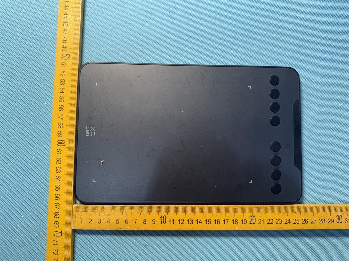
2AKDT-DECOMINI7WV2
Dec 12, 2025Drawing Tablet
Equipment Class
DTS - Digital Transmission System2AKDT-ACK05B
Apr 26, 2024Wireless Shortcut Remote
Equipment Class
DTS - Digital Transmission System
2AKDT-MT0962B
May 04, 2023Drawing Tablet
Equipment Class
DTS - Digital Transmission System