2AL6XWAP380-C14x4 AX Dual-band AP
Emplus Technologies, Inc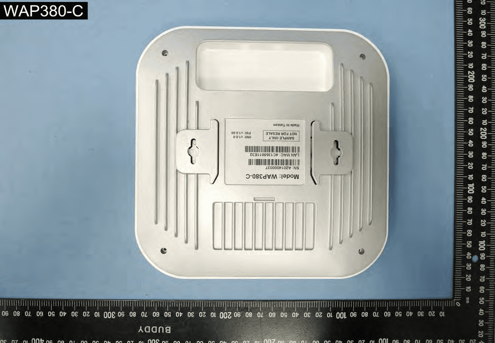
Click to zoom
Application Details
- Equipment Class
- DTS - Digital Transmission System
- Date of Grant
- Apr 19, 2021
- Application Purpose
- Original Equipment
- Date of Application
- Apr 10, 2021
- Equipment Note
- 4x4 AX Dual-band AP
- Frequency Range
- 2412.00000000 - 2462.00000000
- Company
- Emplus Technologies, Inc
- Country
- Taiwan
Documents & Files
Document Text
Text extracted from the exhibit documents filed with the FCC. Open a document above to read the original.
Users Manual
0 User Manual WAP380-C Version 1.0 1 IMPORTANT To install this Access Point Please refer to the Quick Installation Guide included in the product packaging 2 Chapter1 Product Overview 3 Introduction Key Features ・Supports IEEE802.11ac/a/b/g/n/ax wireless standards ・Four 2.4 GHz Metal PIFA Antennas ・Four 5 GHz Metal PIFA Antennas ・Support MU-MIMO / OFDMA function ・Support Tx Beamforming to enlarge the transmitting distance. ・IEEE802.11 PoE af/at Input design with Gigabit port supports. ・More customized items on Band Steering for intelligent Management. ・Secured Guest Network option available The AP is 802.11 ax ac/a/b/g/n Indoor Access Point with speeds up to 1200 Mbps on 2.4GHz and 2400 Mbps on 5GHz band. It can be configured as an Access Point, or WDS (AP, Station). The AP is an affordable solution which is built in high-powered radios and long-range settings to replace the ordinary Access Points that do not have the range and reach to connect to a growing number of wireless users. With 11ax features, the Access Point could reduce the handling period on client devices and network with more client devices at the same time. Meanwhile, the beamforming will gather energy to a specific direction and increase the transmitting distance. 4 Physical Interface (WAP380-C) 5 Physical & Environment Power Source DC Input: 12 VDC/2.5A PoE: compatible with 802.3af/at 54Vdc/0.6A Internal High Gain Antenna (Peak Gain) ~5.01dBi 2.4GHz antennas ~5.19dBi 5GHz antennas Interface 1 x 10/100/1000/2500Mbps Ethernet Port with 802.3af/at PoE 1 x DC power connector 1 x reset button Dimensions (W x D x H) 205x205x34 mm Mounting Ceiling, T-Rail, Wall and Pole mount Environment Operating temperature: 0°C~40°C Operating humidity: 0%~90% typical Technical Specifications Storage temperature: -40°C~70°C 6 Mounting 7 8 Pole Mount an Access Point 6) Slide the pole mount base into the slot of the Access Point. 7) Attaching the Straps to the Pole Mount Bracket 8) Lock and tighten the strap to secure the pole mount bracket to the pole. 9 Applications Wireless LAN (WLAN) products are easy to install and highly efficient. The following list describes some of the many applications made possible through the power and flexibility ofWLANs: Difficult-to-Wire Environments: There are many situations where wires cannot be installed, deployed easily, or cannot be hidden from view. Older buildings, sites with multiple buildings, and/or areas that make the installation of a Ethernet-based LAN impossible, impractical or expensive are sites where WLAN can be a network solution. Temporary Workgroups: Create temporary workgroups/networks in more open areas within a building; auditoriums, amphitheaters classrooms, ballrooms, arenas, exhibition centers, or temporary offices where one wants either a permanent or temporary Wireless LAN established. The Ability to Access Real-Time Information: Doctors/Nurses, Point-of-Sale Employees, and/or Warehouse Workers can access real-time information while dealing with patients, serving customers, and/or processing information. Frequently Changing Environments: Set up networks in environments that change frequently (i.e.: Show Rooms, Exhibits, etc.). Small Office and Home Office (SOHO) Networks: SOHO users require a cost-effective, easy, and quick installation of a small network. Training/Educational Facilities: Training sites at corporations or students at universities use wireless connectivity to exchange information between peers and easily access information for learning purposes. EnGenius Technologies 1580 Scenic Ave. Costa Mesa, CA 92626 Contact Name/Title: Eric Chen / Product Marketing Contact Information (Email/Tel):[email protected]/ 714-432-8668 10 Chapter2 Before You Begin 11 Computer Settings Windows XP/Windows 7/Windows 8/Windows 10 In order to use the Access Point, you must first configure the TCP/IPv4connectionofyourWindowsOScomputersystem. 1a. Click the Start button and open the Control Panel WindowsXP Windows7 1b. Move your mouse to the lower right hot corner to display the Charms Bar and select the Control Panel in Windows 8OS. Windows 8 1c. In Windows10, click Start to select All APP stoenter the folder of Windows system for selecting Control Panel. Windows 10 12 2a. In Windows XP, click Network Connections. 2b.In Windows7/Windows8/Windows10, click View Network Status and Tasks in the Network and Internetsection, then select Change adapter settings. 3. Right click on Local Area Connection and select Properties. 4. Select Internet Protocol Version 4 (TCP/IPv4) and then select Properties. 5. Select Use the following IP address and enter an IP address that is different from the Access Point and Subnet mask, then click OK. 13 Note: EnsurethattheIPaddressandSubnetmaskare on the same subnet as the device. For example: WAP380-C IP address: 192.168.1.1 PC IP address: 192.168.1.2–192.168.1.255 PC Subnet mask: 255.255.255.0 14 Apple Mac OSX 1. Go to System Preferences (Which can be opened in the Applications folder or selecting it in the Apple Menu). 2. Select Network in the Internet & Network section. 3. HighlightEthernet. 4. In Configure IPv4, select Manually. 5. Enter an IP address that is different from the Access Point and Subnet mask then press OK. Note: Ensure that the IP address and Subnet mask are on the same subnet as the device. For example: A device IP address: 192.168.1.1 PCIPaddress: 192.168.1.2–192.168.1.255 PCSubnetmask:255.255.255.0 6. Click Apply when done. 15 Chapter 3 Configuring Your Access Point 16 ConfiguringYourAccessPoint This section will show you how to configure the device using the web-based configuration interface. Default Settings Please use your Ethernet port or wireless network adapter to connect the Access Point. IP Address 192.168.1.1 Username / Password none Web Configuration 1. Open a web browser (Internet Explorer/Firefox/Safari/ Chrome) and enter the IP Address http://192.168.1.1 Note: If you have changed the default LAN IP Address of The A…
Text truncated - open the document above for the full version.
Cover Letter(s)
SCS-F019: Confidentiality Request Letter Page 1 of 2 Rev 7.0 775 Montague Expressway Milpitas, CA 95035 Tel: 408-526-1188 Fax: 408-526-1088 Email: [email protected] Website: https://www.cps.bureauveritas.com/ Confidentiality Request Letter Reason for Amendment (current / obsolete) Revision History Approved Date From To Initial Release (obsolete) 1.0 1.0 Nov-14-2006 Adding CFR 2.459 (obsolete) 1.0 2.0 August – 11 - 2008 Updated company template & Added text box (obsolete) 2.0 3.0 Jan-31-2012 Added IC confidentiality letter form (obsolete) 3.0 4.0 March-26-2015 Corrections to STC form. Added reference to KDB (obsolete) 4.0 5.0 Nov-19-2015 Updated company logo (current) 5.0 6.0 Jun-26-2019 Updated References and Contact Info 6.0 7.0 Aug-30-2020 SCS-F019: Confidentiality Request Letter Page 2 of 2 Rev 7.0 Emplus Technologies, Inc Bld B, 10F, No.209, Sec.1, Nangang Rd. , Taipei City, Taiwan February 20, 2021 To: Federal Communications Commission Authorization and Evaluation Division 7435 Oakland Mills Road Columbia, MD 21046-1609 Cc: Bureau Veritas Consumer Products Services Inc. 775 Montague Expressway Milpitas, CA 95035 Subject: Confidentiality Request for FCC ID: 2AL6XWAP380-C1 Pursuant to CFR 47 sections 0.457 and 0.459, we respectfully request permanent confidential treatment of the following Exhibits accompanying this application be held confidential: Type of Confidentiality Requested Exhibit Short Term Permanent Block Diagram Short Term External Photos Short Term Permanent Internal Photos Short Term Permanent Operational Description/ Theory of Operation Short Term Permanent Parts List Short Term Permanent Tune-Up Procedure Short Term Permanent Schematics Short Term Test Setup Photos Short Term Permanent User’s Manual The above materials contain trade secrets and proprietary information not customarily released to the public. The public disclosure of these materials may be harmful to the applicant and provide unjustified benefits to its competitors. Permanent Confidentiality: The applicant requests the exhibits listed above as permanently confidential be permanently withheld from public review due to materials that contain trade secrets and proprietary information not customarily released to the public. Short-Term Confidentiality: To avoid premature release of sensitive information prior to marketing or release of the product to the public, the applicant requests the following documents contained in this certification application be temporarily withheld from public disclosure for an initial period of 45 or 180 days; or for a specified date of not to exceed 180 days from the Grant Date The applicant understands that disclosure of this application and all accompanying documentation will not be made before the date of the Grant for this application. Sincerely, Client’s signature: Client’s name & title: Charlie Chen/Product Marketing Contact information / address: Bld B, 10F, No.209, Sec.1, Nangang Rd. , Taipei City, Taiwan i Permanent confidentiality may be requested in accordance with FCC KDB 726920
Cover Letter(s)
Emplus Technologies, Inc Bld B, 10F, No.209, Sec.1, Nangang Rd., Taipei City, Taiwan WIFI Channel 12 & 13 Declaration Letter To whom it may concern : We have declared below featured for FCC equipment authorization in regard to 802.11b/g/n channel 12 & 13 operating capability for FCC ID : 2AL6XWAP380-C1 Please check Product hardware does not have the capability to operate on channel 12 & 13 Product hardware has the capability to operate on channel 12 & 13. However , these 2 channels will be disabled via software and user will not able to enable these 2 channels Product hardware has the capability to operate on channel 12 & 13. And meeting KDB 594280 D01 requirement. Pls explain detail here. _________________ Others Pls explain detail here. Signature: Date: February 20, 2021 Name/Title: Charlie Chen/Product Marketing Company Name: Emplus Technologies, Inc Address: Bld B, 10F, No.209, Sec.1, Nangang Rd., Taipei City, Taiwan TEL: +886-2-2782-1216 Email: [email protected]
External Photos
1 of 5 External Photos Model Number: WAP380-C 2 of 5 EUT Photo (1) EUT Photo (2) 3 of 5 EUT Photo (3) EUT Photo (4) 4 of 5 EUT Photo (5) EUT Photo (6) 5 of 5 EUT Photo (7)
ID Label/Location Info
Label Format: Label Position:
Internal Photos
1 of 10 Internal Photos Model Number: WAP380-C 2 of 10 EUT Photo (1) EUT Photo (2) WLAN 2.4G ANT-0. WLAN 2.4G ANT-1. WLAN 2.4G ANT-2. WLAN 2.4G ANT-3. WLAN 5G ANT-3. WLAN 5G ANT-2. WLAN 5G ANT-1. WLAN 5G ANT-0. 3 of 10 EUT Photo (3) EUT Photo (4) 4 of 10 EUT Photo (5) EUT Photo (6) 5 of 10 EUT Photo (7) EUT Photo (8) Conductive foam 6 of 10 EUT Photo (9) EUT Photo (10) 7 of 10 EUT Photo (11) EUT Photo (12) 8 of 10 EUT Photo (13) EUT Photo (14) 9 of 10 EUT Photo (15) EUT Photo (16) 10 of 10 EUT Photo (17) EUT Photo (18)
RF Exposure Info
MPE Report Applicant : Emplus Technologies, Inc Product Type : 4x4 AX Dual-band AP Trade Name : emplus Model Number : WAP380-C Applicable Standard : IEEE Std.C95.1 Received Date Test Period Issue Date 47 CFR § 2.1091 / 47 CFR § 1.1310 : Feb. 08, 2021 : Feb. 20, 2021 : Mar. 12, 2021 Issued by Approved By : (Kris Pan) A Test Lab Techno Corp. No. 140-1, Changan Street, Bade District, Taoyuan City 33465, Taiwan (R.O.C.) Tel:+886-3-2710188 / Fax:+886-3-2710190 Taiwan Accreditation Foundation accreditation number: 1330 Test Firm MRA designation number: TW0010 Note: 1.The test results are valid only for samples provided by customers and under the test conditions described in this report. 2.This report shall not be reproduced except in full, without the written approval of A Test Lab Technology Corporation. 3.The relevant information is provided by customers in this test report. According to the correctness, appropriateness or completeness of the information provided by the customer, if there is any doubt or error in the information which affects the validity of the test results, the laboratory does not take the responsibility. Report Number: 2103FS13 Rev.00 Page 1 of 14 Revision History Rev. Issued Date Revisions Revised By 00 Mar. 12, 2021 Initial Issue Nicole Chu Report Number: 2103FS13 Rev.00 Page 2 of 14 Contents 1.Reference Applicable Standard .......................................................................................................... 4 2.Description of Equipment under Test (EUT) ....................................................................................... 5 3.Human Exposure Assessment ............................................................................................................ 7 4.Power Density Limit – RF Exposure Evaluation ................................................................................. 8 4.1Conducted Power ............................................................................................................................... 9 5.Tes t Result ........................................................................................................................................ 14 Report Number: 2103FS13 Rev.00 Page 3 of 14 1. Reference Applicable Standard Standard Description Version ANSI/IEEE C95.1 American National Standard safety levels with respect to human exposure to radio frequency electromagnetic fields, 300 KHz to 100 GHz, New York. 1992 47 CFR Part §2.1091 Radiofrequency radiation exposure evaluation: mobile devices. - 47 CFR Part §1.1310 Radiofrequency radiation exposure limits. - Report Number: 2103FS13 Rev.00 Page 4 of 14 2. Description of Equipment under Test (EUT) Applicant Emplus Technologies, Inc Bld B, 10F, No.209 Nangang Rd., Taipei City, Taiwan Manufacturer Emplus Technologies., Inc. 10F., Building B, No.209, Sec. 1, Nangang Rd., Nangang Dist., Taipei City 115, Taiwan (R.O.C.) Product Type 4x4 AX Dual-band AP Trade Name emplus Model Number WAP380-C FCC ID 2AL6XWAP380-C1 Frequency Range Operate Band Frequency Range (MHz) IEEE 802.11b / 802.11g 2412 - 2462 IEEE 802 11n 2.4 GHz 20 MHz(256-QAM) IEEE 802 11ax 2.4 GHz 20 MHz 2412 - 2462 IEEE 802.11n 2.4 GHz 40 MHz (256-QAM) IEEE 802.11ax 2.4 GHz 40 MHz 2422 - 2452 IEEE 802.11a U-NII Band I 5180 - 5240 IEEE 802.11a U-NII Band III 5745 - 5825 IEEE 802.11ac 5 GHz 20 MHz U-NII Band I IEEE 802.11ax 20 MHz U-NII Band I 5180 - 5240 IEEE 802.11ac 5 GHz 20 MHz U-NII Band III IEEE 802.11ax 20 MHz U-NII Band III 5745 - 5825 IEEE 802.11ac 5 GHz 40 MHz U-NII Band I IEEE 802.11ax 40 MHz U-NII Band I 5190 - 5230 IEEE 802.11ac 5 GHz 40 MHz U-NII Band III IEEE 802.11ax 40 MHz U-NII Band III 5755 - 5795 IEEE 802.11ac 80 MHz IEEE 802.11ax 80 MHz 5210 5775 Antenna Information Model Type Max. Gain (dBi) 5718A0514300 PIFA Antenna 2412 - 2472 3.70 5718A0515300 PIFA Antenna 2412 - 2472 4.08 5718A0516300 PIFA Antenna 2412 - 2472 4.12 5718A0517300 PIFA Antenna 2412 - 2472 5.01 G ANT 4.25 Directional 10.26 Report Number: 2103FS13 Rev.00 Page 5 of 14 Antenna Information Model Type Max. Gain (dBi) 5718A0518300 PIFA Antenna 5150~5250 5.13 5725~5850 5.19 5718A0522300 PIFA Antenna 5150~5250 4.26 5725~5850 3.81 5718A0520300 PIFA Antenna 5150~5250 4.03 5725~5850 4.56 5718A0521300 PIFA Antenna 5150~5250 5.04 5725~5850 5.04 G ANT 5150~5250 4.64 5725~5850 4.68 Directional 5150~5250 10.65 5725~5850 10.69 Antenna Delivery IEEE 802.11b: 4TX / 4RX (CDD) IEEE 802.11g : 4TX / 4RX (CDD) IEEE 802.11n 2.4 GHz 20 MHz / 40 MHz: 4TX / 4RX (STBC / Beamforming on) IEEE 802.11ax 2.4 GHz 20 MHz / 40 MHz: 4TX / 4RX (STBC / Beamforming on) IEEE 802.11a: 4TX / 4RX(CDD) IEEE 802.11ac 20 MHz / 40 MHz / 80 MHz: 4TX / 4RX (STBC / Beamforming on) IEEE 802.11ax 20 MHz / 40 MHz / 80 MHz: 4TX / 4RX (STBC / Beamforming on) RF Evaluation 0.419 mW/cm 2 Operate Temp. Range 0 ~ +40°C The above equipment was tested by A Test Lab Techno Corp. For compliance with the requirements set forth in 47 CFR § 2.1091 / 47 CFR § 1.1310. The results of testing in this report apply only to the product/system, which was tested. Other similar equipment will not necessarily produce the same results due to production tolerance and measurement uncertainties. Data re-use Description: In accordance with KDB 484596 D01 c) Spot-check test data shall be based on Max. Output Power and Transmitter Radiated Emissions in the original FCC ID filing, should remain within the tune-up tolerance range specified for the product, and should be compliant with applicable rule part(s), After evaluation above, data re-use is applicable. Original FCC ID: 2AL6XWAP380-C Report Number: 2103FS13 Rev.00 Page 6 of 14 3. Human Exposure Assessment Due to the design and installation of this product, it is not possible to conduct SAR evaluation. This is because client either manufactures or supplies the antenna(s) that will be used in the installation of this product. Therefore, this product will be evaluated as a mobile device per 47 CFR § 1.1310 titled “Radiofrequency radiatio…
Text truncated - open the document above for the full version.
Test Report
Emplus Technologies, Inc Declaration Date: 2021/03/22 To Whom It May Concern: We, Emplus Technologies, Inc, declare that the product of FCC ID: 2AL6XWAP380-C1 and FCC ID: 2AL6XWAP380-C only one difference is antenna transmit from diversity change to CDD, this difference is through by adjust power setting to meet standard requirement. And we take full responsibility that the test data as referenced per FCC ID: 2AL6XWAP380-C represents compliance for the new FCC ID: 2AL6XWAP380-C1. The date of original grant are 09/01/2020 and 11/26/2020. Any question regarding this declaration, please do not hesitate to contact us. Sincerely, Signature ___________________ Name/Title: Charlie Chen/Product Marketing Company Name: Emplus Technologies, Inc Address: Bld B, 10F, No.209, Sec.1, Nangang Rd. , Taipei City, Taiwan TEL: +886-2-2782-1216 Email: [email protected]
Test Report
Note: 1.The test results are valid only for samples provided by customers and under the test conditions described in this report. 2.This report shall not be reproduced except in full, without the written approval of A Test Lab Technology Corporation. 3.The relevant information is provided by customers in this test report. According to the correctness, appropriateness or completeness of the information provided by the customer, if there is any doubt or error in the information which affects the validity of the test results, the laboratory does not take the responsibility. RF Test Report Applicant : Emplus Technologies, Inc Product Type : 4x4 AX Dual-band AP Trade Name : emplus Model Number : WAP380-C Applicable Standard : FCC 47 CFR PART 15 SUBPART C ANSI C63.10:2013 Received Date : Feb. 08, 2021 Test Period : Feb. 18 ~ Feb. 23, 2021 Issued Date : Apr. 15, 2021 Issued by A Test Lab Techno Corp. No. 140-1, Changan Street, Bade District, Taoyuan City 33465, Taiwan (R.O.C.) Tel:+886-3-2710188 / Fax:+886-3-2710190 Taiwan Accreditation Foundation accreditation number: 1330 Frequency Range : 9 kHz to 40 GHz Test Firm MRA designation number: TW0010 Report Number: 2103FR16 Rev.01 Page 1 of 149 Revision History Rev. Issued Date Revisions Revised By 00 Mar. 10, 2021 Initial Issue Tobey Cheng 01 Apr. 15, 2021 Update chapter 1.1 (P.5) Update chapter 2 (P.7) Tobey Cheng Report Number: 2103FR16 Rev.01 Page 2 of 149 Ve r i f i c a t i o n o f C o m p l i a n c e Applicant : Emplus Technologies, Inc Product Type : 4x4 AX Dual-band AP Trade Name : emplus Model Number : WAP380-C FCC ID : 2AL6XWAP380-C1 EUT Rated Voltage : DC 12 V, 2.5 A (DC Power Adapter) DC 54 V, 0.6 A (PoE injector (802.3af/at)) Test Voltage : 120 Vac / 60 Hz Applicable Standard : FCC 47 CFR PART 15 SUBPART C ANSI C63.10:2013 Test Result : Complied Performing Lab. : A Test Lab Techno Corp. No. 140-1, Changan Street, Bade District, Taoyuan City 33465, Taiwan (R.O.C.) Tel:+886-3-2710188 / Fax:+886-3-2710190 Taiwan Accreditation Foundation accreditation number: 1330 http://www.atl-lab.com.tw/e-index.htm A Test Lab Techno Corp. tested the above equipment in accordance with the requirements set forth in the above standards. All indications of Pass/Fail in this report are opinions expressed by A Test Lab Techno Corp. based on interpretations and/or observations of test results. The test results show that the equipment tested is capable of demonstrating compliance with the requirements as documented in this report. Approved By : (Manager) (Ken Yang) Report Number: 2103FR16 Rev.01 Page 3 of 149 TABLE OF CONTENTS 1 General Information .................................................................................................................... 5 1.1. Summary of Test Result ........................................................................................................ 5 1.2. Measurement Uncertainty ..................................................................................................... 6 2 EUT Description .......................................................................................................................... 7 3 Test Methodology ....................................................................................................................... 9 3.1. Mode of Operation ................................................................................................................ 9 3.2. EUT Test Step...................................................................................................................... 11 3.3. Configuration of Test System Details .................................................................................. 12 3.4. Test Instruments ................................................................................................................. 14 3.5. Test Site Environment ......................................................................................................... 15 4 Measurement Procedure .......................................................................................................... 16 4.1. AC Power Line Conducted Emission Measurement ............................................................ 16 4.2. Radiated Emission Measurement ....................................................................................... 18 4.3. Maximum Conducted Output Power Measurement ............................................................. 22 4.4. 6 dB RF Bandwidth Measurement ...................................................................................... 23 4.5. Maximum Power Spectral Density Measurement ................................................................ 24 4.6. Out of Band Conducted Emissions Measurement .............................................................. 25 4.7. Antenna Measurement ....................................................................................................... 26 5 Test Results ............................................................................................................................... 27 Annex A. Conducted Emission .................................................................................................... 27 Annex B. Conducted Test Results ............................................................................................... 29 Annex C. Radiated Emission Measurement ................................................................................ 61 Report Number: 2103FR16 Rev.01 Page 4 of 149 1 General Information 1.1. Summary of Test Result Standard Item Result Remark 15.207 AC Power Conducted Emission PASS ----- 15.247(d) Transmitter Radiated Emissions PASS Note 1 15.247(b)(3) Max. Output Power PASS Note 1 15.247(a)(2) 6 dB RF Bandwidth PASS Note 2 15.247(e) Maximum Power Spectral Density PASS Note 2 15.247(d) Out of Band Conducted Spurious Emission PASS Note 2 15.203 Antenna Requirement PASS Note 2 Note 1:Only verify part of the data, the other test data…
Text truncated - open the document above for the full version.
Test Report
Note: 1.The test results are valid only for samples provided by customers and under the test conditions described in this report. 2.This report shall not be reproduced except in full, without the written approval of A Test Lab Technology Corporation. 3.The relevant information is provided by customers in this test report. According to the correctness, appropriateness or completeness of the information provided by the customer, if there is any doubt or error in the information which affects the validity of the test results, the laboratory does not take the responsibility. RF Test Report Applicant : Emplus Technologies, Inc Product Type : 4x4 AX Dual-band AP Trade Name : emplus Model Number : WAP380-C Applicable Standard : FCC 47 CFR PART 15 SUBPART C ANSI C63.10:2013 Received Date : May 13, 2020 Test Period : Jun. 03 ~ Jul. 10, 2020 Issued Date : Aug. 19, 2020 Issued by A Test Lab Techno Corp. No. 140-1, Changan Street, Bade District, Taoyuan City 33465, Taiwan (R.O.C.) Te l:+886-3-2710188 / Fax:+886-3-2710190 T aiwan Accreditation Foundation accreditation number: 1330 Frequency Range : 9 kHz to 40 GHz Test Firm MRA designation number: TW0010 Report Number: 2008FR15 Rev.00 Page 1 of 422 Revision History Rev. Issued Date Revisions Revised By 00 Aug. 19, 2020 Initial Issue Snow Wang Report Number: 2008FR15 Rev.00 Page 2 of 422 Verification of Compliance Applicant : Emplus Technologies, Inc Product Type : 4x4 AX Dual-band AP Trade Name : emplus Model Number : WAP380-C FCC ID : 2AL6XWAP380-C EUT Rated Voltage : DC 12 V, 2.5 A (DC Power Adapter) DC 54 V, 0.6 A (PoE injector (802.3af/at)) Test Voltage : 120 Vac / 60 Hz Applicable Standard : FCC 47 CFR PART 15 SUBPART C ANSI C63.10:2013 Test Result : Complied Performing Lab. : A Test Lab Techno Corp. No. 140-1, Changan Street, Bade District, Taoyuan City 33465, Taiwan (R.O.C.) Te l:+886-3-2710188 / Fax:+886-3-2710190 T aiwan Accreditation Foundation accreditation number: 1330 http://www.atl-lab.com.tw/e-index.htm A Test Lab Techno Corp. tested the above equipment in accordance with the requirements set forth in the above standards. All indications of Pass/Fail in this report are opinions expressed by A Test Lab Techno Corp. based on interpretations and/or observations of test results. The test results show that the equipment tested is capable of demonstrating compliance with the requirements as documented in this report. Approved By : (Manager) (Jeremy Lin) Report Number: 2008FR15 Rev.00 Page 3 of 422 TABLE OF CONTENTS 1 General Information ......................................................................................................... 5 1.1. Summary of Test Result ............................................................................................. 5 1.2. Measurement Uncertainty .......................................................................................... 6 2 EUT Description................................................................................................................ 7 3 Test Methodology ............................................................................................................. 9 3.1. Mode of Operation ...................................................................................................... 9 3.2. EUT Test Step ........................................................................................................... 16 3.3. Configuration of Test System Details ........................................................................ 17 3.4. Test Instruments ....................................................................................................... 19 3.5. Test Site Environment............................................................................................... 20 4 Measurement Procedure ................................................................................................ 21 4.1. AC Power Line Conducted Emission Measurement ................................................. 21 4.2. Radiated Emission Measurement ............................................................................. 23 4.3. Maximum Conducted Output Power Measurement .................................................. 27 4.4. 6 dB RF Bandwidth Measurement ............................................................................ 28 4.5. Maximum Power Spectral Density Measurement ..................................................... 29 4.6. Out of Band Conducted Emissions Measurement .................................................... 30 4.7. Antenna Measurement ............................................................................................. 31 5 Test Results .................................................................................................................... 32 Annex A. Conducted Emission ......................................................................................... 32 Annex B. Conducted Test Results .................................................................................... 36 Annex C. Radiated Emission Measurement ................................................................... 241 Report Number: 2008FR15 Rev.00 Page 4 of 422 1 General Information 1.1. Summary of Test Result Standard Item Result Remark 15.207 AC Power Conducted Emission PASS ----- 15.247(d) Transmitter Radiated Emissions PASS ----- 15.247(b)(3) Max. Output Power PASS ----- 15.247(a)(2) 6 dB RF Bandwidth PASS ----- 15.247(e) Maximum Power Spectral Density PASS ----- 15.247(d) Out of Band Conducted Spurious Emission PASS ----- 15.203 Antenna Requirement PASS ----- Decision Rule ■ Uncertainty is not included. □ Uncertainty is included. Standard Description CFR47, Part 15, Subpart C Intentional Radiators ANSI C63. 10: 2013 American National Standard of Procedures for Compliance Testing of Unlicensed Wireless Devices KDB 558074 D01 15.247 Meas Guidance v05r02 GUIDANCE FOR COMPLIANCE MEASUREMENTS ON DIGITAL TRANSMISSION SYSTEM, FREQUENCY HOPPING SPREA…
Text truncated - open the document above for the full version.
Test Report
Beamforming on Mode 4: IEEE 802.11n 2.4 GHz 20 MHz Continuous TX mode_ANT-0 2412 MHz 2437 MHz 2462 MHz Report Number: 2008FR15 Rev.00 Page 114 of 422 Mode 5: IEEE 802.11n 2.4 GHz 40 MHz Continuous TX mode_ANT-0 2422 MHz 2437 MHz 2452 MHz Report Number: 2008FR15 Rev.00 Page 115 of 422 Mode 6: IEEE 802.11ax 2.4 GHz 20 MHz Continuous TX mode_ANT-0 …
Text truncated - open the document above for the full version.
Contact Information
Applicant
Charlie Chen
Test Firm
Eurofins E&E Wireless Taiwan Co., LtdFly LU
Technical Specifications
| # | Rule Parts | Frequency Range | Power Output |
|---|---|---|---|
| 1 | 15C | 2.41 GHz - 2.46 GHz | 360.00 mW |
Other Applications from Emplus Technologies, Inc
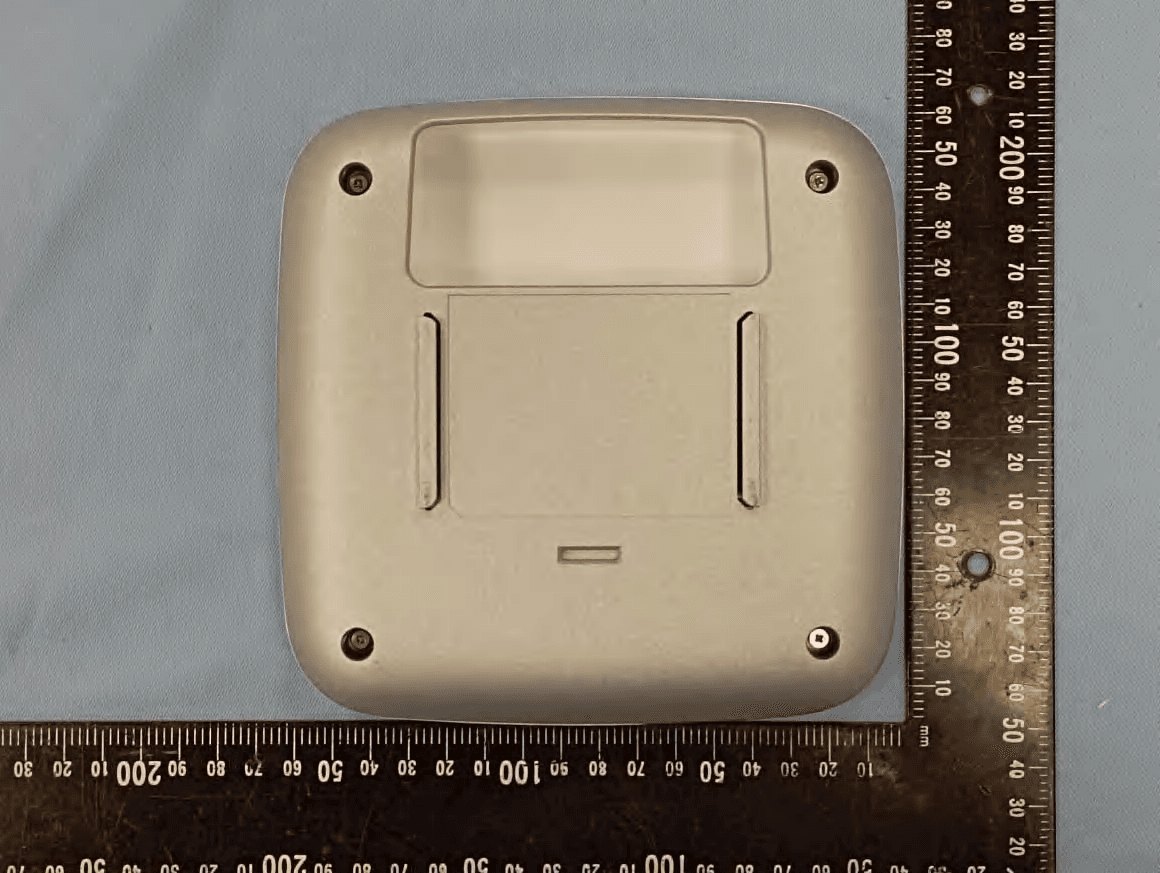
2AL6XWAP388
Jan 18, 202311AX Dual band AP
Equipment Class
DTS - Digital Transmission System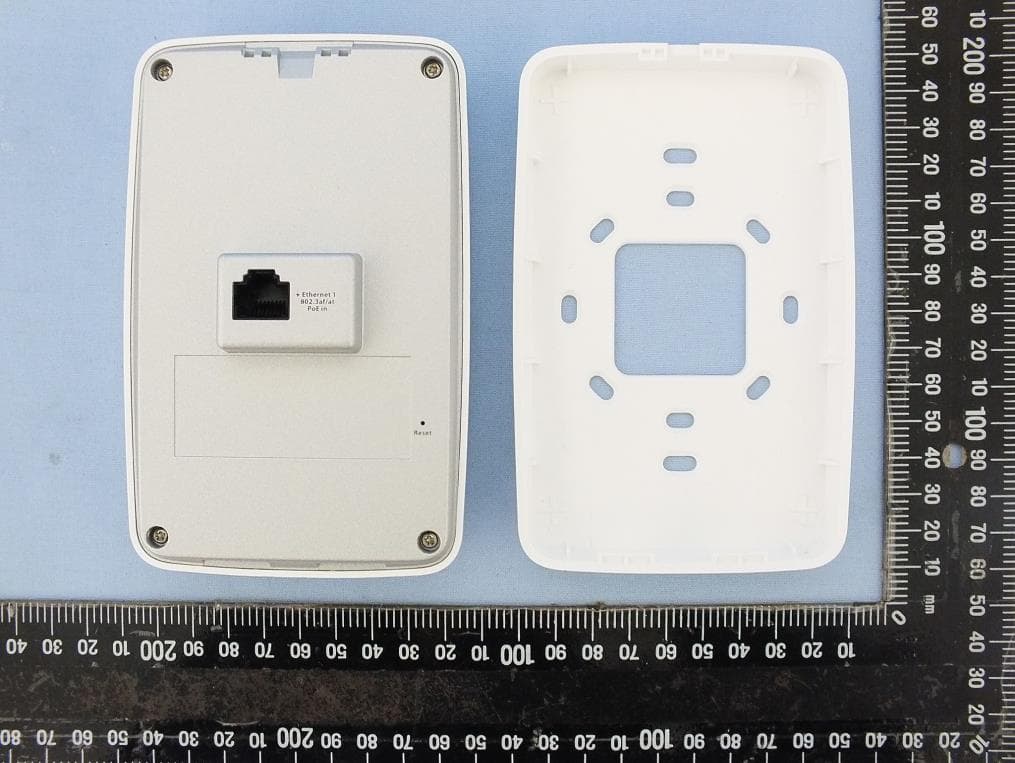
2AL6XWAP581
Jun 08, 2022802.11ax 2x2 2-Streams Dual Concurrent Dual radios Wall Plate Access Point / 802.11ax Cloud Managed AP
Equipment Class
DTS - Digital Transmission System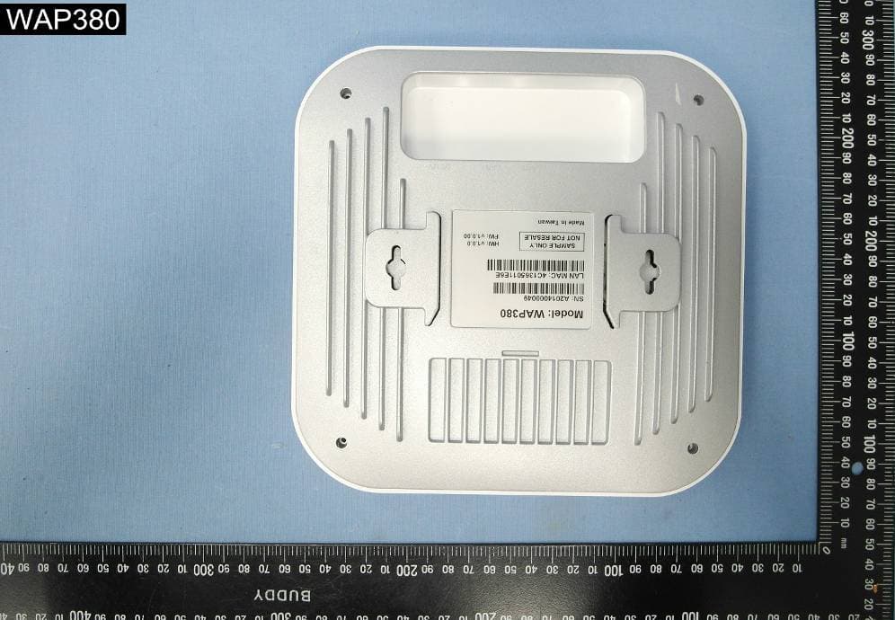
2AL6XWAP380
Aug 24, 20204x4 AX Dual-band AP
Equipment Class
NII - Unlicensed National Information Infrastructure TX