2ALS8-BT2928Ninebot Engine Speaker
Ninebot (Changzhou) Tech Co., Ltd.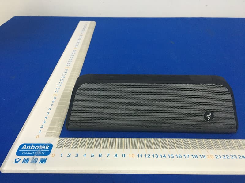
Click to zoom
Application Details
- Equipment Class
- DSS - Part 15 Spread Spectrum Transmitter
- Date of Grant
- Jul 06, 2020
- Application Purpose
- Original Equipment
- Date of Application
- Jul 06, 2020
- Equipment Note
- Ninebot Engine Speaker
- Frequency Range
- 2402.00000000 - 2480.00000000
- Country
- China
Documents & Files
Document Text
Text extracted from the exhibit documents filed with the FCC. Open a document above to read the original.
Users Manual
Welcome Engine Speaker User Manual Thank you for choosing Ninebot Engine Speaker (hereinafter referred to “the speaker"). This product can be connected to mobile phones to play music, and can also be connected to many Segway-Ninebot vehicle models. When connected to vehicles, it can simulate different engine sound effects. Enjoy these interesting and cool sound effects. The manufacturer reserves the right to make changes to the product and update this manual at any time. Product parameters are subject to change without prior notice. Visit www.segway.com to download the latest user materials *Please check the packaging contents carefully. In case of any missing or damaged items, please call the after-sales service. User ManualUSB Type-C Charger Cable The Speaker Base Contents 5 1 Product Diagram 2 Installation 3 Connect to a Vehicle (Vehicle Mode) 4 Connect to a Mobile Phone (Music Mode) 5 Charging 6 Button Functions 7. Meanings of Indicators 8 Applicable Models 9. Specifications 10. FAQs 11. Precautions 12. Trademarks and Legal Statements 13. After-sales Policy 1 2 3 4 4 5 5 6 6 7 7 8 1 Product Diagram Bottom viewBase Horn Indicator Power switch Volume - Pause/Next Mode USB Type-C Diaphragm on both sides Bracket hook Bracket hook Bracket lock Bracket lock Anti-slip strip Anti-slip strip Storage slot Strap Disassembly switch Strap hook Bracket hook Top view 1 Volume + 1. Place the base in a proper position (as shown above, the bracket hook is located below) and wrap the strap around the vehicle body. 2. Fasten the strap on the strap hook of the base. Make sure it is firmly fastened. 3. Press the remaining part of the strap into the storage slot. 1. Align the holes on the bottom of the speaker with those in the base. 2. Press down until you hear a "clicking" sound. 3. When removing the speaker, press the disassembly switch while lifting the speaker upward. 2 Installation Install the Base Install/Remove the Speaker 2 This chapter takes Ninebot GoKart Pro as an example. The specific installation steps depend on the vehicle model. 3 Connect to a Vehicle (Vehicle Mode) NOTE: Please ensure that the vehicle to be connected is turned on and the firmware has been upgraded to the latest version in the Segway-Ninebot App. 3 1. Press the power switch to turn on the speaker. The indicator is white by default. If the indicator is blue, please press the Mode button to switch to the white indicator. Tip: After powered on, the speaker has two modes: vehicle mode (white light with engine sound) and music mode (blue light with chord sound e ect). 2. Press and hold the Mode button to start pairing. Please operate the vehicle according to the voice prompt to complete the pairing. Once the pairing succeeds, the speaker will automatically connect to the vehicle, and the indicator will be solid white. If the pairing fails, repeat this step. Note: · When connecting, please ensure that there is only one active vehicle within the range of the Bluetooth (about 10 m) and the Bluetooth of the vehicle is not connected, otherwise the connection may not be successful. · If the vehicle to be connected is Ninebot eScooter or Ninebot eMoped, please disable the "Ninebot AirLock" function in Segway-Ninebot App, otherwise the speaker may not be connected. · The speaker automatically connects the paired vehicle. If you need to connect the speaker to another vehicle, please repeat this step. 3. After the speaker is successfully connected, press "Next" to change the engine sound e ect. Tip: The speaker has 4 kinds of engine sound e ects: single-cylinder engine, double-cylinder engine, V8 engine and V12 engine. 5 Charging 4 Connect to a Mobile Phone (Music Mode) 4 1. Press the power switch to turn on the speaker. 2. Short press the Mode button until the blue indicator is on and the chord sound e ect is sounded. 3. Enable the Bluetooth on your mobile phone and connect to "Ninebot Engine Speaker". After pairing, the speaker can play music from your mobile phone. When the indicator flashes red, the speaker has low battery, please charge it immediately. 1. Open the rubber cover of the charging port; 2. Insert the charging cable to charge. The indicator is solid red during charging. 3. When the battery is full, the indicator will be solid green. Disconnect the charging cable when finished. 6 Button Functions 7 Meanings of Indicators Short press to power on. Short press to increase the volume by one bar. Short press to reduce the volume by one bar. In vehicle mode, short press to switch sound e ects. Short press to switch vehicle mode and music mode. Long press to power o . Self-balancing vehicles Kickscooter Electric Motorbike Ninebot GoKart Electric Bike Ninebot S Ninebot miniPRO Ninebot S-PLUS Ninebot Dynamic Ninebot S-Max Mi Electric Scooter Ninebot KickScooter ES1/ES2/ES3/ES4 Ninebot KickScooter 22/E25/E45 Ninebot KickScooter MAX Ninebot GoKart Kit Ninebot GoKart Pro Ninebot Kart Pro (Lamborghini Edition) Ninebot eMoped C40* Ninebot eMoped C60* Ninebot eMoped C80* Segway Dirt eBike X160 Segway Dirt eBike X260 Ninebot eScooter 80C* Ninebot eScooter 125* Ninebot eScooter 100* Ninebot eScooter 200P* Segway Dirt eBike X160 Segway Dirt eBike X260 Long press to quickly increase the volume. Long press to quickly reduce the volume. In music mode, short press to play/pause. Long press to pair in vehicle mode. Long press to disconnect/restore Bluetooth connection in music mode. 8 Applicable models Power switch Volume + Volume- Next Mode switch Vehicle mode White flashes quickly White double flashes White flashes slowly Solid white indicator Blue flashes slowly Solid blue indicator Red flashes slowly Solid red Solid green Not pairing a vehicle Vehicle is pairing Pairing a vehicle but it is not connected successfully. Connected to the vehicle successfully Not connected to mobile phone in music mode Connected to mobile phone in music mode Low battery Charging Fully charged Music mode Charging status Function 1 Function 2 Vehicle Model Indicator…
Text truncated - open the document above for the full version.
External Photos
FCC ID: 2ALS8-BT2928
ID Label/Location Info
Label Location On EUT Label Product Name: Ninebot Engine Speaker Model No.: BT2928 FCC ID: 2ALS8-BT2928 This device complies with Part 15 of the FCC Rules. Operation is subject to the following two conditions: (1) This device may not cause harmful interference, and (2) This device must accept any interference received, including interference that may cause undesired operation.
Internal Photos
FCC ID: 2ALS8-BT2928 BELANTBDR&EDRANT
Operational Description
Ninebot(Changzhou)TechCo.,Ltd DeclarationconcerningAntennaSpecification Itisherebydeclaredthattheproduct ModelNo.: BT2928 FCCID:2ALS8-BT2928 fulfillstherequirementinFCCtestrelatingtotheantennatype. ThedevicespecifiedaboveconfirmstotheFCCrecommendationsforinternalantennatype(s) describedbelow: BDR&EDR: ModelNo.ofantenna:N/A Typeofantenna:PCBAntenna Gainoftheantenna:0.5dBi Frequencyrange:2402-2480 MHz BLE: ModelNo.ofantenna:N/A Typeofantenna:PCBAntenna BDR&EDR+BLE Gainoftheantenna:0.5dBi Frequencyrange:2402-2480 MHz Themountingoftheantennaisfixedtotheradiomoduleandnootherantennashouldbeused. Companyname:Ninebot(Changzhou)TechCo.,Ltd. Address:16F-17F,BlockA,Building3,ChangwuMidRoad18#,WujinDist.,Changzhou, Jiangsu, City:Changzhou ZIP/Postalcode:N/A Country:China Place:ChangzhouDate:2020-07-07 Signature: version01
RF Exposure Info
RF EXPOSURE EVALUATION FCC ID: 2ALS8-BT2928 According to FCC 1.1310: The criteria listed in the following table shall be used to evaluate the environment impact of human exposure to radio frequency(RF) Radiation as specified in §1.1307(b): Routine SAR evaluation refers to that specifically required by §2.1093, using measurements or computer simulation. When routine SAR evaluation is not required, portable transmitters withoutput power greater than the applicable low threshold require SAR evaluation to qualify for TCB approval. Channel (MHz) Maximum output power (dBm) Tune up tolerance (dBm) Max Tune Up Power (dBm) Distance (mm) Calculation results Limit Operating Mode 2402-0.066 -0.066±1 0.93450.3843 BDR+EDR 24411.556 1.556±12.55650.5633 24802.764 2.764±1 3.76450.7493 24022.480 2.480±1 3.48050.6913 24414.255 4.255±15.25551.0483 24805.238 5.238±1 6.23851.3253 24022.460 2.460±1 3.46050.6883 BLE24401.952 1.952±12.95250.6173 24800.873 0.873±1 1.87350.4853 Test Results:PASS.
Test Report
Report No.: 18220WC00041401FCC ID: 2ALS8-BT2928Page 1 of 60 Code:AB-RF-05-a FCC TEST REPORT Client Name: Ninebot (Changzhou) Tech Co., Ltd. Address: 16F-17F, Block A, Building 3, Changwu Mid Road 18#, Wujin Dist., Changzhou, Jiangsu, China Product Name: Ninebot Engine Speaker Date: Jun. 18, 2020 Shenzhen Anbotek Compliance Laboratory Limited Report No.: 18220WC00041401FCC ID: 2ALS8-BT2928Page 2 of 60 Code:AB-RF-05-a Contents 1. General Information ............................................................................................................................................... 5 1.1. Client Information ....................................................................................................................................... 5 1.2. Description of Device (EUT) ..................................................................................................................... 5 1.3. Auxiliary Equipment Used During Test ................................................................................................... 6 1.4. Description of Test Modes ........................................................................................................................ 6 1.5. List of channels ........................................................................................................................................... 7 1.6. Description Of Test Setup ......................................................................................................................... 8 1.7. Test Equipment List .................................................................................................................................... 9 1.8. Measurement Uncertainty ....................................................................................................................... 10 1.9. Description of Test Facility ...................................................................................................................... 10 2. Summary of Test Results ................................................................................................................................... 11 3. Conducted Emission Test ................................................................................................................................... 12 3.1. Test Standard and Limit .......................................................................................................................... 12 3.2. Test Setup .................................................................................................................................................. 12 3.3. Test Procedure .......................................................................................................................................... 12 3.4. Test Data .................................................................................................................................................... 12 4. Radiation Spurious Emission and Band Edge ................................................................................................ 17 4.1. Test Standard and Limit .......................................................................................................................... 17 4.2. Test Setup .................................................................................................................................................. 17 4.3. Test Procedure .......................................................................................................................................... 18 4.4. Test Data .................................................................................................................................................... 19 5. Maximum Peak Output Power Test .................................................................................................................. 27 5.1. Test Standard and Limit .......................................................................................................................... 27 5.2. Test Setup .................................................................................................................................................. 27 5.3. Test Procedure .......................................................................................................................................... 27 5.4. Test Data .................................................................................................................................................... 27 6. 20DB Occupy Bandwidth Test ........................................................................................................................... 31 6.1. Test Standard ............................................................................................................................................ 31 6.2. Test Setup .................................................................................................................................................. 31 6.3. Test Procedure .......................................................................................................................................... 31 6.4. Test Data .................................................................................................................................................... 31 7. Carrier Frequency Separation Test ................................................................................................................... 35 7.1. Test Standard and Limit .......................................................................................................................... 35 7.2. Test Setup .................................................................................................................................................. 35 7.3. Test Procedure .......................................................................................................................…
Text truncated - open the document above for the full version.
Test Setup Photos
FCC ID: 2ALS8-BT2928 Photo of Conducted Emission Measurement Photo of Radiation Emission Test
Contact Information
Applicant
Jun Jin
Test Firm
Shenzhen Anbotek Compliance Laboratory LimitedJeff Zhu
Technical Specifications
| # | Rule Parts | Frequency Range | Power Output |
|---|---|---|---|
| 1 | 15C | 2.40 GHz - 2.48 GHz | 3.40 mW |
Other Applications from Ninebot (Changzhou) Tech Co., Ltd.
2ALS8-KS0022
May 29, 2026Segway eKickScooter Ninebot E3 Go
Equipment Class
DTS - Digital Transmission System2ALS8-OP0004
Mar 03, 2026Off-road NFC module
Equipment Class
DXX - Part 15 Low Power Communication Device Transmitter
2ALS8-KS0020
Jan 02, 2025Ninebot eKickScooter E2 Plus II
Equipment Class
DTS - Digital Transmission System
2ALS8-OP0003
Oct 25, 2023Segway USB Receiver
Equipment Class
DXX - Part 15 Low Power Communication Device Transmitter
2ALS8-OP0002
Oct 25, 2023Segway Gokart Game Kit
Equipment Class
DXX - Part 15 Low Power Communication Device Transmitter