2ALS8-KS0007Segway KickScooter
Ninebot (Changzhou) Tech Co., Ltd.
Click to zoom
Application Details
- Equipment Class
- DTS - Digital Transmission System
- Date of Grant
- Jun 07, 2022
- Application Purpose
- Original Equipment
- Date of Application
- Jun 07, 2022
- Equipment Note
- Segway KickScooter
- Frequency Range
- 2402.00000000 - 2480.00000000
- Country
- China
Documents & Files
Document Text
Text extracted from the exhibit documents filed with the FCC. Open a document above to read the original.
Users Manual
Segway KickScooter Product Manual 제품 설명서 製品マニュアル Руководство пользователя 產品手冊 EN KO JP RU 漢 ap-en.segway.com CE.00.0067.15-A EN KO JP RU 漢 EN KO JP RU 漢 The manufacturer reserves the right to make changes to the product, release firmware updates, and update this manual at any time. Visit ap-en.segway.com or check the Segway-Ninebot app to download the latest user materials. You must install the app, activate your KickScooter, and obtain the latest updates and safety instructions. 제조업체는 언제라도 킥보드를 업그레이드하고 펌웨어를 업데이트 및 유포 그리고 본 설명서를 업데이트할 수 있는 권한을 보유하고 있습니다. 최신 사용자 자료를 다운로드 하려면 ap-en.segway.com 을 방문 하십시오. 신규 라이더 지침서를 따르고, 킥보드를 가동시키고, 최신 업데이트와 안전 지침서를 받기 위해서는 Segway-Ninebot 앱을 설치해야 합니다. 製造元は、製品を変更し、ファームウェアのアップデートをリリースし、このマニュアルをいつでも更新する権利を留保 します。 ap-en.segway.com にアクセスするか、最新のユーザーマテリアルをダウンロードするためにSegway-Ninebot アプリをチェックしてください。 アプリをインストールし、KickScooter を有効にして、最新のアップデートと安全指示 を入手する必要があります。 Производитель оставляет за собой право вносить изменения в продукт, выпускать обновления прошивки и обновлять данное руководство в любое время. Посетите сайт ap-en.segway.com или войдите в приложение, чтобы загрузить последние материалы для пользователей. Установите приложение Segway-Ninebot, активируйте свой KickScooter, получите последние обновления и инструкции по безопасности. 製造商保留在任何時候更改產品、發佈軟體更新以及更新本手冊的權利。請登錄 ap-en.segway.com 或訪問Segway-Ninebot APP 以下載最新的使用者資料。您需要安裝 APP,激活您的滑板車,並獲取最新的更新資訊和安全使用指引資訊。 The pictures shown are for illustration purposes only. The actual product may vary. 사진은 참고용 입니다. 자세한 내용은 실제 제품을 참조하십시오. 写真はイメージです。詳細については、実際の製品を参照してください。 Изображение только для справки. Пожалуйста, обратитесь к фактическому продукту для более подробной информации. 圖片僅供參考。有關更多詳細信息,請參考實際產品。 Raccolta Carta Diagram and Functions Handlebar Stem Rear Fender Rear Hub Motor Battery Pack Kickstand Brake Lever Left Turn Signal Dashboard Headlight Right Turn Signal Front Fork Front Reflector Front Fender Front Wheel Front Disc Brake Quick Release Lever Folding Mechanism Safety Button Daytime Running Light (DRL) Side Reflector Footboard Charging Port 1 Snap Hook Buckle Snap Hook Fender Rear Turn Signal Ambient Light Tail light & Brake Light Reflector USB Port Contents 4. Certifications 1. Diagram and Functions 5. Trademark 3. Common failures 2. Specifications 01 05 07 08 09 0203040506070809 01 Handlebar Functions Dashboard Warning POWER Progress Bar PARK Mode ECO Mode SPORT Mode DRIVE Mode Bluetooth Cruise Mode Battery Level Speedometer Headlight (on) Headlight (off) Turn Signal Indicator Turn Signal Indicator WALK Mode Lock Adaptive Headlight Power Button NameFunctionOperation method Press the Power Button to power on the scooter. Press and hold to power it off. * Only available when the scooter is not locked via the Segway-Ninebot app. Press the Power Button to wake up the screen when the screen automatically dims. Power on/off Wake up the screen Multi-function Button USB Port Turn on/off the headlight Turn on/off the cruise mode Turn on the assist mode Confirm the password Press the Multi-function Button to turn on the cruise mode, press again to turn it off. * Enable the cruise mode via the Segway-Ninebot app. Press and hold the throttle for 5 seconds to turn on the assist mode. Squeeze the brake lever to turn it off. Rotate the Multi-function Buttonclockwise/counterclockwise to turn off/on the headlight. Turn on/off the Adaptive headlight feature Rotate the Multi-function Button clockwise/counterclockwise and hold it for 3 seconds to turn off/on the Adaptive headlight feature. * When the scooter is activated, this feature is turned on by default. Press the Multi-function Button to confirm the password after inputing the password with the Turn Signal Button successively. Connect your device to the USB Port.Charging Throttle Press and hold the throttle to speed up.Speed up Horn Button Press the Horn Button, the scooter will beep.Turn on the horn Turn Signal Button Press the left/right side of the Turn Signal Button, the left/right turn signal will flash, and automatically turn off after 5 seconds. Press the left/right side of the Turn Signal Button (left is minus, right is plus) to input the password. * The password is set to 1-2-3-4 by default. Change it via the Segway-Ninebot app. Turn on the left/right signal Input the password Mode Switching Button Press the Mode Switching Button twice to switch modes.Switch between speed modes NFC Area Tap the NFC card on the NFC Area to Power on/off. Tap the NFC card on the NFC Area to unlock the scooter. Interact with the NFC card to Power on/off Interact with the NFC card to unlock The symbol displays the motor output power of the scooter. Symbol The symbol displays the current speed of the scooter. Meaning NameDescription POWER Progress Bar Speedometer Cruise Mode Enable the cruise mode via the Segway-Ninebot app: 1) In ECO, DRIVE or SPORT mode, press the Multi-function Button to activate the cruise mode when the speed 3.1 mph (5 km/h). Then the scooter will cruise at the current speed. Note: When the cruise mode is activated, the scooter will beep and the front and rear turn signal will flash once respectively. 2) Turn off the cruise mode with the following methods: Method 1: Twist the throttle or squeeze brake levers. Method 2: Press the Multi-function Button. Method 3: Switch the speed mode. The symbol indicates that the Cruise mode is activated. Lock When the scooter is locked via the Segway-Ninebot app: 1) The alarm will automatically enter to standby mode when the scooter is powered off after 30 seconds. 2) When the alarm is trigged, the scooter will start beeping and flashing lights. At this point, the motor is locked automatically. Unlock the scooter with the following methods: 1) Press the Power Button to wake up the screen, the dashboard displays the digit "0" by default, then input the four-digit password 1-2-3-4 with the Turn Signal Button and confirm the password with the Multi-function Button successively. Note: Change the password via the Segway-Ninebot app. 2) Ta…
Text truncated - open the document above for the full version.
External Photos
Report No.: 2204RSU045-UE 1 of 5 External Photograph (1) EUT Photo (2) EUT Photo Report No.: 2204RSU045-UE 2 of 5 (3) EUT Photo (4) EUT Photo Report No.: 2204RSU045-UE 3 of 5 (5) EUT Photo (6) EUT Photo Report No.: 2204RSU045-UE 4 of 5 (7) EUT Photo (8) EUT Photo Report No.: 2204RSU045-UE 5 of 5 (9) EUT Photo (10) EUT Photo
Internal Photos
Report No.: 2204RSU045-UE 1 of 4 Internal Photograph (1) EUT Photo (2) EUT Photo Report No.: 2204RSU045-UE 2 of 4 (3) EUT Photo (4) EUT Photo Report No.: 2204RSU045-UE 3 of 4 (5) EUT Photo (6) EUT Photo Report No.: 2204RSU045-UE 4 of 4 (7) EUT Photo
RF Exposure Info
MRT Technology (Suzhou) Co., Ltd Report No.: 2204RSU045-U3 Phone: +86-512-66308358 Report Version: V01 Web: www.mrt-cert.com Issue Date: 2022-06-07 1 of 7 RF Exposure Evaluation Declaration FCC ID: 2ALS8-KS0007 Applicant: Ninebot (Changzhou) Tech Co., Ltd. Product: Segway KickScooter Model No.: P65U FCC Classification: Digital Transmission System (DTS) FCC Rule Part(s) FCC Part 2.1091 Test Procedure KDB 447498 D04 Interim General RF Exposure Guidance v01 Reviewed By: Vincent Yu Approved By: Robin Wu The test results relate only to the samples tested. The test results shown in the test report are traceable to the national/international standards through the calibration of the equipment and evaluated measurement uncertainty herein. The test report shall not be reproduced except in full without the written approval of MRT Technology (Suzhou) Co., Ltd. Report No.: 2204RSU045-U3 2 of 7 Revision History Report No. Version Description Issue Date Note 2204RSU045-U3 Rev. 01 Initial Report 2022-06-07 Valid Report No.: 2204RSU045-U3 3 of 7 CONTENTS Description Page 1. General Information ................................................................................................................................ 4 1.1. Applicant ........................................................................................................................................ 4 1.2. Manufacturer ................................................................................................................................. 4 1.3. Testing Facility ............................................................................................................................... 4 1.4. Product Information ....................................................................................................................... 5 1.5. Radio Specification ....................................................................................................................... 5 1.6. Device Classification ..................................................................................................................... 5 2. RF Exposure Evaluation ......................................................................................................................... 6 2.1. Test Limits ..................................................................................................................................... 6 2.2. Test Result ..................................................................................................................................... 7 Report No.: 2204RSU045-U3 4 of 7 1. General Information 1.1. Applicant Ninebot (Changzhou) Tech Co., Ltd. 16F-17F, Block A, Building 3, Changwu Mid Road 18#, Wujin Dist., Changzhou, Jiangsu, China 1.2. Manufacturer Ninebot (Changzhou) Tech Co., Ltd. 16F-17F, Block A, Building 3, Changwu Mid Road 18#, Wujin Dist., Changzhou, Jiangsu, China 1.3. Testing Facility Test Site – MRT Suzhou Laboratory Laboratory Location (Suzhou - Wuzhong) D8 Building, No.2 Tian’edang Rd., Wuzhong Economic Development Zone, Suzhou, China Laboratory Location (Suzhou - SIP) 4b Building, Liando U Valley, No.200 Xingpu Rd., Shengpu Town, Suzhou Industrial Park, China Laboratory Accreditations A2LA: 3628.01 CNAS: L10551 FCC: CN1166 ISED: CN0001 VCCI: R-20025 G-20034 C-20020 T-20020 R-20141 G-20134 C-20103 T-20104 Test Site – MRT Shenzhen Laboratory Laboratory Location (Shenzhen) 1G, Building A, Junxiangda Building, Zhongshanyuan Road West, Nanshan District, Shenzhen, China Laboratory Accreditations A2LA: 3628.02 CNAS: L10551 FCC: CN1284 ISED: CN0105 Test Site – MRT Taiwan Laboratory Laboratory Location (Taiwan) No. 38, Fuxing 2nd Rd., Guishan Dist., Taoyuan City 333, Taiwan (R.O.C.) Laboratory Accreditations TAF: L3261-190725 FCC: 291082, TW3261 ISED: TW3261 Report No.: 2204RSU045-U3 5 of 7 1.4. Product Information Product Name Segway KickScooter Model No. P65U EUT Identification No. 20220424Sample#05 (For Radiated Test) 20220424Sample#06 (For Conducted Test) Bluetooth Specification V4.1 single mode for BLE NFC Specification 13.56MHz Antenna Information Refer to Section 1.5 Accessories Battery Model No.: NCAF4813A / NCAF4812D Nominal Voltage: 46.8VDC Max. Charging Voltage: 54.6VDC Nominal Energy: 561Wh Nominal Capacity: 12 Ah Remark: The information of EUT was provided by the manufacturer, and the accuracy of the information shall be the responsibility of the manufacturer. 1.5. Radio Specification Bluetooth Frequency 2402 ~ 2480MHz Channel Number 40 Type of modulation GFSK Data Rate 1Mbps Antenna Type PCB Antenna Antenna Gain -1.26dBi 1.6. Device Classification According to the user manual, the antenna of this device is at least 20cm away from the body of the user, this device is classified as a Mobile Device. Therefore, the RF exposure evaluation requirements of FCC Part 2.1091 for mobile device exposure conditions subject to MPE limits. Report No.: 2204RSU045-U3 6 of 7 2. RF Exposure Evaluation 2.1. Test Limits According to FCC Part 2.1091, A mobile device is defined as a transmitting device designed to be used in other than fixed locations and to generally be used in such a way that a separation distance of at least 20 cm is normally maintained between the RF source's radiating structure(s) and the body of the user or nearby persons. According to FCC Part 1.1307(b)(3)(i)(C), for the exemption in Table 1 to apply, R must be at least λ/2π, where λ is the free-space operating wavelength in meters. If the ERP of a single RF source is not easily obtained, then the available maximum time-averaged power may be used in lieu of ERP if the physical dimensions of the radiating structure(s) do not exceed the electrical length of λ/4 or if the antenna gain is less than that of a half-wave dipole. Table 1 to § 1.1307(b)(3)(i)(C) - Single RF Sources Subject to Routine Environmental Evaluation RF Source Frequency (MHz) Threshold ERP (watts) 0.3-1.34 1.920 R 2 1.34-30 3.450 R 2 /f 2 30-300 3.83 R 2 300-…
Text truncated - open the document above for the full version.
Test Report
MRT Technology (Suzhou) Co., Ltd Report No.:2204RSU045-U1 Phone: +86-512-66308358 Report Version: V01 Web: www.mrt-cert.com Issue Date: 2022-05-31 Template Version:0.0 1 of 49 RF MEASUREMENT REPORT FCC ID: 2ALS8-KS0007 Applicant: Ninebot (Changzhou) Tech Co., Ltd. Product: Segway KickScooter Model No.: P65U Brand Name: Segway FCC Classification: Digital Transmission System (DTS) FCC Rule Part(s): Part 15 Subpart C (Section 15.247) Result: Complies Test Date: 2022-04-26 ~ 2022-05-10 Reviewed By: Vincent Yu Approved By: Robin Wu The test results relate only to the samples tested. This equipment has been shown to be capable of compliance with the applicable technical standards as indicated in the measurement report and was tested in accordance with the measurement procedures specified in ANSI C63.10-2013. Test results reported herein relate only to the item(s) tested. The test report shall not be reproduced except in full without the written approval of MRT Technology (Suzhou) Co., Ltd. Report No.: 2204RSU045-U1 2 of 49 Revision History Report No. Version Description Issue Date Note 2204RSU045-U1 Rev. 01 Initial Report 2022-05-31 Valid Report No.: 2204RSU045-U1 3 of 49 CONTENTS Description Page 1. General Information ................................................................................................................................ 5 1.1. Applicant ...................................................................................................................................... 5 1.2. Manufacturer ................................................................................................................................ 5 1.3. Testing Facility ............................................................................................................................. 5 1.4. Product Information ...................................................................................................................... 6 1.5. Radio Specification ...................................................................................................................... 6 1.6. Working Frequencies ................................................................................................................... 7 2. Test Configuration ................................................................................................................................... 8 2.1. Test Mode ..................................................................................................................................... 8 2.2. Test System Connection Diagram................................................................................................ 8 2.3. Test Software ............................................................................................................................... 8 2.4. Applied Standards ........................................................................................................................ 9 2.5. Test Environment Condition ......................................................................................................... 9 3. Antenna Requirements ......................................................................................................................... 10 4. Measuring Instrument ........................................................................................................................... 11 5. Measurement Uncertainty ..................................................................................................................... 12 6. Test Result .............................................................................................................................................. 13 6.1. Summary .................................................................................................................................... 13 6.2. 6dB Bandwidth Measurement .................................................................................................... 14 6.2.1. Test Limit .................................................................................................................................... 14 6.2.2. Test Procedure ........................................................................................................................... 14 6.2.3. Test Setting ................................................................................................................................ 14 6.2.4. Test Setup .................................................................................................................................. 14 6.2.5. Test Result ................................................................................................................................. 14 6.3. Output Power Measurement ...................................................................................................... 15 6.3.1. Test Limit .................................................................................................................................... 15 6.3.2. Test Procedure ........................................................................................................................... 15 6.3.3. Test Setting ................................................................................................................................ 15 6.3.4. Test Setup .................................................................................................................................. 15 6.3.5. Test Result ................................................................................................................................. 15 6.4. Power Spectral Density Measurement ...................................................................................... 16 6.4.1. Test Limit .................................................................................................................................... 16 6.4.2. Test Procedure ....................…
Text truncated - open the document above for the full version.
Test Setup Photos
Report No.: 2204RSU045-UT Test Setup Photo Description: Conducted Emission Test Setup for Power Port Description: Radiated Spurious Emission Test Setup for Below 30MHz Report No.: 2204RSU045-UT Description: Radiated Spurious Emission Test Setup for 30MHz ~ 1GHz Description: Radiated Spurious Emission Test Setup for Above 1GHz
Contact Information
Applicant
Jun Jin
Test Firm
MRT Technology (Suzhou) Co., Ltd.Mr. Marlin Chen
[email protected]8651266308358
Technical Specifications
| # | Rule Parts | Frequency Range | Power Output |
|---|---|---|---|
| 1 | 15C | 2.40 GHz - 2.48 GHz | 1.00 mW |
Other Applications from Ninebot (Changzhou) Tech Co., Ltd.
2ALS8-KS0022
May 29, 2026Segway eKickScooter Ninebot E3 Go
Equipment Class
DTS - Digital Transmission System2ALS8-OP0004
Mar 03, 2026Off-road NFC module
Equipment Class
DXX - Part 15 Low Power Communication Device Transmitter
2ALS8-KS0020
Jan 02, 2025Ninebot eKickScooter E2 Plus II
Equipment Class
DTS - Digital Transmission System
2ALS8-OP0003
Oct 25, 2023Segway USB Receiver
Equipment Class
DXX - Part 15 Low Power Communication Device Transmitter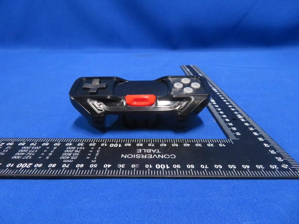
2ALS8-OP0002
Oct 25, 2023Segway Gokart Game Kit
Equipment Class
DXX - Part 15 Low Power Communication Device Transmitter