2ALZ7-3107B1709Transmitter
CCL ELECTRONICS LTD
Click to zoom
Application Details
- Equipment Class
- DXX - Part 15 Low Power Communication Device Transmitter
- Date of Grant
- Jul 11, 2020
- Application Purpose
- Original Equipment
- Date of Application
- Jul 11, 2020
- Equipment Note
- Transmitter
- Frequency Range
- 915.00000000 - 915.00000000
- Company
- CCL ELECTRONICS LTD
- Country
- Hong Kong
Documents & Files
Document Text
Text extracted from the exhibit documents filed with the FCC. Open a document above to read the original.
Users Manual
LONG RANGE WIRELESS FLOATING POOL & SPA SENSOR Model: C3107B User Manual Thank you for selecting this delicate pool & SPA sensor. Utmost care has gone into the design and manufacture of the sensor. Please read the instructions carefully according to the version you purchased and keep the manual well for future reference. OVERVIEW WIRELESS THERMO POOL SENSOR 7 4 5 3 6 8 1 2 1. LCD display 2. Thermo sensor 3. [ °C /°F ] key 4. [ CHANNEL ] slide switch - Assign the sensor to channel 1,2,3,4,5,6 or 7. 5. Battery compartment - Accommodates 2 x AA size batteries. 6. [ RESET ] key 7. Wire hole 8. Top case lock indicator GETTING STARTED 1. Turn the bottom case anti-clockwise to open. 2. Select the sensor channel. 3. Remove the battery door. 4. Insert 2 x AA size batteries into the battery compartment. Make sure you insert them the right way according to the polarity information marked on the battery compartment. AA x 2 5. Close the battery door. 6. Twist the bottom case clockwise and make sure the top and button lock indicator align to complete the setup. NOTE: Ensure the water tight O-ring is properly aligned in place to ensure water resistant. NOTE: - Do not twist the sensor cable and keep it straight. - Once the channel is assigned to a Wireless thermo sensor, you can only change it by removing the batteries or resetting the unit. - After replacing the batteries of the wireless sensor or the unit fails to receive wireless sensor signal of a specified channel, press [ SENSOR ] key on the console unit to manually receive the sensor signal again. LCD DISPLAY ON THE SENSOR Once the sensor power up, you can find the following information that show on the sensor’s LCD display. 1 3 2 1. Current channel of the sensor (e.g. switch to channel “6”) 2. Low battery indicator 3. Current Temperature reading WIRELESS SENSOR SIGNAL RECEIVING (DISPLAY CONSOLE) This pool sensor can support different 7CH console, user can base on the following step to setup the display console. 1. In normal mode, press the console [ SENSOR ] key once to start receiving the sensor signal of current on displaying channel. The signal icon will flash. For example, when CH 6 is displayed, pressing [ SENSOR ] key will start receive for CH 6 only. 2. The signal icon will flash until the reception succeeded. If no signal is received within 5 minutes the icon will disappear. The icon blinks once every time when incoming wireless sensor signal is received (every 60s) Fair wireless sensor signal Weak wireless sensor signal Bad / no wireless sensor signal 3. If the signal for Ch 1~7 has discontinued and does not recover within 15 minutes, the temperature and humidity will display “Er” for the corresponding channel. 4. If the signal does not recover within 48 hours, the “Er” display will become permanent. You need to replace the batteries of the “Er” channel’s sensors and then press [ SENSOR ] key to pair up with the sensors per each “Er” channel again. NOTE: The operation or signal icons of different display consoles may be different, please refer to the user manual of your display console for more detail. SENSOR PLACEMENT Place the sensor in the pool within 30 meters (100 feet) of the display console and avoid side wall of the pool block the sensor signal. Display console Pool sensor placement LOW BATTERY ICON If the sensor is low in battery, the low battery icon “ ” will display on the LCD of the sensor and display console. NOTE: On the display console, the low battery icon will only appear when the corresponding channel is displaying. PRECAUTIONS WHEN OPENING AND CLOSING THE SENSOR CASING Inner O-ring Outer O-ring 1. Opening the casing: - Unscrew the bottom casing carefully in direction indicated - There are 2 o-rings , one inner and one outer in blue color between the 2 casings - The outer O-ring may drop down and rest on the bottom casing. Inner O-ring Outer O-ring 2. Before closing the casing: - Ensure the unit is wiped dry completely or leave to dry to avoid trapping any moisture inside - Carefully place both O-rings back into their respective grooves, and apply water-tightness jell/grease if necessary Misplaced outer O-ring 3. Closing the casing: - Ensure the outer O-ring is not misplaced (as shown) when closing the casing - Close the casing tightly such that the 2 vertical arrows aligned vertically and pointing to each other (circled in gray) - Water droplets may condense on the LCD if moisture is trapped inside the unit. Just leave the unit open and let the droplet evaporate naturally before closing the casings IMPORTANT NOTE - Read and keep these instructions. - Do not subject the unit to excessive force, shock, dust, temperature or humidity. - Do not cover the ventilation holes with any items such as newspapers, curtains etc. - Do not clean the unit with abrasive or corrosive materials. - Do not tamper with the unit’s internal components. This invalidates the warranty. - Only use fresh batteries. Do not mix new and old batteries. - Do not dispose old batteries as unsorted municipal waste. Collection of such waste separately for special treatment is necessary. - Attention! Please dispose of used unit or batteries in an ecologically safe manner. -Technical specifications and user manual contents for this product are subject to change without notice. SPECIFICATIONS Dimensions (W x H x D)100 x 207.5 x 100 mm Main power 2 x AA size 1.5V batteries (Alkaline battery recommended) Operating temperature range -5°C ~ 60°C ( -23°F ~ 140°F ) do not recommend under freeze condition RF frequency 915 MHz for US RF Transmission interval60 seconds RF transmission range Up to 30 m (100 feet) line of sight This device complies with Part 15 of the FCC Rules. Operation is subject to the following two conditions: (1) this device may not cause harmful interference, and (2) this device must accept any interference received, including interference that may cause undesired operation. Warning: Changes or modifications to this unit not expressly approved by…
Text truncated - open the document above for the full version.
External Photos
INTERTEK TESTING SERVICE Report No.: HK18020547 Equipment Photographs (External)
ID Label/Location Info
MADE IN CHINA 2ALZ7-3107B1709 Ambient, LLC. Model No.:TX-3107 30mm
Internal Photos
INTERTEK TESTING SERVICE Report No.: HK18020547 Equipment Photographs (Internal) INTERTEK TESTING SERVICE Report No.: HK18020547 Equipment Photographs (Internal) INTERTEK TESTING SERVICE Report No.: HK18020547 Equipment Photographs (Internal)
RF Exposure Info
Analysis Report Report No.: 18020547HKG-001 The equipment under test (EUT) is a 915MHz transmitter (i.e. Pool Sensor) system. The sensor is operating at 915MHz and it sends the data to the main console (corresponding receiver unit) for measurement. The EUT is powered by 2 x AA batteries (3.0VDC). According to the KDB 447498: Based on the Maximum allowed field strength of production tolerance was 95.2 dBμV/m at 3m in frequency 915MHz, thus; It below calculated field strength according to minimum SAR exclusion threshold level as follows: The worst case of SAR Exclusion Threshold Level: = 3.0 * (min. test separation distance, mm) / sqrt(freq. in GHz) = 3.0 * 5 / sqrt (0.915) mW = 15.7 mW According to the KDB 412172 D01: EIRP = [(FS*D) ^2*1000 / 30] Calculated Field Strength for 15.7mW is 107.2dBuV/m @3m Since maximum field strength plus production tolerance < = 107.2dBuV/m @3m and antenna gain is > = 0.0dBi, it is concluded that maximum Conducted Power and Field Strength are well below the SAR Exclusion threshold level, so the EUT is considered to comply with SAR requirement without testing.
Test Report
2/F., Garment Centre, 576 Castle Peak Road, Kowloon, Hong Kong SAR, China. Telephone: (852) 2173 8888 Facsimile: (852) 2785 5487 www.intertek.com Intertek’s standard Terms and Conditions can be obtained at our website http://www.intertek.com/terms/. The test report only allows to be revised within the retention period unless further standard or the requirement was noticed. This report is for the exclusive use of Intertek's Client and is provided pursuant to the agreement between Intertek and its Client. Intertek's responsibility and liability are limited to the terms and conditions of the agreement. Intertek assumes no liability to any party, other than to the Client in accordance with the agreement, for any loss, expense or damage occasioned by the use of this report. Only the Client is authorized to permit copying or distribution of this report and then only in its entirety. Any use of the Intertek name or one of its marks for the sale or advertisement of the tested material, product or service must first be approved in writing by Intertek. The observations and test results in this report are relevant only to the sample tested. This report by itself does not imply that the material, product, or service is or has ever been under an Intertek certification program. © 2017 Intertek Page 1 of 16 TEST REPORT Report No.: 18020547HKG‐001R1 CCL Electronics Ltd. Application For Certification (Original Grant) FCC ID: 2ALZ7‐3107B1709 Transmitter This report supersedes previous report with report number 18020547HKG‐001 dated March 23, 2018. Please refer ICT‐S20‐0011 Letter issued on July 10, 2020 for amendment/ supersede notification. Prepared and Checked by: Approved by: Signed On File Wong Cheuk Ho, Herbert Lead Engineer Wong Kwok Yeung, Kenneth Senior Lead Engineer Date: July 10, 2020 TEST REPORT CCL Electronics Ltd. Intertek Report No: 18020547HKG‐001R1 Page 2 of 16 GENERAL INFORMATION Grantee: CCL Electronics Ltd. Grantee Address: Unit 1‐3, 9/F., Wang Lung Industrial Building, 11 Lung Tak Street, Tsuen Wan, N.T., Hong Kong. Contact Person: Joey Yip Tel: 2611 3000 Fax: 2611 3088 e‐mail: [email protected] Manufacturer: CCL Electronics Ltd. Manufacturer Address: Unit 1‐3, 9/F., Wang Lung Industrial Building, 11 Lung Tak Street, Tsuen Wan, N.T., Hong Kong. Brand Name: CCL Model: C3107B Additional Model: N/A Type of EUT: Transmitter Description of EUT: Transmitter Serial Number: N/A FCC ID : 2ALZ7‐3107B1709 Date of Sample Submitted: February 13, 2018 Date of Test: February 13, 2018 to March 02, 2018 Report No.: 18020547HKG‐001R1 Report Date: July 10, 2020 Environmental Conditions: Temperature: +10 to 40°C Humidity: 10 to 90% Conclusion: Test was conducted by client submitted sample. The submitted sample as received complied with the 47 CFR Part 15 Certification. TEST REPORT CCL Electronics Ltd. Intertek Report No: 18020547HKG‐001R1 Page 3 of 16 SUMMARY OF TEST RESULT Test Specification Reference Results Radiated Emission Radiated Emission on the Bandedge 15.249, 15.209 Pass Radiated Emission in Restricted Bands 15.205 Pass The equipment under test is found to be complying with the following standards: FCC Part 15, October 1, 2019 Edition Note: 1. The EUT uses a permanently attached antenna which, in accordance to section 15.203, is considered sufficient to comply with the pervisions of this section. 2. Pursuant to FCC part 15 Section 15.215(c), the 20 dB bandwidth of the emission was contained within the frequency band designated (mentioned as above) which the EUT operated. The effects, if any, from frequency sweeping, frequency hopping, other modulation techniques and frequency stability over excepted variations in temperature and supply voltage were considered. TEST REPORT CCL Electronics Ltd. Intertek Report No: 18020547HKG‐001R1 Page 4 of 16 TABLE OF CONTENTS 1.0 GENERAL DESCRIPTION ................................................................................................5 1.1 Product Description .................................................................................................5 1.2 Related Submittal(s) Grants......................................................................................5 1.3 Test Methodology....................................................................................................5 1.4 Test Facility ..............................................................................................................5 2.0 SYSTEM TEST CONFIGURATION.....................................................................................6 2.1 Justification..............................................................................................................6 2.2 EUT Exercising Software...........................................................................................6 2.3 Special Accessories...................................................................................................6 2.4 Measurement Uncertainty.......................................................................................6 2.5 Support Equipment List and Description ..................................................................6 3.0 EMISSION RESULTS.......................................................................................................7 3.1 Field Strength Calculation.........................................................................................7 3.2 Radiated Emission Configuration Photograph...........................................................8 3.3 Radiated Emission Data............................................................................................8 4.0 EQUIPMENT PHOTOGRAPHS ......................................................................................11 5.0 PRODUCT LABELLING..................................................................................................11 6.0 TECHNICAL SPECIFICATIONS .......................................................................................11 7.0 INSTRUCTION MAN…
Text truncated - open the document above for the full version.
Test Setup Photos
INTERTEK TESTING SERVICE Report No: HK18020547 Configuration Photographs Worst-Case Radiated Emissions (Front View) INTERTEK TESTING SERVICE Report No: HK18020547 Configuration Photographs Worst-Case Radiated Emissions (Rear View)
Contact Information
Applicant
Joey Yip(Sales Manager)
Technical Contact
Intertek Testing Services Hong Kong Ltd.Kenneth Wong
[email protected](852) 2173 8888
2/F., Garment Centre, · Hong Kong
Non-Technical Contact
Intertek Testing Services Hong Kong Ltd.Kenneth Wong
[email protected](852) 2173 8888
Test Firm
Intertek Testing Services Hong Kong Ltd.Billy Chow
Technical Specifications
| # | Rule Parts | Frequency Range | Power Output |
|---|---|---|---|
| 1 | 15C | 915 MHz - 915 MHz | - |
Other Applications from CCL ELECTRONICS LTD

2ALZ7-WM260107
Jan 29, 2026WiFi module
Equipment Class
DTS - Digital Transmission System
2ALZ7-3130A2104
Aug 01, 2021Wireless Weather Sensor (915MHz Transmitter)
Equipment Class
DXX - Part 15 Low Power Communication Device Transmitter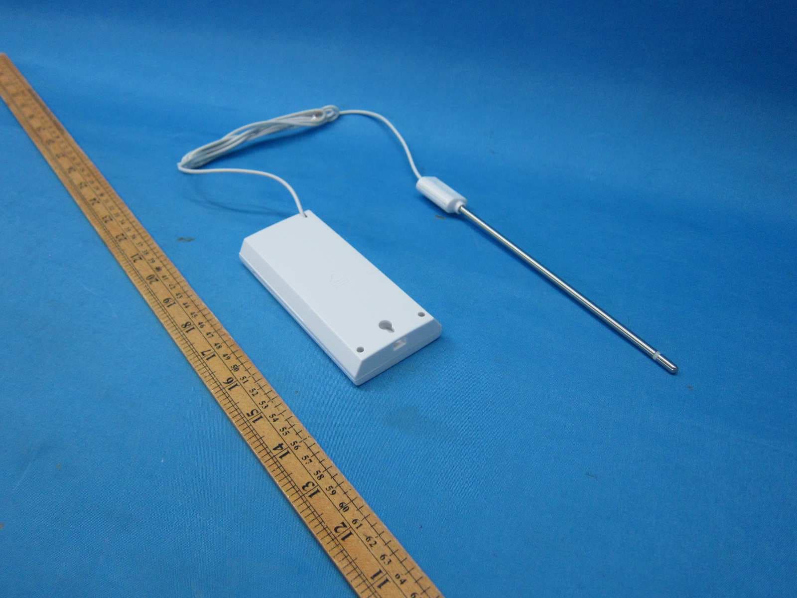
2ALZ7-3127A2102
Aug 01, 2021Wireless Weather Sensor (915MHz Transmitter)
Equipment Class
DXX - Part 15 Low Power Communication Device Transmitter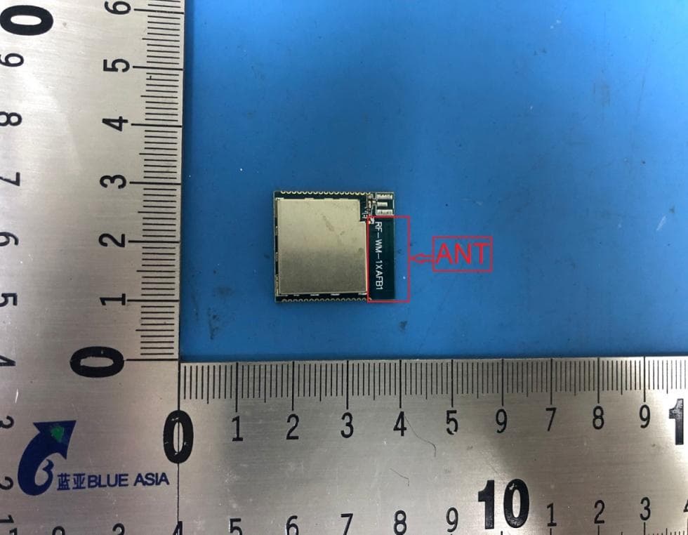
2ALZ7-11AFB2005
Jul 14, 2020WIFI MODULE
Equipment Class
DTS - Digital Transmission System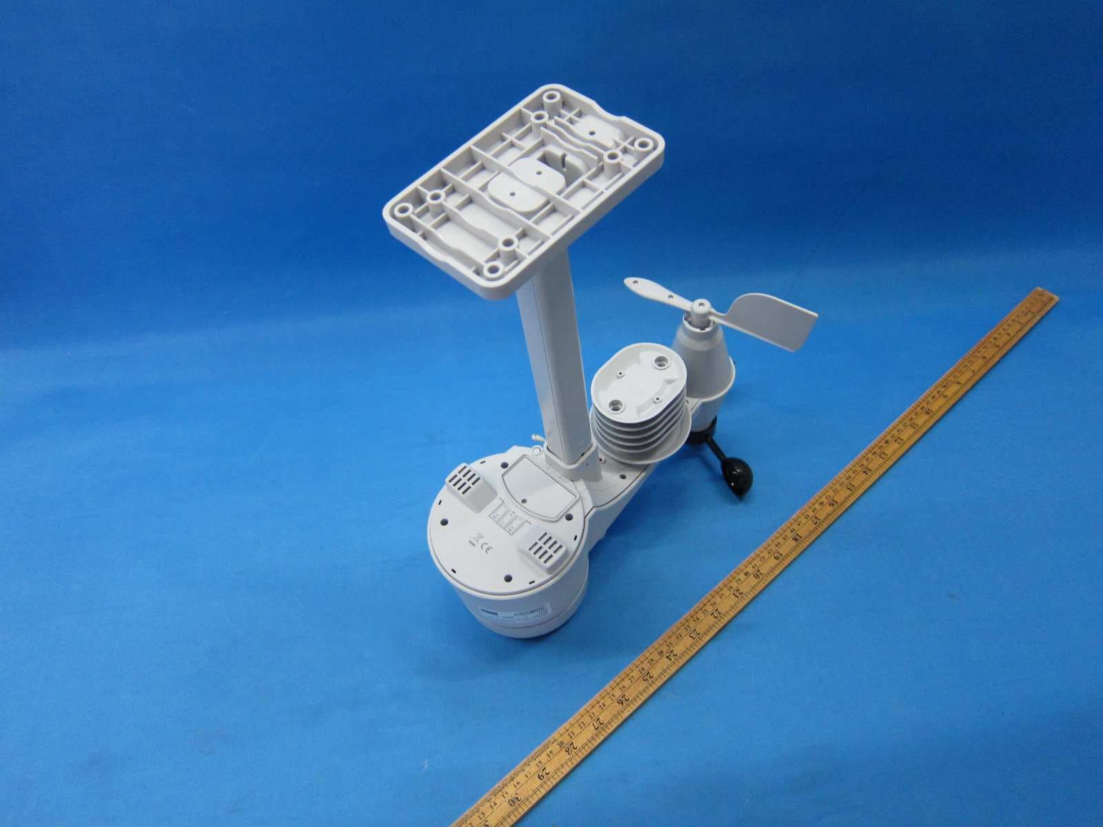
2ALZ7-3120A2004
Jul 05, 20207-In-1 Professional Sensor
Equipment Class
DXX - Part 15 Low Power Communication Device Transmitter