2ALZEL65AVCell Phone Signal Booster
Shen Zhen ANNTLENT Communication Technology co., Ltd.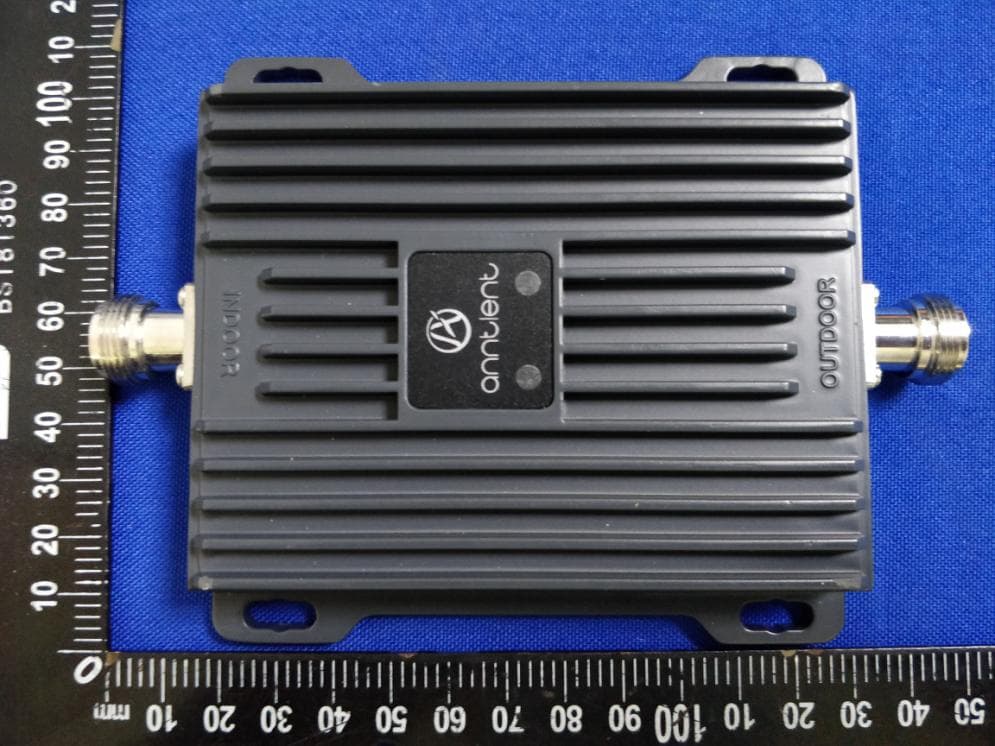
Click to zoom
Application Details
- Equipment Class
- B2W - Part 20 Wideband Consumer Booster (CMRS)
- Date of Grant
- Aug 23, 2020
- Application Purpose
- Original Equipment
- Date of Application
- Aug 23, 2020
- Equipment Note
- Cell Phone Signal Booster
- Frequency Range
- 746.00000000 - 757.00000000
- Country
- China
Documents & Files
Document Text
Text extracted from the exhibit documents filed with the FCC. Open a document above to read the original.
Users Manual
1 / 12 AN-L65AV Cell Phone Signal Booster User Manual 2 / 12 Introduction With the popularity of mobile communications, people want to make a call anytime, anywhere, so the coverage requirement of communication network is higher and higher, but the reality is not so, sometimes mobile phone signal is not very good, you want to make a smooth call, even in some places cell phone cannot dial out. in this cases, cell phone signal booster can solve this problem in a certain extent. Features ■ AGC(Automatic Gain Control): When the downlink output signal is too strong or self- oscillated, the uplink and downlink can automatically reduce the gain and reduce the interference signal ■ Self- Oscillation elimination: The system detects self- Oscillation, first reduces the link gain, then detects the loop, and finds that the self- oscillation is eliminated, the system returns to normal working state, otherwise, the power is turned off to prevent interference signal. ■ Inactivity Mode: When no user calls, the device is in standby mode, the uplink power amplifier is switched off, and the static power is decreased by 30%, so as to achieve the purpose of energy saving. SAFETY WARNINGS WARNING: This equipment should be installed and operated with minimum distance 20cm(8 inches)between the radiator& your body. FCC Cautions: Any changes or modifications not expressly approved by the party responsible for compliance could void the user’s authority to operate the equipment. Operation is subject to the following two conditions: (1) this device may not cause harmful interference, and (2) this device must accept any interference received, including interference that may cause undesired operation. This equipment has been tested and found to comply with the limits for a Class B digital device, pursuant to Part 15 of the FCC Rules. These limits are designed to provide reasonable protection against harmful interference in a residential installation. This equipment generates uses and can radiate radio frequency energy and, if not installed and used in accordance with the instructions, may cause harmful interference to radio communications. However, there is no guarantee that interference will not occur in a particular installation. If this equipment does cause harmful interference to radio or television reception, which 3 / 12 can be determined by turning the equipment off and on, the user is encouraged to try to correct the interference by one or more of the following measures: -- Reorient or relocate the receiving antenna. -- Increase the separation between the equipment and receiver. -- Connect the equipment into an outlet on a circuit different from that to which the receiver is connected. -- Consult the dealer or an experienced radio/TV technician for help This equipment complies with FCC radiation exposure limits set forth for an uncontrolled environment. End users must follow the specific operating instruction for satisfying RF exposure compliance. This transmitter must not be co-located oroperating in conjunction with any other Antenna or transmitter. SAFTY WARNING: End users must follow the specific operatinginstruction for satisfying RF exposure compliance. Do not remove the covers during working. Do not try to repair or replace any components inside of the equipment. Alteration or abuse of the equipment or other components will void this product’s warranty, and could be dangerous to the user. PACKAGE CONTENTS (1) Packages include the following: ① 1Pcs AN-L65AV Booster with N Female connectors. ② AC/DC Power Adaptor. ③ Screws Mounting Kits. ④ User manual (this document). (2) Booster interface description: ① LED light : The corresponding LED on the right is used to indicate the following different working conditions of the booster. LED Indicator Booster working conditions LED LIGHTContinuous GREEN @normal; Twinkly GREEN @input signals may be not enough; 4 / 12 Continuous YELLOW @ stronger input signals, AGC is working; Twinkly YELLOW@ self–oscillation happen ,AGC is working. Continuous RED@ power supply is shut down; Twinkly RED@ self–oscillation happen but power supply is NOT shut down. ②Power supply jack:The booster uses a power input range of DC 5-12V. ③ INDOOR and OUTDOOR port :The two ports are used to connect outdoor and indoor antennas. (3)Antennas and Cables: In order to use the Booster, you still need the corresponding indoor antenna 1pcs, outdoor antenna 1pcs, outdoor cable 1pcs and indoor cable 1pcs. Antennas and cables kitting information are as follows NameModelGain/LossPhoto Indoor Antenna Rubber Antenna PTE-RB-800-2100 3dbi @698~787MHz Ceiling AntennaPTE-CI-800-2500 3dbi @698~787MHz Indoor Panel Antenna PTE-PN-800-2500 7dbi @698~787MHz Outdoor Antenna YAgi Antenna PTE-YG-800/1900 8dbi @728-756MHz LPDA Antenna PTE-LO-700-2500 9dbi @728-756MHz Omni directional glass fiber Antenna PTE-GF-700-2500 3dbi @728-756MHz Indoor Cable20 feet 3D-FB Coaxial cable with N male connector PTE-3D-FB-5NB 2.29db @728-756MHz Outdoor Cable50 feet 3D-FB Coaxial cable with N male connector PTE-3D-FB-10NB 5.49db @698~ 787MHz 5 / 12 Notes:The above model antennas are suitable for AN-L65AV booster. Warning:Unauthorized antennas,cables and/or coupling devices are prohibited by FCC rules. Please contact FCC for details : 1-888-CALL-FCC The antenna, cables, and other accessories of the booster kits shall not be modified without the approval of the ANNTLENT company, otherwise it shall be deemed invalid. INSTALLATION INSTRUCTIONS (1)Installation of Outdoor Antenna The booster’s main function is to improve weak RF signals of an area. A simple formula: Input power+ Gain= Output power. The signal strength from the outdoor antenna directly affects the efficiency of the indoor coverage. It is very important to choose the outdoor antenna location in order to get the best signals. Testing the signal strength received from outdoor antenna mounted in site by mobile phone: Please select the top of building to install th…
Text truncated - open the document above for the full version.
Attestation Statements
Shen Zhen ANNTLENT Communication Technology co., Ltd. Aug 19, 2020 Attestation for Cell phone signal booster: FCC ID: 2ALZEL65AV Each Signal Booster certificated under FCC ID: 2ALZEL65AV is manufactured and individually tested to ensure FCC compliance: (1) Licensee consent for Fixed consumer booster has been obtained (consent be made available upon FCC/TCB request) (2) NPS and other compliance/safeguard features have been implemented (3) NPS and other compliance/safeguard features are defaulted to “ON” configuration (in operation) (4) NPS and other compliance/safeguard features cannot be field reconfigured, disabled or removed (5) This Consumer booster is not user programmable, does not need fine tuning or adjustment, does not require professional installation. (6) Future software upgrade will not cause non-compliance. Yours sincerely, Sam Sun
Cover Letter(s)
Shen Zhen ANNTLENT Communication Technology co., Ltd. Office of Engineering Technology Federal Communications Commission 7435 Oakland Mills Road Columbia, MD 21046 USA Date: 2020-08-19 Subject; Request for Long Term Confidentiality FCC ID: 2ALZEL65AV To Whom It May Concern, Pursuant to the provisions of the Commission’s rules Title 47 Sections §0.457 and §0.459, we are requesting the Commission to withhold the following attachment(s) as confidential documents from public disclosure indefinitely. These documents contain detailed system and equipment descriptions and are considered as proprietary information in operation of the equipment. The public disclosure of these documents might be harmful to our company and would give competitors an unfair advantage in the market. Schematic Diagram Block Diagram Parts List Operational Description Tune-up Procedure It is our understanding that all measurement test reports, FCC ID label format and correspondence during the certification review process cannot be granted as confidential documents and this information will be available for public review once the grant of equipment authorization is issued. Sincerely, Signature: Name: Sam Sun Title: Manager
Cover Letter(s)
Shen Zhen ANNTLENT Communication Technology co., Ltd. Room 601, Unit 1 Building 10, Haoyue Garden, Minzhi Sub-district, Longhua District, Shenzhen, China Statement Product: Cell Phone Signal Booster Model: AN-L65AV Additional Model: AN-L45AV Trademark: We hereby state that All models above are identical in interior structure, electrical circuits and components, and just model names and trademark are different for the marketing requirement. Your assistance on this matter is highly appreciated. Yours sincerely, Signature: Date: 2020/08/19 Name: Sam Sun Company Name : Shen Zhen ANNTLENT Communication Technology co., Ltd. Address: Room 601, Unit 1 Building 10, Haoyue Garden, Minzhi Sub-district, Longhua District, Shenzhen, China Tel / Fax: +8675528192218/+8675528192268 E-Mail: [email protected]
Cover Letter(s)
NameModelGain/LossPhoto Indoor Antenna Rubber Antenna PTE-RB-800-2100 3dbi @698~787MHz Ceiling AntennaPTE-CI-800-25003dbi @698~787MHz Indoor Panel Antenna PTE-PN-800-25007dbi @698~787MHz Outdoor Antenna YAgi Antenna PTE-YG-800/1900 8dbi @728-757MHz LPDA Antenna PTE-LO-700-2500 9dbi @728-757MHz Omnidirectional glass fiberAntenna PTE-GF-700-2500 3dbi @728-757MHz Indoor Cable20feet 3D-FB Coaxial cable with N male connector PTE-3D-FB-5NB2.29db @728-757MHz Outdoor Cable50feet 3D-FB Coaxial cable with N male connector PTE-3D-FB-10NB5.49db @698~ 787MHz
Cover Letter(s)
Shen Zhen ANNTLENT Communication Technology co., Ltd. Aug 19, 2020 Subject: Tuning and Adjustment of Signal booster, FCC ID: 2ALZEL65AV There are no external tuning adjustments, The amplifier is factory set not exceed maximum gains, power levels, and downlink dependent region (RSSI) set points as provided in the test results. Yours sincerely, Sam Sun
Cover Letter(s)
Shen Zhen ANNTLENT Communication Technology co., Ltd. Agent Authorization Company: Shen Zhen ANNTLENT Communication Technology co., Ltd. Address: Room 601, Unit 1 Building 10, Haoyue Garden, Minzhi Sub-district, Longhua District, Shenzhen, China Product Name: Cell Phone Signal Booster Model Number(s): AN-L65AV, AN-L45AV Product Description: Cell Phone Signal Booster We authorize MiCOM Labs Inc., 575 Boulder Court, Pleasanton, California 94566, USA, to act on our behalf on all matters concerning the certification of above named equipment. We declare that MiCOM Labs Inc. is allowed to forward all information related to the approval and certification of equipment to the regulatory agencies as required and to discuss any issues concerning the approval application. Any and all acts carried out by MiCOM Labs on our behalf shall have the same effect as acts of our own. Signature: Date: 2020-08-19 Name: Sam Sun Title: Manager Company: Shen Zhen ANNTLENT Communication Technology co., Ltd.
External Photos
Page 1 of 4 Appendix B: Photographs of EUT Product: Cell Phone Signal Booster Model: AN-L65AV External Photos Page 2 of 4 Page 3 of 4 Page 4 of 4
ID Label/Location Info
Label Artwork and Location Model: AN-L65AV, AN-L45AV Size 1: L*W=40*25mm Size 2: L*W=40*60mm Location 1 Location 2 Size 1: L*W=40*25mm Size 2 : L*W=40*60mm Location 1 Location 2 AN-L45AV AN- L45AV
Internal Photos
Page 1 of 2 Appendix B: Photographs of EUT Product: Cell Phone Signal Booster Model: AN-L65AV Internal Photos Page 2 of 2
RF Exposure Info
Maximum Permissible Exposure(MPE) Report 1. Applicable Standard FCC Part §1.1310 2. Requirements Limits For Maximum Permissible Exposure (MPE) Frequency range (MHz) Electric field strength(V/m) Magnetic field Strength(A/m) Power density (mw/cm 2 ) Averaging time (minutes) 0.3-1.34 614 1.63 *100 30 1.34-30 824/f 2.19/f *180/f 2 30 30-300 27.5 0.0173 0.2 30 300-1,500 f/1500 30 1,500-100,000 1.0 30 3. MPE Calculation Predication of MPE limit at a given distance S = Power density (In appropriate units, e.g., mW/cm 2 ) P = Power input to the antenna ( In appropriate units, e.g., mW) G = Power gain og the antenna in the direction of interest relative to an isotropic radiator, the power gain factor, Is normally numeric gain R =Distance tp the center of radiation of the antenna(In appropriate units, e.g., cm 4. Test Result Results: PASS Operation Bands Frequency (MHz) Conducted power(dBm) Cable loss (dB) Power to Antenna(mW) Antenna gain Isotropic Numeric UL698-716 707.85 19.29 5.49 23.99 9 7.94 UL776-787 782.93 17.40 5.49 15.52 9 7.94 DL728-746 739.74 6.71 2.29 2.77 7 5.01 DL746-757 748.76 8.55 2.29 4.23 7 5.01 Operation Bands Power (mW) Antenna gain(G) Measure Distance(cm) Power density (mW/cm 2) MPE limit (mW/cm 2) UL698-716 23.99 7.94 20 0.038 0.465 UL776-787 15.52 7.94 20 0.025 0.517 DL728-746 2.77 5.01 20 0.003 0.485 DL746-757 4.23 5.01 20 0.004 0.497
Test Report
Hotline: 400-6611-140 Tel: 86-755-27673339 Fax: 86-755-27673332 http://www.tct-lab.com TEST REPORT FCC ID: 2ALZEL65AV Product: Cell Phone Signal Booster Model No.: AN-L65AV Additional Model No.: AN-L45AV Trade Mark: Report No.: TCT200623E003 Issued Date: Aug. 12, 2020 Issued for: Shen Zhen ANNTLENT Communication Technology co., Ltd. Room 601, Unit 1 Building 10, Haoyue Garden, Minzhi Sub-district, Longhua District, Shenzhen, China Issued By: Shenzhen Tongce Testing Lab. 1B/F., Building 1, Yibaolai Industrial Park, Qiaotou, Fuyong, Baoan District, Shenzhen, Guangdong, China TEL: +86-755-27673339 FAX: +86-755-27673332 Note: This report shall not be reproduced except in full, without the written approval of Shenzhen Tongce Testing Lab. This document may be altered or revised by Shenzhen Tongce Testing Lab. personnel only, and shall be noted in the revision section of the document. The test results in the report only apply to the tested sample. Report No.: TCT200623E003 Page 2 of 110 Hotline: 400-6611-140 Tel: 86-755-27673339 Fax: 86-755-27673332 http://www.tct-lab.com TABLE OF CONTENTS 1. Test Certification ..................................................................................... 3 2. Test Result Summary .............................................................................. 4 3. EUT Description ....................................................................................... 5 4. General Information ................................................................................. 6 4.1. Test environment ................................................................................................... 6 4.2. Description of Support Units ................................................................................ 6 5. Facilities and Accreditations .................................................................. 7 5.1. Facilities ................................................................................................................. 7 5.2. Location ................................................................................................................. 7 5.3. Measurement Uncertainty ..................................................................................... 7 6. Test Results and Measurement Data ..................................................... 8 6.1. Authorized Frequency Band Verification ............................................................ 8 6.2. Maximum Power .................................................................................................. 12 6.3. Intermodulation Product ..................................................................................... 22 6.4. Out of Band Emission ......................................................................................... 28 6.5. Conducted Spurious Emission .......................................................................... 54 6.6. Noise Limits ......................................................................................................... 62 6.7. Uplink Inactivity ................................................................................................... 68 6.8. Variable Booster Gain ......................................................................................... 71 6.9. Occupied Bandwidth ........................................................................................... 75 6.10.Oscillation Detection and Mitigation ................................................................. 89 7. Radiation Spurious Emission ............................................................. 100 Appendix A: Photographs of Test Setup Appendix B: Photographs of EUT Report No.: TCT200623E003 Page 3 of 110 Hotline: 400-6611-140 Tel: 86-755-27673339 Fax: 86-755-27673332 http://www.tct-lab.com 1. Test Certification Product: Cell Phone Signal Booster Model No.: AN-L65AV Additional Model: AN-L45AV Trade Mark: Applicant: Shen Zhen ANNTLENT Communication Technology co., Ltd. Address: Room 601, Unit 1 Building 10, Haoyue Garden, Minzhi Sub-district, Longhua District, Shenzhen, China Manufacturer: Shen Zhen ANNTLENT Communication Technology co., Ltd. Address: Room 601, Unit 1 Building 10, Haoyue Garden, Minzhi Sub-district, Longhua District, Shenzhen, China Date of Test: Jun. 24, 2020 – Aug. 11, 2020 Applicable Standards: FCC CFR Title 47 Part 20.21 The above equipment has been tested by Shenzhen Tongce Testing Lab. and found compliance with the requirements set forth in the technical standards mentioned above. The results of testing in this report apply only to the product/system, which was tested. Other similar equipment will not necessarily produce the same results due to production tolerance and measurement uncertainties. Tested By: Date: Aug. 11, 2020 Rleo Reviewed By: Date: Aug. 12, 2020 Beryl Zhao Approved By: Date: Aug. 12, 2020 Tomsin Report No.: TCT200623E003 Page 4 of 110 Hotline: 400-6611-140 Tel: 86-755-27673339 Fax: 86-755-27673332 http://www.tct-lab.com 2. Test Result Summary Requirement CFR 47 Section Result Authorized Frequency Band Verification Test §20.21(e)(3) PASS Maximum Power Measurement Procedure §2.1046/20.21(e)(8)(i)(D) PASS Maximum Booster Gain Computation §20.21(e)(8)(i)(B) PASS Intermodulation Product §20.21(e)(8)(i)(F) PASS Out of Band Emissions §20.21(e)(8)(i)(E) PASS Conducted Spurious Emission §2.1051/§27 PASS Noise Limit Procedure Variable Noise Variable Noise Timing §20.21(e)(8)(i)(A)(2)(i) §20.21(e)(8)(i)(A)(1) §20.21(e)(8)(i)(H) PASS Uplink inactivity §20.21(e)(8)(i)(I) PASS Variable Booster Gain Variable Uplink Gain Timing §20.21(e)(8)(i)(C) (1), (2)(i) §20.21(e)(8)(i)(H) PASS Occupied Band Width §2.1049/§27 PASS Anti-Oscillation §20.21(e)(8)(ii)(A) PASS Radiated Spurious Emission §2.1053/§27 PASS Spectrum Block Filter N/A N/A Note: 1. PASS: Test item meets the requirement. 2. Fail: Test item does not meet the requirement. 3. N/A: Test case does not apply to the test object. 4. The test result judgment …
Text truncated - open the document above for the full version.
Test Report
Report No.: TCT200623E003 Page 61 of 110 Hotline: 400-6611-140 Tel: 86-755-27673339 Fax: 86-755-27673332 http://www.tct-lab.com Report No.: TCT200623E003 Page 62 of 110 Hotline: 400-6611-140 Tel: 86-755-27673339 Fax: 86-755-27673332 http://www.tct-lab.com 6.6. Noise Limits 6.6.1. Test Specification Test Requirement: FCC Part20 Section 20.21(e)(8)(i)(A); 20.21(e)(8)(i)(H) Test Method: KDB D03 signal Booster Measurements v04r04 Limit: not exceed −103 dBm/MHz—RSSI. not exceed −102.5 dBm/MHz + 20 log (F), where Frequency is the uplink mid-band frequency of the supported spectrum bands in MHz. Test Setup: Test Procedure: a) Connect the EUT to the test equipment as shown in Figure 3. Begin with the uplink output (donor) port connected to the spectrum analyzer. When measuring downlink noise, connect the downlink output (server) port to the spectrum analyzer. b) Set the spectrum analyzer RBW to 1 MHz with the VBW ≥ 3 . RBW. c) Select the power averaging (rms) detector and trace average over at least 100 traces. d) Set the center frequency of the spectrum analyzer to the center of the CMRS band under test with the span ≥ 2 . the CMRS band. e) Measure the maximum transmitter noise power level. f) Save the spectrum analyzer Test Plots as necessary for inclusion in the final test report. g) Repeat 7.7b) to 7.7f) for all operational uplink and downlink bands. h) Connect the EUT to the test equipment as shown in Figure 4 for uplink noise power measurement in the presence a downlink signal. Affirm the coupled path of the RF coupler is connected to the spectrum analyzer. i) Configure the signal generator for AWGN operation with a 99% OBW of 4.1 MHz. j) Set the spectrum analyzer RBW for 1 MHz, VBW ≥ 3 . RBW, with a power averaging (rms) detector with at least 100 trace averages. k) Set the center frequency of the spectrum analyzer to the center of the CMRS band under test, with the span ≥ 2 the CMRS Report No.: TCT200623E003 Page 63 of 110 Hotline: 400-6611-140 Tel: 86-755-27673339 Fax: 86-755-27673332 http://www.tct-lab.com band. This shall include all spectrum blocks in the particular CMRS band under test (see Appendix A). l) For uplink noise measurements, set the spectrum analyzer center frequency for the uplink band under test, and tune the signal generator to the center of the paired downlink band. m) Measure the maximum transmitter noise power level while varying the downlink signal generator output level from −90 dBm to −20 dBm, as measured at the input port (i.e., downlink signal level at the booster donor port node of Figure 4), in 1 dB steps inside the RSSI-dependent region, and in 10 dB steps outside the RSSI-dependent region. Report the six values closest to the limit, with at least two points within the RSSI-dependent region of the limit. See Appendix D for noise limits graphs. n) Repeat 7.7.1h) through 7.7.1m) for all operational uplink bands. Variable uplink noise timing Variable uplink noise timing is to be measured as follows, using the test setup shown in Figure 4. a) Set the spectrum analyzer to the uplink frequency to be measured. b) Set the span to 0 Hz, with a sweep time of 10 seconds. c) Set the power level of signal generator to the lowest level of the RSSI-dependent noise [see 7.7.1m)]. d) Select MAX HOLD and increase the power level of signal generator by 10 dB for mobile boosters, and 20 dB for fixed boosters. e) Confirm that the uplink noise decreases to the specified level within 1 second for mobile devices, and within 3 seconds for fixed devices.12 f) Repeat 7.7.2a) to 7.7.2e) for all operational uplink bands. g) Include Test Plotss and summary table in test report. Test Result: PASS 6.6.2. Test Instruments Equipment Manufacturer Model Serial Number Calibration Date Calibration Due Signal Generator Agilent E4421B GB39340839 Jul. 28, 2020 Jul. 27, 2021 Signal Generator Agilent N5182A MY47070282 Sep. 12, 2019 Sep. 11, 2020 Spectrum Analyzer Agilent N9020A MY49100619 Sep. 12, 2019 Sep. 11, 2020 RF Combiner SUNVNDN SUD-CS 0800 16230009 Sep. 12, 2019 Sep. 11, 2020 Attenuator 50FP-006-H3 JFW 907763 Sep. 12, 2019 Sep. 11, 2020 Note: The calibration interval of the above test instruments is 12 months and the calibrations are traceable to international system unit (SI). Report No.: TCT200623E003 Page 64 of 110 Hotline: 400-6611-140 Tel: 86-755-27673339 Fax: 86-755-27673332 http://www.tct-lab.com 6.6.3. Test Data Max Noise Power Frequency Band (MHz) Measured dBm/MHz Limit dBm/MHz Result (dB) Band12 Uplink -49.74 -45.51 PASS Band13 Uplink -50.88 -44.64 PASS Band12 Downlink -48.24 -45.51 PASS Band13 Downlink -48.33 -44.64 PASS Note: Fixed booster maximum noise power shall not exceed −102.5 dBm/MHz + 20 log (F), where Frequency is the uplink mid-band frequency of the supported spectrum bands in MHz. Variable Uplink Noise Operation Bands RSSI dBm Measured dBm/MHz Limit dBm/MHz Results Band12 -58 -51.24 -45 PASS -55 -53.49 -48 PASS -48 -61.59 -55 PASS -45 -63.90 -58 PASS -37 -66.74 -66 PASS -36 -67.82 -67 PASS Band13 -57 -53.71 -46 PASS -52 -58.47 -51 PASS -50 -60.25 -53 PASS -44 -64.71 -59 PASS -38 -67.73 -65 PASS -36 -68.60 -67 PASS Note: According to the KDB 935210 D03 Signal Booster Measurements v04r04 APPENDIX D,when outside of RSSI Dependent limit (20.21.e.8.1.A.1),fixed booster maximum noise power shall not exceed −102.5 dBm/MHz + 20 log (F).RSSI limit not exceed −103 dBm/MHz-RSSI. Variable Uplink Noise Timing Operation Bands Measured Sec Limit Sec Results Band12 0.262 3 PASS Band13 0.064 3 PASS Report No.: TCT200623E003 Page 65 of 110 Hotline: 400-6611-140 Tel: 86-755-27673339 Fax: 86-755-27673332 http://www.tct-lab.com Band12 Uplink Noise Downlink Noise Test Plots Report No.: TCT200623E003 Page 66 of 110 Hotline: 400-6611-140 Tel: 86-755-27673339 Fax: 86-755-27673332 http://www.tct-lab.com Band13 Uplink Noise Downlink Noise Report No.: TCT200623E003 Page 67 of 110 Hotline: 400-6611-140 Tel: 86-755-27673339 Fax: 86-755-27673332 http://www.tct-lab.com Band12 Band13 Variable Noise …
Text truncated - open the document above for the full version.
Test Setup Photos
Page 1 of 2 Appendix A: Photographs of Test Setup Product: Cell Phone Signal Booster Model: AN-L65AV Page 2 of 2
Contact Information
Applicant
Sam Sun
Technical Contact
Test Firm
SHENZHEN TONGCE TESTING LABBeryl Zhao
[email protected]+8675527208735
Technical Specifications
| # | Rule Parts | Frequency Range | Power Output | Emission |
|---|---|---|---|---|
| 8 | 27 | 746 MHz - 757 MHz | 4.00 mW | W7D |
Other Applications from Shen Zhen ANNTLENT Communication Technology co., Ltd.
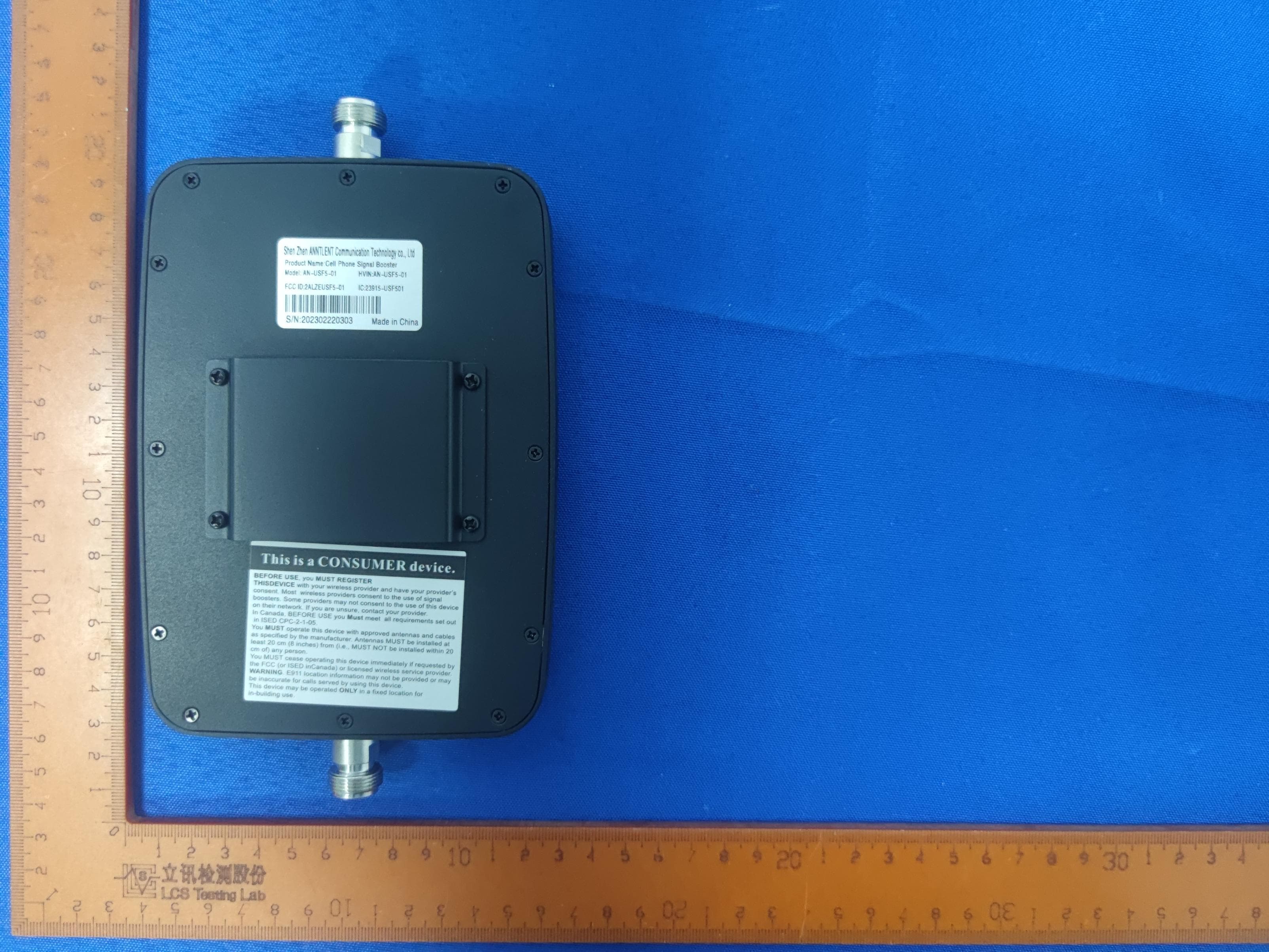
2ALZEUSF5-01
May 16, 2023Cell Phone Signal Booster
Equipment Class
B2W - Part 20 Wideband Consumer Booster (CMRS)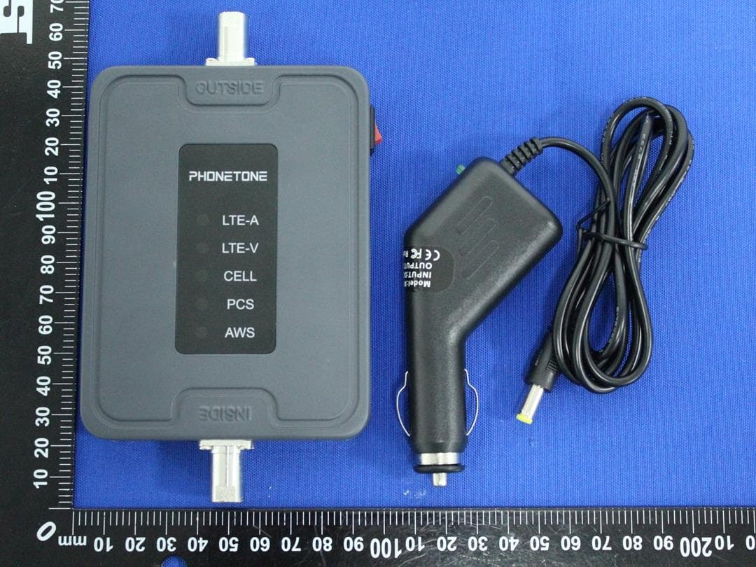
2ALZECPAL50-01
Apr 03, 2023Cell Phone Signal Booster
Equipment Class
B2W - Part 20 Wideband Consumer Booster (CMRS)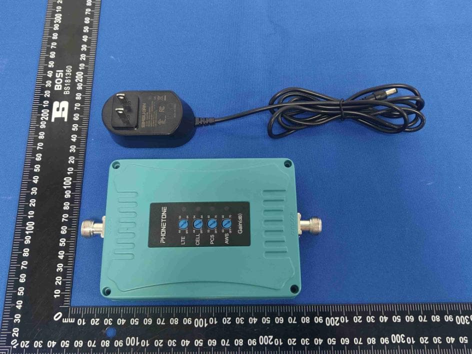
2ALZECPAL70-01
Apr 02, 2023Cell Phone Signal Booster
Equipment Class
B2W - Part 20 Wideband Consumer Booster (CMRS)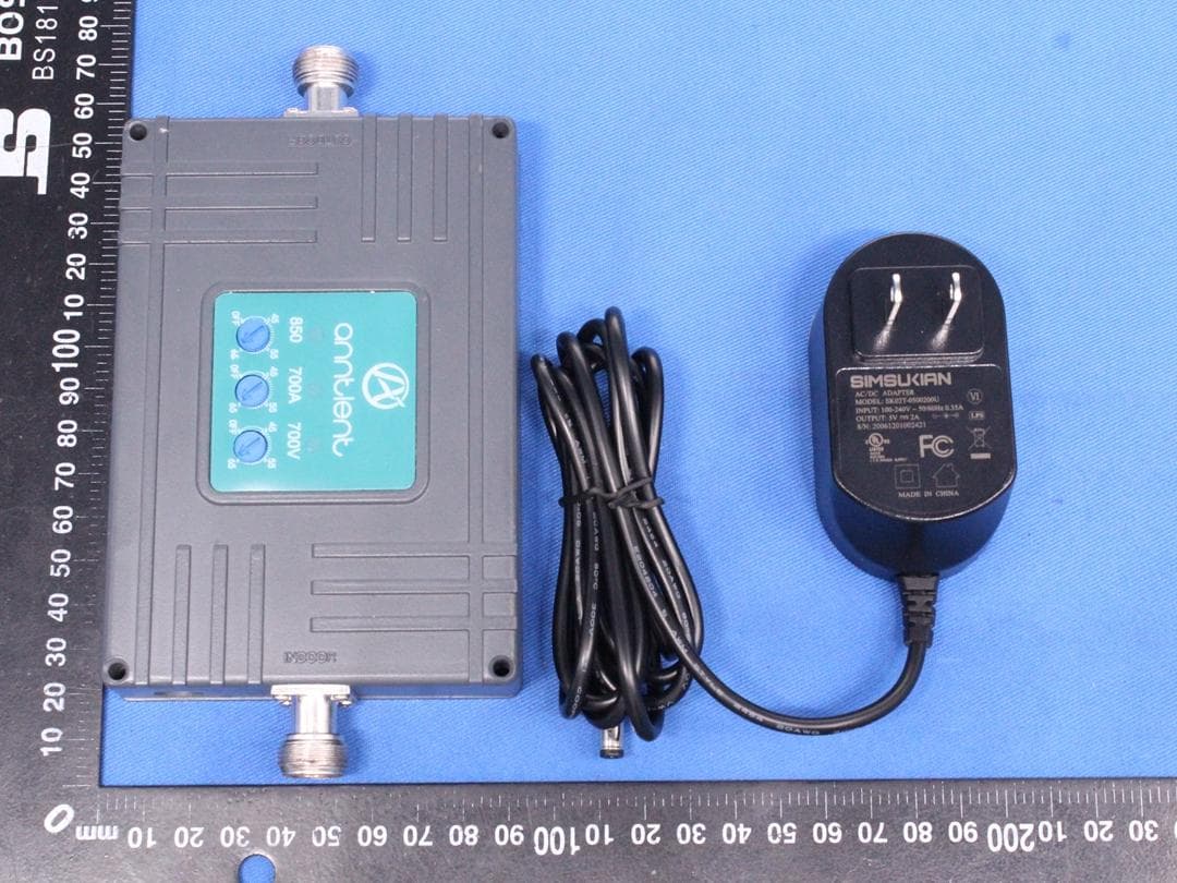
2ALZECL70AV
Nov 17, 2020Cell Phone Signal Booster
Equipment Class
B2W - Part 20 Wideband Consumer Booster (CMRS)
2ALZEAN-L70V
Nov 05, 2020Cell Phone Signal Booster
Equipment Class
B2W - Part 20 Wideband Consumer Booster (CMRS)