2AMRO-HLCRIO204Aivo connect
iOttie, Inc.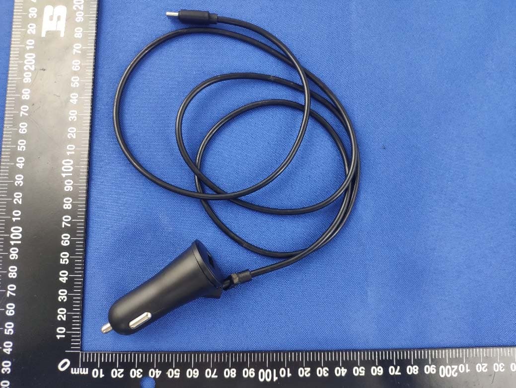
Click to zoom
Application Details
- Equipment Class
- DTS - Digital Transmission System
- Date of Grant
- Jul 20, 2020
- Application Purpose
- Original Equipment
- Date of Application
- Jul 20, 2020
- Equipment Note
- Aivo connect
- Frequency Range
- 2402.00000000 - 2480.00000000
- Company
- iOttie, Inc.
- Country
- United States
Documents & Files
Document Text
Text extracted from the exhibit documents filed with the FCC. Open a document above to read the original.
Users Manual
Aivo CONNECT With Alexa Built-in Dashboard Mount User Manual Please follow these steps in the order below to set up your device properly! Download iOttie Connect & Amazon Alexa apps Product Information What’s in the Box? Product Specifications Product Setup Assembly & Installation Using the Automatic Mounting System Qi Alignment Guide The Alexa User Experience Welcome to Alexa Pairing & Connecting a Device App Settings & Management Using Alexa Things to Try with Alexa 01 02 03 04 Download the iOttie Connect & Amazon Alexa apps 01Index Download the iOttie Connect app and Amazon Alexa app from the Apple App Store or the Google Play Store on your smartphone. Amazon Alexa app will run in the background to receive voice-activated commands. Once logged into the Amazon Alexa app, you can set Music, Navigation and other preferences to use your favorite Apps. The iOttie Connect app ensures you have the latest device firmware installed for optimal performance and device management. Follow the instructions in the app and update your device firmware. ! Make sure you are using a reliable Wi-Fi or Cellular Data Connection and Power Source. English For an optimal charging experience, please follow the detailed instructions in this manual when using the Aivo Connect. Device Compatibility Please make sure your device is Qi Wireless compatible. Compatible devices include: Apple iPhone 11 Pro Max, 11 Pro, 11, XS Max, XS, XR, X, 8 Plus, 8, Qi-Wireless enabled Airpods and compatible Airpods cases Samsung Galaxy S20 Ultra, S20+, S20, Z Flip, Fold, Note10+, Note10, S10, S10e, S10+, Note9, S9, S9+, Note8, S8, S8+, S7 edge, S7, S6 edge+, Note5, S6 edge and S6 Google Pixel 4, 3 ! Please only use the included cable and power adapter. ! Third party components may negatively impact wireless charging performance. Critical Information 02 Product Information What’s in the Box? Mounting at a perpendicular angle to the mount works best within the proximity sensor. If mounting at an angle, phone will need to be closer to sensor for arms to open. Twist Locking Base (2EA) Dual Car Charger with USB-C Cable (3ft) & USB-A port Infrared Proximity Sensor Rubber Pads 10W-7.5W Wireless Fast Charging Built Into the Cradle Wireless Charging LED Phone Release Buttons Rotating Hinge for 90 Degree turning for portrait or landscape mode USB-C Port Invoke Alexa Button 3 Microphones for seamless communication with Alexa Mute/Unmute Button Alexa LED Ring Product Specifications Assembly & InstallationAivo Connect Mount Car Charger Specifications Safety Information ITEMSPECIFICATION INPUT9V 1.67A, 5V 2A CHARGING PORTUSB-C DEPTH2.68” WIDTH3.15” HEIGHT4.61” WEIGHT6.17 oz INPUTOUTPUT 12V - 24V USB-A 5V - 2.1A USB-C 5V 3A, 9V 2A, 12V 1.5A 03 Product Setup 1. Select desired mounting location on the dashboard and clean the surface prior to installation. 2. Remove adhesive cover from bottom of twist-locking base. With the arrow facing the driver, place it in the desired mounting area. *Press and hold firmly for 30 seconds to securely adhere. 3. Connect the Aivo Connect to twist-locking base, with a 1/4 clockwise turn to lock into place. 4. Connect power cord to back of Aivo Connect and plug charger into car’s power source. ! Always be safe, do not set up this device while driving. ! Android Phones: Setup smart unlock on your device. Please add a trusted device in settings. Certain features only work when smart unlock is enabled. ! iPhone iOS & other Face ID Users: Do not use while driving! Using the Automatic Mounting System Mounting and Charging Releasing Device 1. Side arms on mount automatically open via silent step motor when phone is detected in front of Proximity Sensor on mount. 2. Once phone is placed in mount, arms will automatically close after one second. Qi wireless charging will start immediately. 3. Buttons behind cradle arms on both sides of device can open and close the arms. One or both buttons can be pressed. Qi Alignment Guide The Qi Receiver Coil is generally located in the center area of the phone. Check with your phone’s manufactur- er for specific Qi coil location. Below are some examples for commonly used phones. Aivo Connect Aivo Connect iPhone 11 Samsung Galaxy S20 Samsung Galaxy S20+ Samsung Galaxy S20 Ultra iPhone 11 Pro iPhone 11 Pro Max ! The Aivo Connect is powered via a USB-C cable and coin cell phone battery. There is no on/off switch on the device. Once plugged in, the device will remain on unless the vehicle shuts off power when in parking mode. ! Backup battery will continue to operate the Aivo Connect cradle arms (open & close) after power has been disconnected or turned off. ! CAUTION: If device flashes red a foreign object is detected and device must be removed to prevent overheating. ! The Qi coil on the mount is located in the center, in between the arms and around the Infrared Proximity Sensor 04 Explore New Roads with Alexa. You can talk to Alexa on your Aivo Connect mount. With Alexa, you can ask to get directions, play music, place calls, listen to audiobooks, hear the news, check the weather, control smart home devices, and many more--all while you keep your hands on the wheel and eyes on the road. The Aivo Connect mount supports access to tens of thousands of Alexa skills from within your vehicle. For an optimal experience, please follow the detailed instructions for Alexa setup found in the manual or the iOttie Connect app. The Alexa user Experience Welcome to Alexa. Invoke Alexa ButtonMute/Unmute Button Alexa LED Ring Indicates interaction with Alexa Microphones (x3) Outside noise reduction allows for seamless communication with Alexa Alexa LED Indicators. Solid WhitePowering On Flashing OrangeSearching Device Solid OrangeDevice not found Flashing Cyan(Flash 3x) Device is connected Solid CyanWake Word Activated Alternating Dark Blue & CyanThinking Flashing Red Device Not Connected Solid RedMute No LightNo interaction in progress • Some Alexa Skills may require an Amazon Prime membership. • Make sure …
Text truncated - open the document above for the full version.
External Photos
Annex No.: BL-SZ2060184-AW 1 / 4 EUT EXTERNAL PHOTOS FRONT VIEW OF EUT REAR VIEW OF EUT Annex No.: BL-SZ2060184-AW 2 / 4 LEFT SIDE VIEW OF EUT RIGHT SIDE OF EUT Annex No.: BL-SZ2060184-AW 3 / 4 TOP VIEW OF EUT BOTTOM VIEW OF EUT Annex No.: BL-SZ2060184-AW 4 / 4 Accessory-Car Charger
Internal Photos
Annex No.: BL-SZ2060184-AI 1 / 5 EUT INTERNAL PHOTOS EUT UNCOVER VIEW EUT UNCOVER VIEW Annex No.: BL-SZ2060184-AI 2 / 5 EUT UNCOVER VIEW EUT UNCOVER VIEW Coil Antenna Annex No.: BL-SZ2060184-AI 3 / 5 MAIN BOARD TOP VIEW MAIN BOARD REAR VIEW PIFA Antenna RF Chip Annex No.: BL-SZ2060184-AI 4 / 5 SECONDARY BOARD TOP VIEW SECONDARY BOARD REAR VIEW Annex No.: BL-SZ2060184-AI 5 / 5 Battery Photo c
Operational Description
iOttie,Inc DeclarationconcerningAntennaSpecification Itisherebydeclaredthattheproduct ModelNo.:HLCRIO204 FCCID:2AMRO-HLCRIO204 fulfillstherequirementinFCCtestrelatingtotheantennatype. ThedevicespecifiedaboveconfirmstotheFCCrecommendationsfor internal antennatype(s) describedbelow: BT&BLE: ModelNo.ofantenna: N/A Typeofantenna: PIFAAntenna Gainoftheantenna:1.47dBi Frequencyrange:2402-2480MHz DCD: ModelNo.ofantenna: N/A Typeofantenna: CoilAntenna Gainoftheantenna:1.47dBi Frequencyrange:110-205KHz Themountingoftheantennaisfixedtotheradiomoduleandnootherantennashouldbeused. Companyname: iOttie,Inc Address: 20W,37thStreet,6thFL.NewYork,NY City:NewYork ZIP/Postalcode: 10018 Country: UnitedStates Place: NewYorkDate:2020-07-20 Signature: version01
RF Exposure Info
RF Exposure Evaluation for FCC ID: 2AMRO- HLCRIO204 Refer user manual this device is a Aivo Connect, and this device was designed used in Mobile devices that the minimum distance between human’s body is 20cm. Based on the 47CFR 2.1091, this device belongs to Mobile device. The definition of the category as following: Mobile Derives: CFR Title 47 §2.1091(b) (b) For purposes of this section, a mobile device is defined as a transmitting device designed to be used in other than fixed locations and to generally be used in such a way that a separation distance of at least 20 centimeters is normally maintained between the transmitter’s radiating structure(s) and the body of the user or nearby persons. FCC KDB 447498 D01 General RF Exposure Guidance v06 Limit Devices operating in standalone mobile exposure conditions may contain a single transmitter or multiple transmitters that do not transmit simultaneously. A minimum test separation distance ≥ 20 cm is required between the antenna and radiating structures of the device and nearby persons to apply mobile device exposure limits. The distance must be fully supported by the operating and installation configurations of the transmitter and its antenna(s), according to the source-based time-averaged maximum power requirements of § 2.1091(d)(2). In cases where cable losses or other attenuations are applied to determine compliance, the most conservative operating configurations and exposure conditions must be evaluated. The minimum test separation distance required for a device to comply with mobile exposure conditions must be clearly identified in the installation and operating instructions, for all installation and exposure conditions, to enable users and installers to comply with RF exposure requirements. For mobile devices that have the potential to operate in portable device exposure conditions, similar to the configurations described in § 2.1091(d)(4), a KDB inquiry is required to determine the SAR test requirements for demonstrating compliance. When the categorical exclusion provision of § 2.1091(c) applies, the minimum test separation distance may be estimated, when applicable, by simple calculations according to plane-wave equivalent conditions, to ensure the transmitter and its antenna(s) can operate in manners that meet or exceed the estimated distance. The source-based time-averaged maximum radiated power, according to the maximum antenna gain, must be applied to calculate the field strength and power density required to establish the minimum test separation distance. When the estimated test separation distance becomes overly conservative and does not support compliance, MPE measurement or computational modeling may be used to determine the required minimum separation distance. According to FCC Part 1.1307, systems operating under the provisions of this section shall be operated in a manner the ensures that the public is not exposed to radio frequency energy level in excess of the commission’s guidelines. Limits for General Population/ Uncontrolled Exposure Frequency Range (MHz) Electric Field Strength(E)(V/m) Magnetic Field Strength (H)(A/m) Power Density (S)(mW/cm 2 ) 0.3-1.34 614 1.63 (100)* 1.34-30 824/f 2.19/f (180/f2)* 30-300 27.5 0.073 0.2 300-1500 f/1500 1500-100,000 1.0 MPE calculation formula Where: S = power density P = output power (mW) G = power gain of the antenna in the direction of interest relative to an isotropic radiator R = Separation distance between radiator and human body (cm) Test data Bluetooth Mode BR+EDR BLE GFSK ∏/4-DQPSK 8-DPSK GFSK Peak Power (dBm) 7.28 4.59 4.97 7.19 Note: This report listed the worst case peak power value, please refer to RF test report for more details. Turn-up power Mode Range (dBm) Bluetooth 2.50-7.50 Test result Evolution mode Maximum peak output power (dBm) Antenna Gain (typical) (dBi): Total Power (mw) Distance (cm) Limit of Power Density (mW/cm²) Power Density (mW/cm²) Verdict Bluetooth 7.50 1.47 7.89 20 1 0.0016 Pass Note: 1. The Aivo Connect work frequency range used is 2400 MHz ~ 2483.5 MHz, the result close to the limit by the above formula. 2. More power list please refer to RF test report. Conclusion: RF exposure Evaluation Results: Compliance
Test Report
Report No.: BL-SZ2060184-602 2 / 50 Revision History Version Issue Date Revisions Content Rev. 01 Jul. 17, 2020 Initial Issue TABLE OF CONTENTS 1 ADMINISTRATIVE DATA (GENERAL INFORMATION) .......................................................................... 5 1.1 Identification of the Testing Laboratory ....................................................................................... 5 1.2 Identification of the Responsible Testing Location ...................................................................... 5 1.3 Laboratory Condition ................................................................................................................... 5 1.4 Announce .................................................................................................................................... 5 2 PRODUCT INFORMATION ...................................................................................................................... 6 2.1 Applicant Information ................................................................................................................... 6 2.2 Manufacturer Information ............................................................................................................ 6 2.3 Factory Information ..................................................................................................................... 6 2.4 General Description for Equipment under Test (EUT) ................................................................ 6 2.5 Technical Information .................................................................................................................. 7 2.6 Additional Instructions ................................................................................................................. 8 3 SUMMARY OF TEST RESULTS .............................................................................................................. 9 3.1 Test Standards ............................................................................................................................ 9 3.2 Verdict ......................................................................................................................................... 9 4 GENERAL TEST CONFIGURATIONS ................................................................................................... 10 4.1 Test Environments .................................................................................................................... 10 4.2 Test Equipment List ................................................................................................................... 10 4.3 Measurement Uncertainty ......................................................................................................... 11 4.4 Description of Test Setup .......................................................................................................... 12 4.4.1 For Antenna Port Test ............................................................................................................... 12 4.4.2 For AC Power Supply Port Test ................................................................................................ 12 4.4.3 For Radiated Test (Below 30 MHz) ........................................................................................... 13 4.4.4 For Radiated Test (30 MHz-1 GHz) .......................................................................................... 13 4.4.5 For Radiated Test (Above 1 GHz) ............................................................................................. 14 4.5 Measurement Results Explanation Example ............................................................................. 15 4.5.1 For conducted test items: .......................................................................................................... 15 Report No.: BL-SZ2060184-602 3 / 50 4.5.2 For radiated band edges and spurious emission test: ............................................................... 15 5 TEST ITEMS ........................................................................................................................................... 16 5.1 Antenna Requirements .............................................................................................................. 16 5.1.1 Relevant Standards ................................................................................................................... 16 5.1.2 Antenna Anti-Replacement Construction .................................................................................. 16 5.1.3 Antenna Gain ............................................................................................................................ 16 5.2 Output Power ............................................................................................................................ 17 5.2.1 Test Limit ................................................................................................................................... 17 5.2.2 Test Setup ................................................................................................................................. 17 5.2.3 Test Procedure .......................................................................................................................... 17 5.2.4 Test Result ................................................................................................................................ 18 5.3 Occupied Bandwidth ................................................................................................................. 19 5.3.1 Limit ........................................................................................................................................... 19 5.3.2 Test Setup ................................................................................................................................. 19 5.3.3 Test Procedure ..................................…
Text truncated - open the document above for the full version.
Test Setup Photos
Annex No.: BL-SZ2060184-AR 1 / 4 TEST SETUP PHOTOS 1 Radiated Test Photo Below 30MHz Close-up Annex No.: BL-SZ2060184-AR 2 / 4 30MHz-1GHz Close-up Annex No.: BL-SZ2060184-AR 3 / 4 Above 1GHz Close-up Annex No.: BL-SZ2060184-AR 4 / 4 2 Conducted Test Photo Conducted Test-BT3.0 Conducted Test-BLE
Contact Information
Applicant
caleb cho
Test Firm
Shenzhen BALUN Technology Co., Ltd.Hanson Lin
[email protected]86-755-66833830
Technical Specifications
| # | Rule Parts | Frequency Range | Power Output |
|---|---|---|---|
| 1 | 15C | 2.40 GHz - 2.48 GHz | 5.24 mW |
Other Applications from iOttie, Inc.
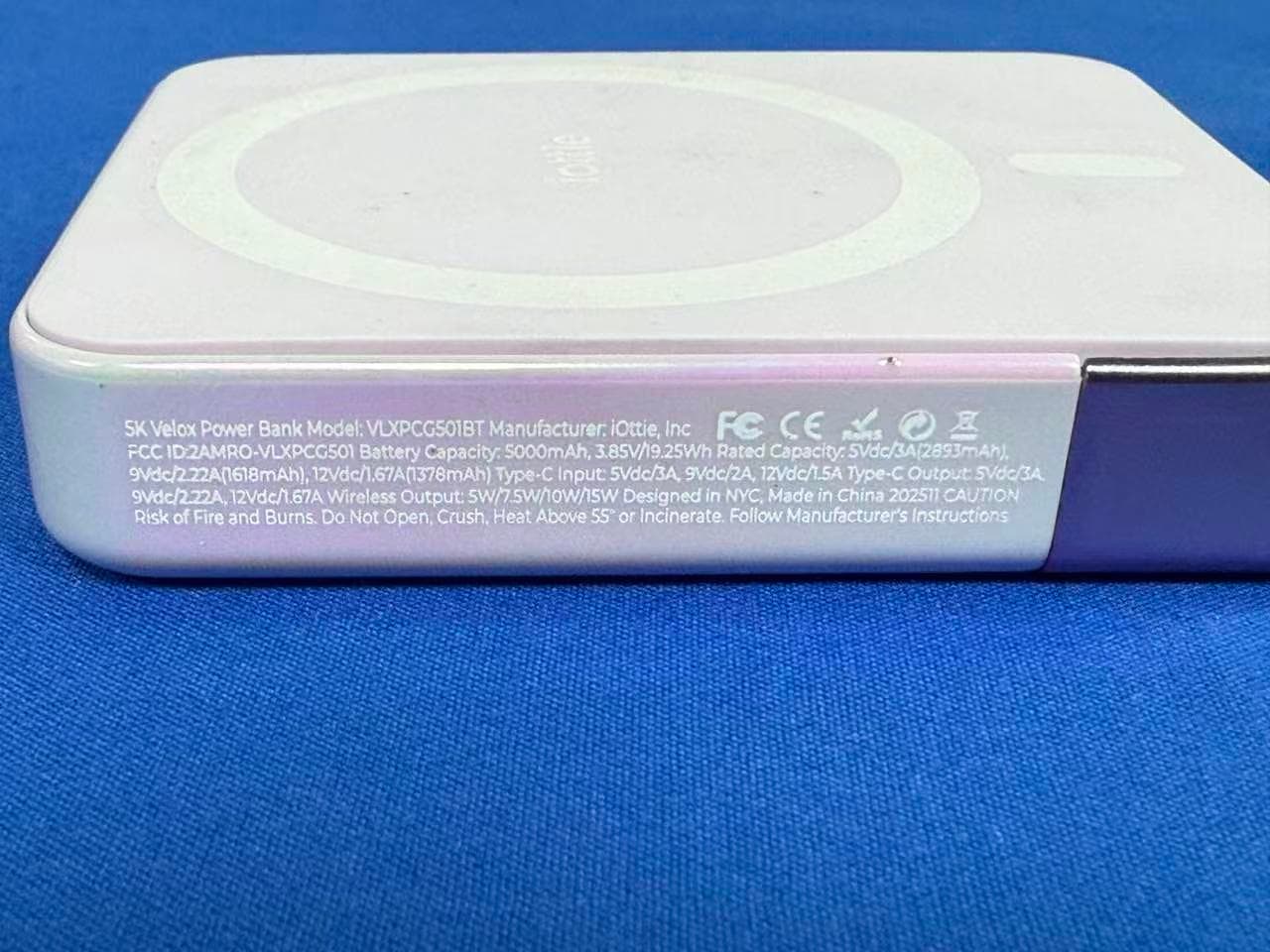
2AMRO-VLXPCG501
Dec 30, 2025Power Bank
Equipment Class
DCD - Part 15 Low Power Transmitter Below 1705 kHz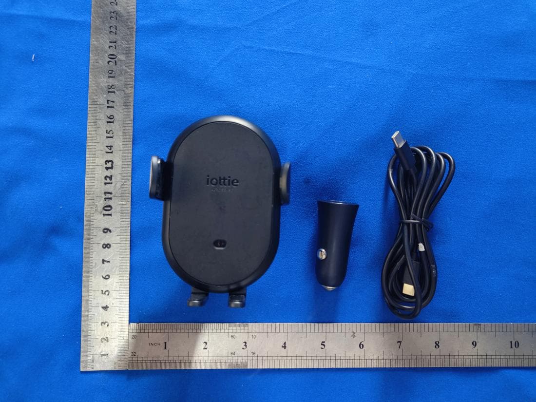
2AMRO-ATSWCG205
May 14, 2023iOttie Auto Sense 2 Dashboard & Air Vent Mount
Equipment Class
DCD - Part 15 Low Power Transmitter Below 1705 kHz
2AMRODCRMTE120
Aug 11, 2021Aivo View Dashcam Bluetooth Remote Button
Equipment Class
DTS - Digital Transmission System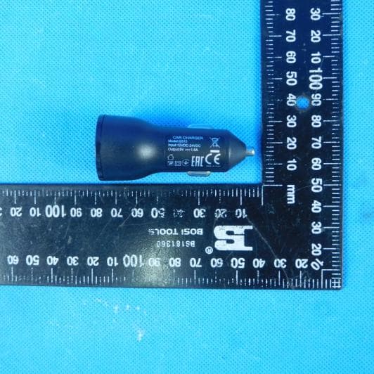
2AMRODCCRIO120
Jul 31, 2021Aivo View
Equipment Class
DTS - Digital Transmission System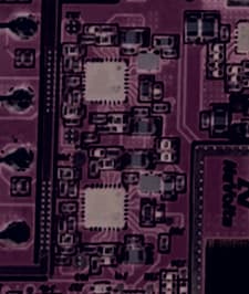
2AMRO-CHWRIO107GL
Sep 22, 2020iON wireless Duo
Equipment Class
8CC - Part 18 Consumer Device