2AN8FMSL-DZ001Auto Pair True Wireless Earbuds
Shenzhen Mossloo Industrial Co.,Ltd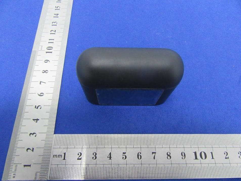
Click to zoom
Application Details
- Equipment Class
- DSS - Part 15 Spread Spectrum Transmitter
- Date of Grant
- Mar 16, 2021
- Application Purpose
- Original Equipment
- Date of Application
- Mar 16, 2021
- Equipment Note
- Auto Pair True Wireless Earbuds
- Frequency Range
- 2402.00000000 - 2480.00000000
- Country
- China
Documents & Files
Document Text
Text extracted from the exhibit documents filed with the FCC. Open a document above to read the original.
Users Manual
front side Looking Glass Auto Pair True Wireless Earbuds | 01 | 05 | 03 | 07 | 02 | 06 | 04 | 08 Instruction Manual 7197-46 Hello! This is your instruction manual, to help create the best possible experience with this cool product. Earbuds Power Case Type-C Charging Cable The battery isolators, on the bottom of the earbud stem, need to be removed in order to charge the earbuds. Place the earbuds securely into the power case. Earbuds will begin charging automatically. The charging case LED(4) will turn solid BLUE and earbud LED(2) will turn solid RED when charging. The LED on the earbuds and case will turn of f when the earbuds are fully charged. Use the provided USB to Type-C charging cable to connect to an adapter or computer to charge the power case. When charging the case the LED(4) will case is fully charged. It takes approximately 2.5hrs to charge the case from 0%-100%. When the case is fully charged it will charge the earbuds 4-5 times from 0%-100%. Remove both earbuds from the power case, you’ll hear a voice prompt on both earbuds saying “Power On” followed by the tone prompt indicating earbuds are paired. Once you hear both earbuds beep the earbuds are now synced to each other. If done successfully the main earbud LED will turn off and secondary earbud LED flash slowly. Go into your Bluetooth options and select the pairing name “Looking Glass TWS”. If done successfully you will hear the voice prompt “Connected”. You can now enjoy your favorite Audio. Previously connected earbuds will connect automatically after they’re powered ON. If you don’t connect to the earbuds within 3 minutes the earbuds will automatically power OFF. Remove your earbuds from the charging case or press and hold the multi-function sensor(1) for 3 seconds. You’ll hear the voice prompt “Power On”. holding the multi-function sensor on both earbuds until you hear the voice prompt “Power Off”. Right Earbud: - Double Press to play next song - Triple Press to increase volume Left Earbud: - Double press to play previous song. - Triple Press to decrease volume. If you’re having trouble pairing your earbuds forget the pairing name “Looking Glass TWS” from the list of connected devices. Now turn off your Bluetooth. Place both earbuds back into the charged power case. Now remove the earbuds and follow the instructions under “Pairing Both Earbuds”. Answering/End Call: Press the multifunction sensor once to answer an incoming call, and again to end the call. Reject a Call: Press and hold the multifunction sensor to reject an incoming call. To turn off your earbuds place them both back into the power case. You can also power off your earbuds by Multifunction Touch Sensor Microphone/ Earbud Charging LED Silicone Eartips Charging Case LED Type-C input port 1. 2. 3. 4. 5. ** • • • • • • • • • • • • • • • • • • • • • • • Safety Precautions: Included Contents: Functions: Charging: Pairing Both Earbuds: 1. Pairing: First time 2. Connecting to Bluetooth 3. Power ON 6. Playing Audio 5. Calling 4. Power OFF Resetting your earbuds: 1. Charging the earbuds 2. Charging the power case Please follow the rules described in this manual closely to ensure your safety. Before using the earbuds, we would strongly encourage you read this manual. Do not modify, repair or dismantle the earbuds or power bank. Do not use any liquids to clean the products. Do not use the earbuds near water or intense temperatures. 1. 2. 3. 4. 5. Press and hold the multifunction sensor on either earbud for 3 seconds, you will hear a beep prompt to indicate that your voice Assistand/Siri is “Activated” and waiting your commands. • 7. Activate Voice Assistant Extra Earbuds Tips: (Small & Large) back side | 09 | 13 | 1 1 | 15 | 10 | 14 | 12 | 16 Charging time Charging time Bluetooth Range Play time 1.5 hrs (from 0-100) 2.5 hrs (from 0-100) 10m 4 hrs at max volume WARNING–When using this product, basic precautions should always be followed, including the following: Fully read the instructions before using the product. The unit will only achieve full performance after 2 or 3 completed charge and discharge cycles. Do not overcharge your case. The unit may become hot under excessive use. Remove your case once it is fully charged. Never charge your case for more than 7 hours at a time. To reduce the risk of injury, close supervision is required when the product is used near children. Do not expose the device to moisture. Do not use the device in excess of its output rating. Overload outputs above the rating may explosion or risk of injury. Do not disassemble the device. Take the device required. Incorrect reassembly may result in a above 212ºF/100°C may cause explosion. person using only identical replacement parts. This will ensure that the safety of the product is maintained. approved by the party responsible for compliance could void the user’s authority to operate the equipment. This equipment has been tested and found to comply with the limits for a Class B digital device, pursuant to Part 15 of the FCC Rules.These limits are designed to provide reasonable protection against harmful interference in a residential installation. This equipment generates uses and can radiate radio frequency energy and, if not installed and used in accordance with the instructions, may cause harmful interference to radio communications. However, there is no guarantee that interference will not occur in a particular installation. If this equipment does cause harmful interference to radio or television reception, which can be determined by turning the equipment off and on, the user is encouraged to try to correct the interference by one or more of the following measures: Reorient or relocate the receiving antenna. Increase the separation between the equipment and receiver.Connect the equipment into an outlet on a circuit different from that to which the receiver is connected. Consult the dealer or an experienced radio/TV technician for help. This device complies with part 15 of the FCC rules.…
Text truncated - open the document above for the full version.
Cover Letter(s)
ShenZhen Mossloo Industrial Co.,Ltd 2021.03.10 Eurofins Electrical and Electronic Testing NA, Inc. 914 W. Patapsco Avenue Baltimore, MD 21230 USA RE: CONFIDENTIALITY REQUEST FOR EUT NAME: Auto Pair True Wireless Earbuds Trademark: N/A MODEL : MSL-DZ001, 7197-46 FCC ID: 2AN8FMSL-DZ001 To Whom It May Concern: This letter serves as an official request for confidentiality under sections 0.457 and 0.459 of CFR 47. We have requested that the - Block Diagram - Schematics - Operational Description required to be submitted with this application be permanently withheld from public review. The above materials contain trade secrets and proprietary information not customarily released to the public. The public disclosure of these materials may be harmful to the applicant and provide unjustified benefits to its competitors. Please contact me if there is any information you may need. Sincerely, Client’s signature: Client’s name / title : Orders Cheng /Manager Contact information / address: Road One No.4, Science Industrial Park, Shangxue Village, Bantian Street, Longgang District, Shenzhen, China
Cover Letter(s)
ShenZhen Mossloo Industrial Co.,Ltd 2021.03.10 Eurofins Electrical and Electronic Testing NA, Inc. 914 W. Patapsco Avenue Baltimore, MD 21230 USA RE: LETTER OF AGENT AUTHORIZATION To Whom It May Concern: We, the undersigned, hereby authorize Shenzhen BCTC Testing Co., Ltd to act on our behalf in all matters relating to application for equipment authorization, including the signing of all documents relating to these matters. We also hereby certify that no party to the application authorized hereunder is subject to the denial of benefits, including FCC benefits, pursuant to Section 5301 of the Anti-Drug Abuse Act of 1988, 21 U.S.C.853(a). This agreement expires one year from the current date. Sincerely, Client’s signature: Client’s name / title : Orders Cheng /Manager Contact information / address: Road One No.4, Science Industrial Park, Shangxue Village, Bantian Street, Longgang District, Shenzhen, China
Cover Letter(s)
Shenzhen Mossloo Industrial Co.,Ltd Model Difference 2021-03-10 EUT NAME: Auto Pair True Wireless Earbuds Trademark: N/A MODEL : MSL-DZ001, 7197-46 All the model are the same circuit and RF module, except model names. Regards Sincerely Client’s signature: Client’s name / title : Orders Cheng /Manager Contact information / address: Road One No.4, Science Industrial Park, Shangxue Village, Bantian Street, Longgang District, Shenzhen, China
External Photos
External Photos
ID Label/Location Info
Size:10*5mm FCC ID: 2AN8FMSL-DZ001 Label Location
Internal Photos
Internal Photos Antenna
RF Exposure Info
Shenzhen BCTC Testing Co., Ltd. FCC ID: 2AN8FMSL-DZ001 Portable device According to §15.247(e)(i) and §1.1307(b)(1), systems operating under the provisions of this section shall be operated in a manner that ensures that the public is not exposed to radio frequency energy level in excess of the Commission’s guidelines. According to KDB447498 D01 General RF Exposure Guidance V06 The 1-g SAR and 10-g SAR test exclusion thresholds for 100 MHz to 6 GHz at test separation distances ≤ 50 mm are determined by: [(max. power of channel, including tune-up tolerance, mW)/(min. test separation distance, mm)]·[√f(GHZ)] ≤ 3.0 for 1-g SAR and ≤ 7.5 for 10-g extremity SAR, where: • f(GHZ) is the RF channel transmit frequency in GHz • Power and distance are rounded to the nearest mW and mm before calculation • The result is rounded to one decimal place for comparison When the minimum test separation distance is < 5 mm, a distance of 5 mm is applied to determine SAR test exclusion. Modulation Channel Freq. (GHz) Conducte d power (dBm) Conducte d power (mW) Tune-up power (dBm) Max tune-up power (dBm) Max tune-up power (mW) Distance (mm) Result calculatio n SAR Exclusion threshold SAR test exclusion GFSK2.441-3.8930.41-3±1-2.000.63<50.197163.00YES Pi/4 DQPSK 2.441-3.0300.50-3±1-2.000.63<50.197163.00YES 8DPSK2.441-2.4150.57-2±1-1.000.79<50.248213.00YES Conclusion: For the max result : 0.24821<3.0, the SAR testing is not required.
Test Report
No.:BCTC/RF-EMC-005 Page: 1 of 71 Edition:A.3 TEST REPORT Shenzhen BCTC Testing Co., Ltd. Report No.: BCTC2102855277E Applicant: ShenZhen Mossloo Industrial Co.,Ltd Product Name: Auto Pair True Wireless Earbuds Model/Type Ref.: MSL-DZ001 Tested Date: 2021-02-23 to 2021-03-05 Issued Date: 2021-03-08 Report No.: BCTC2102855277E No.:BCTC/RF-EMC-005 Page: 2 of 71 Edition:A.3 FCC ID: 2AN8FMSL-DZ001 The test report is effective only with both signature and specialized stamp.This result(s) shown in this report refer only to the sample(s) tested. Without written approval of Shenzhen BCTC Testing Co., Ltd, this report can’t be reproduced except in full.The tested sample(s) and the sample information are provided by the client. Product Name: Auto Pair True Wireless Earbuds Trademark: N/A Model/Type Ref.: MSL-DZ001 7197-46 Prepared For: ShenZhen Mossloo Industrial Co.,Ltd Address: Road One No.4, Science Industrial Park, Shangxue Village, Bantian Street, Longgang District, Shenzhen, China Manufacturer: ShenZhen Mossloo Industrial Co.,Ltd Address: Road One No.4, Science Industrial Park, Shangxue Village, Bantian Street, Longgang District, Shenzhen, China Prepared By: Shenzhen BCTC Testing Co., Ltd. Address: 1-2/F., Building B, Pengzhou Industrial Park, No.158, Fuyuan 1st Road, Tangwei, Fuhai Subdistrict, Bao'an District, Shenzhen, Guangdong, China Sample Received Date: 2021-02-23 Sample tested Date: 2021-02-23 to 2021-03-05 Issue Date: 2021-03-08 Report No.: BCTC2102855277E Test Standards FCC Part15.247 ANSI C63.10-2013 Test Results PASS Remark: This is Bluetooth Classic radio test report. Tested by: Approved by: Eric Yang/Project Handler Zero Zhou/Reviewer Report No.: BCTC2102855277E No.:BCTC/RF-EMC-005 Page: 3 of 71 Edition:A.3 TABLE OF CONTENT Test Report Declaration Page 1. VERSION ............................................................ 5 2. TEST SUMMARY ..................................................... 6 3. MEASUREMENT UNCERTAINTY ....................................... 7 4. PRODUCT INFORMATION AND TEST SETUP............................ 8 4.1 Product Information ..................................................... 8 4.2 Test Setup Configuration ................................................ 8 4.3 Support Equipment ..................................................... 9 4.4 Channel List ........................................................... 9 4.5 Test Mode ............................................................ 10 5. TEST FACILITY AND TEST INSTRUMENT USED ........................ 11 5.1 Test Facility ........................................................... 11 5.2 Test Instrument Used .................................................. 11 6. CONDUCTED EMISSIONS ............................................ 13 6.1 Block Diagram Of Test Setup ............................................ 13 6.2 Limit ................................................................. 13 6.3 Test procedure ........................................................ 13 6.4 EUT operating Conditions ............................................... 14 6.5 Test Result ........................................................... 15 7. RADIATED EMISSIONS .............................................. 17 7.1 Block Diagram Of Test Setup ............................................ 17 7.2 Limit ................................................................. 18 7.3 Test procedure ........................................................ 19 7.4 EUT operating Conditions ............................................... 20 7.5 Test Result ........................................................... 21 8. RADIATED BAND EMISSION MEASUREMENT AND RESTRICTED BANDS OF OPERATION .................................................. 25 8.1 Block Diagram Of Test Setup ............................................ 25 8.2 Limit ................................................................. 25 8.3 Test procedure ........................................................ 26 8.4 EUT operating Conditions ............................................... 26 8.5 Test Result ........................................................... 27 9. CONDUCTED EMISSION ............................................. 28 9.1 Block Diagram Of Test Setup ............................................ 28 9.2 Limit ................................................................. 28 9.3 Test procedure ........................................................ 28 9.4 Test Result ........................................................... 29 10. 20 DB BANDWIDTH .................................................. 38 10.1 Block Diagram Of Test Setup .......................................... 38 10.2 Limit ................................................................ 38 Report No.: BCTC2102855277E No.:BCTC/RF-EMC-005 Page: 4 of 71 Edition:A.3 10.3 Test procedure ....................................................... 38 10.4 Test Result .......................................................... 39 11. MAXIMUM PEAK OUTPUT POWER .................................... 44 11.1 Block Diagram Of Test Setup .......................................... 44 11.2 Limit ................................................................ 44 11.3 Test procedure ....................................................... 44 11.4 Test Result .......................................................... 45 12. HOPPING CHANNEL SEPARATION ................................... 50 12.1 Block Diagram Of Test Setup .......................................... 50 12.2 Limit ................................................................ 50 12.3 Test procedure ....................................................... 50 12.4 Test Result .......................................................... 51 13. NUMBER OF HOPPING FREQUENCY .................................. 56 13.1 Block Diagram Of Test Setup .......................................... 56 13.2 Limit .......................................................…
Text truncated - open the document above for the full version.
Test Report
Report No.: BCTC2102855277E No.:BCTC/RF-EMC-005 Page: 47 of 71 Edition:A.3 Pi/4 DQPSK Low Channel Pi/4 DQPSK Middle Channel Report No.: BCTC2102855277E No.:BCTC/RF-EMC-005 Page: 48 of 71 Edition:A.3 Pi/4 DQPSK High Channel 8DPSK Low Channel Report No.: BCTC2102855277E No.:BCTC/RF-EMC-005 Page: 49 of 71 Edition:A.3 8DPSK Middle Channel 8DPSK High Channel Report No.: BCTC2102855277E No.:BCTC/RF-EMC-005 Page: 50 of 71 Edition:A.3 12. HOPPING CHANNEL SEPARATION 12.1 Block Diagram Of Test Setup 12.2 Limit Frequency hopping systems shall have hopping channel carrier frequencies separated by a minimum of 25 kHz or the 20 dB bandwidth of the hopping channel, whichever is greater. Alternatively, frequency hopping systems operating in the 2400-2483.5 MHz band may have hopping channel carrier frequencies that are separated by 25 kHz or two-thirds of the 20 dB bandwidth of the hopping channel, whichever is greater, provided the systems operate with an output power no greater than 0.125W. 12.3 Test procedure 1. Remove the antenna from the EUT and then connect a low RF cable from the antenna port to the spectrum. 2. Set the spectrum analyzer: RBW = 30kHz. VBW = 100kHz , Span = 2.0MHz. Sweep = auto; Detector Function = Peak. Trace = Max hold. 3. Allow the trace to stabilize. Use the marker-delta function to determine the separation between the peaks of the adjacent channels. The limit is specified in one of the subparagraphs of this Section Submit this plot. Report No.: BCTC2102855277E No.:BCTC/RF-EMC-005 Page: 51 of 71 Edition:A.3 12.4 Test Result Modulation Test Channel Separation (MHz) Limit(MHz) Result GFSK Low 1.000 0.587 PASS GFSK Middle 0.998 0.586 PASS GFSK High 1.002 0.585 PASS Pi/4 DQPSK Low 0.998 0.840 PASS Pi/4 DQPSK Middle 1.000 0.841 PASS Pi/4 DQPSK High 0.998 0.839 PASS 8DPSK Low 1.000 0.833 PASS 8DPSK Middle 1.002 0.815 PASS 8DPSK High 1.002 0.831 PASS Test plots GFSK Low Channel Report No.: BCTC2102855277E No.:BCTC/RF-EMC-005 Page: 52 of 71 Edition:A.3 GFSK Middle Channel GFSK High Channel Report No.: BCTC2102855277E No.:BCTC/RF-EMC-005 Page: 53 of 71 Edition:A.3 Pi/4 DQPSK Low Channel Pi/4 DQPSK Middle Channel Report No.: BCTC2102855277E No.:BCTC/RF-EMC-005 Page: 54 of 71 Edition:A.3 Pi/4 DQPSK High Channel 8DPSK Low Channel Report No.: BCTC2102855277E No.:BCTC/RF-EMC-005 Page: 55 of 71 Edition:A.3 8DPSK Middle Channel 8DPSK High Channel Report No.: BCTC2102855277E No.:BCTC/RF-EMC-005 Page: 56 of 71 Edition:A.3 13. NUMBER OF HOPPING FREQUENCY 13.1 Block Diagram Of Test Setup 13.2 Limit Frequency hopping systems in the 2400-2483.5 MHz band shall use at least 15 channels. 13.3 Test procedure 1. Remove the antenna from the EUT and then connect a low RF cable from the antenna port to the spectrum. 2. Set the spectrum analyzer: RBW = 100kHz. VBW = 300kHz. Sweep = auto; Detector Function = Peak. Trace = Max hold. 3. Allow the trace to stabilize. It may prove necessary to break the span up to sections. in order to clearly show all of the hopping frequencies. The limit is specified in one of the subparagraphs of this Section. 4. Set the spectrum analyzer: Start Frequency = 2.4GHz, Stop Frequency = 2.4835GHz. Sweep=auto; Report No.: BCTC2102855277E No.:BCTC/RF-EMC-005 Page: 57 of 71 Edition:A.3 13.4 Test Result Test Plots: 79 Channels in total GFSK Pi/4 DQPSK Report No.: BCTC2102855277E No.:BCTC/RF-EMC-005 Page: 58 of 71 Edition:A.3 8DPSK Report No.: BCTC2102855277E No.:BCTC/RF-EMC-005 Page: 59 of 71 Edition:A.3 14. DWELL TIME 14.1 Block Diagram Of Test Setup 14.2 Limit Frequency hopping systems in the 2400-2483.5 MHz band shall use at least 15 channels. The average time of occupancy on any channel shall not be greater than 0.4 seconds within a period of 0.4 seconds multiplied by the number of hopping channels employed. Frequency hopping systems may avoid or suppress transmissions on a particular hopping frequency provided that a minimum of 15 channels are used. 14.3 Test procedure 1. Remove the antenna from the EUT and then connect a low RF cable from the antenna port to the spectrum. 2. Set spectrum analyzer span = 0. Centred on a hopping channel; 3. Set RBW = 1MHz and VBW = 3MHz.Sweep = as necessary to capture the entire dwell time per hopping channel. Set the EUT for DH5, DH3 and DH1 packet transmitting. 4. Use the marker-delta function to determine the dwell time. If this value varies with different modes of operation (e.g.. data rate. modulation format. etc.). repeat this test for each variation. The limit is specified in one of the subparagraphs of this Section. Submit this plot(s). Report No.: BCTC2102855277E No.:BCTC/RF-EMC-005 Page: 60 of 71 Edition:A.3 14.4 Test Result DH5 Packet permit maximum 1600 / 79 / 6 hops per second in each channel (5 time slots RX, 1 time slot TX). DH3 Packet permit maximum 1600 / 79 / 4 hops per second in each channel (3 time slots RX, 1 time slot TX). DH1 Packet permit maximum 1600 / 79 /2 hops per second in each channel (1 time slot RX, 1 time slot TX). So, the Dwell Time can be calculated as follows: DH5:1600/79/6*0.4*79*(MkrDelta)/1000 DH3:1600/79/4*0.4*79*(MkrDelta)/1000 DH1:1600/79/2*0.4*79*(MkrDelta)/1000 Remark: Mkr Delta is once pulse time. Modulation Channel Data Packet pulse time(ms) Dwell Time(s) Limits(s) GFSK Middle DH1 0.388 0.124 0.4 DH3 1.656 0.265 0.4 DH5 2.910 0.310 0.4 Pi/4DQPSK Middle 2DH1 0.400 0.128 0.4 2DH3 1.662 0.266 0.4 2DH5 2.920 0.311 0.4 8DPSK Middle 3DH1 0.402 0.129 0.4 3DH3 1.662 0.266 0.4 3DH5 2.920 0.311 0.4 Test Plots GFSK DH1 Middle Channel Report No.: BCTC2102855277E No.:BCTC/RF-EMC-005 Page: 61 of 71 Edition:A.3 GFSK DH3 Middle Channel GFSK DH5 High Middle Channel Report No.: BCTC2102855277E No.:BCTC/RF-EMC-005 Page: 62 of 71 Edition:A.3 Pi/4DQPSK DH1 Middle Channel Pi/4DQPSK DH3 Middle Channel Report No.: BCTC2102855277E No.:BCTC/RF-EMC-005 Page: 63 of 71 Edition:A.3 Pi/4DQPSK DH5 Middle Channel 8DPSK DH1 Middle Channel Report No.: BCTC2102855277E No.:BCTC/RF-EMC-005 Page: 64 of 71 Edition:A.3 8DPSK DH3 Middle Channel…
Text truncated - open the document above for the full version.
Test Setup Photos
Conducted emissions Radiated Measurement Photos
Contact Information
Applicant
Orders Cheng
Technical Contact
Shenzhen BCTC Testing Co., Ltd.Alan Mei
[email protected]86-755-36882589
1-2/F., Building B, Pengzhou Industrial Park, · Baoan District, Shenzhen, Guangdong · China
Test Firm
Shenzhen BCTC Testing Co., Ltd.Sally He
[email protected]15999690624
Technical Specifications
| # | Rule Parts | Frequency Range | Power Output |
|---|---|---|---|
| 1 | 15C | 2.40 GHz - 2.48 GHz | 500.00 µW |
Other Applications from Shenzhen Mossloo Industrial Co.,Ltd
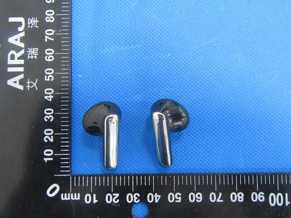
2AN8F573-M3012
Sep 26, 2022TWS Earbuds
Equipment Class
DSS - Part 15 Spread Spectrum Transmitter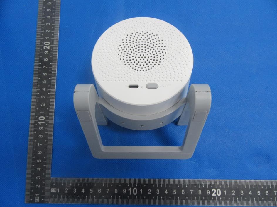
2AN8F966-M6064Q
Jul 13, 2022Wireless charging Bluetooth speaker with RGB
Equipment Class
DSS - Part 15 Spread Spectrum Transmitter
2AN8FMSL-M9012
Jun 19, 2022Bluetooth speaker with RGB
Equipment Class
DSS - Part 15 Spread Spectrum Transmitter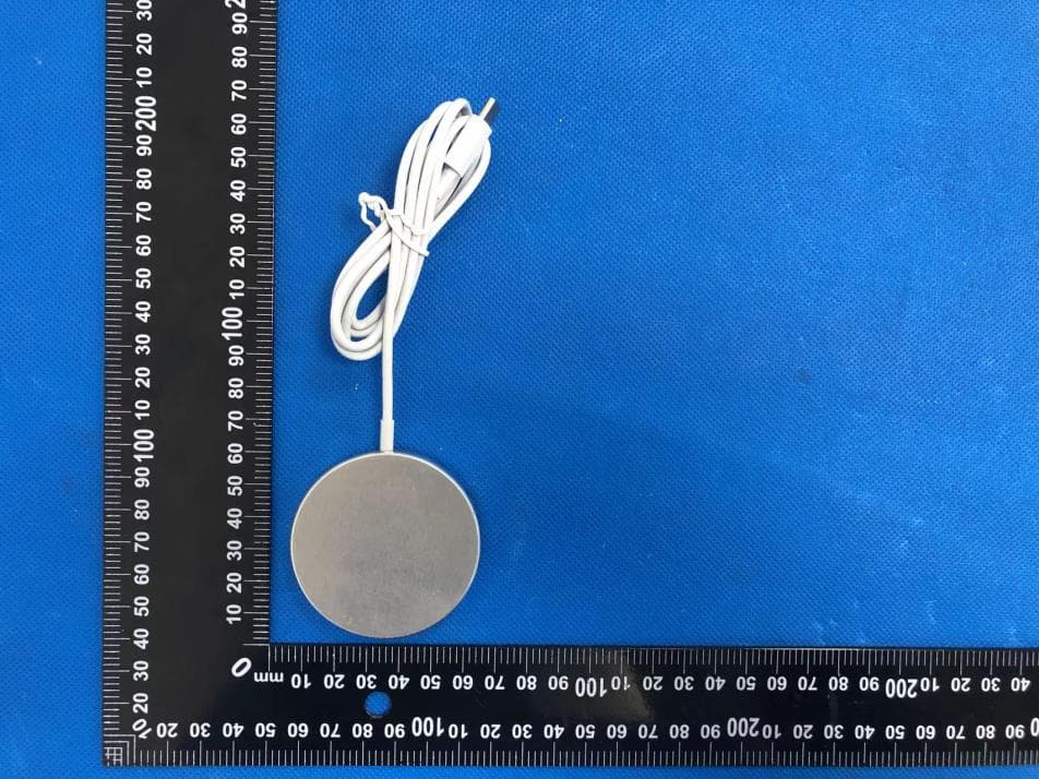
2AN8FM1029-A
Apr 13, 2022Fast Wireless Charger
Equipment Class
DCD - Part 15 Low Power Transmitter Below 1705 kHz
2AN8F-M1025Q
Apr 13, 2022Fast Wireless Charger
Equipment Class
DCD - Part 15 Low Power Transmitter Below 1705 kHz