2AN8FMSL-M6023QUVC Sterilizer w/ Wireless Power Bank
Shenzhen Mossloo Industrial Co.,Ltd
Click to zoom
Application Details
- Equipment Class
- DCD - Part 15 Low Power Transmitter Below 1705 kHz
- Date of Grant
- Aug 20, 2020
- Application Purpose
- Original Equipment
- Date of Application
- Aug 20, 2020
- Equipment Note
- UVC Sterilizer w/ Wireless Power Bank
- Frequency Range
- 0.11200000 - 0.22000000
- Country
- China
Documents & Files
Document Text
Text extracted from the exhibit documents filed with the FCC. Open a document above to read the original.
Users Manual
UVC Sterilizer w/ Wireless Power Bank Instruction Manual MSL-M6023Q 1 x UV Sanitizer w/ Wireless Power Bank 1 x USB-A to Type-C Cable 1 x Instruction Manual Capacity: 10000mAh/3.7V/37Wh Type-C Input: DC 5V/2A USB Output: DC 5V/2A Wireless Output: 5W a wireless charging device or there is an object between the device and charging surface interfering with the charging process. Using the UV Sanitizing Function: Press the UV-C Lights Button(4) to turn on the BLUE when UV Sterilizing has started. The UV lights will turn off itself after 5mins, or press button(4) to turn off UV lights. (There will be a tick sound and the LED will turn off once sterilizing is done.) DO NOT LIFT UP THE COVER(7) ONCE THE SANITIZING PROCESS HAS STARTED: The UV LED will automatically shut off when you open the lid during sanitizing process. explosion or risk of injury. Do not disassemble the device. For professional. incorrect reassembly may or temperatures above 104°F may cause explosion. use only identical replacement parts to ensure product safety. Attachments on the back of your phone can impede the effectiveness of the wireless charger, and lead to overheating. Please remove any attachments from the phone before charging on this device. Charging the Powerbank: Be sure to charge the powerbank fully before usage. Connect the provided charging cable to a power source and to the Type-C port on the powerbank(6). Once connected the LED Indicator will Charging Mobile Phones and other Electronic Devices: Connect the charging cable to your mobile phone/device using the appropriate connector. Connect the USB part of the cable to the USB-A Output(5) of the powerbank. The LED will glow WHITE when charging. Remove the USB cable from your mobile device when it is fully charged. Wireless Charging Mobile phones and other electronic devices: Press the Powerbank ON/OFF button(3) to turn on the wireless charging function. The 2nd LED Indicator will glow GREEN once the power bank is in wireless charging standby mode. Place wireless charging supported mobile device on the charging surface(8), the 2nd LED will glow RED when device is charging. Note: When wireless charging, if 2nd LED 1. • • • 2. • • • 3. • • ** 1. 2. 3. 4. 5. 6. 7. 8. • • • • 4. • • ** 9. 10. 11. 12. 13. UV-C Lights LED Indicators ON/OFF Button UV-C lights ON/OFF Button USB-A Output Port Type-C Input Port Cover Wireless Charging Surface/ Sanitizing Compartment General Lights What’s included: Functions: Instructions: This device complies with Part 15 of the FCC Rules. Operation is subject to the following two conditions: This device may not cause harmful interference, and This device must accept any interference received, including interference that may cause undesired operation. Warning: approved by the party responsible for compliance could void the user’s authority to operate the equipment. (1) (2) * FCC Statement: MADE IN CHINA WARNING-When using this product, basic precautions should always be followed: Read all the instructions before use. Never store or use this product in temperatures below 32°F(0°C) or above 115°F(45°C). Do not overcharge your phone. The unit may become hot under excessive use. Remove your phone once it is fully charged. Never charge your phone for more than 7 hours at a time. The unit will only achieve full performance after 2 or 3 completed charge and discharge cycles. To reduce the risk of injury, close supervision is required when the product is used near children. Do not expose the device to moisture. Do not use the device in excess of its output rating. Overload outputs above the Do not use the device if damaged or • 1. 2. 3. 4. 5. 6. 7. 8. SAFETY PRECAUTIONS: ON/OFF Button(3): Press once to view the remaining power capacity. • LED Indicators: 9. 9 EPA Est. NO.: FCC Caution: This device complies with part 15 of the FCC Rules. Operation is subject to the following two conditions: (1) This device may not cause harmful interference, and (2) this device must accept any interference received, including interference that may cause undesired operation. Any Changes or modifications not expressly approved by the party responsible for compliance could void the user's authority to operate the equipment. Note: This equipment has been tested and found to comply with the limits for a Class B digital device, pursuant to part 15 of the FCC Rules. These limits are designed to provide reasonable protection against harmful interference in a residential installation. This equipment generates uses and can radiate radio frequency energy and, if not installed and used in accordance with the instructions, may cause harmful interference to radio communications. However, there is no guarantee that interference will not occur in a particular installation. If this equipment does cause harmful interference to radio or television reception, which can be determined by turning the equipment off and on, the user is encouraged to try to correct the interference by one or more of the following measures: -Reorient or relocate the receiving antenna. -Increase the separation between the equipment and receiver. -Connect the equipment into an outlet on a circuit different from that to which the receiver is connected. -Consult the dealer or an experienced radio/TV technician for help. The device has been evaluated to meet general RF exposure requirement. The device can be used in portable exposure condition without restriction.
Cover Letter(s)
Shenzhen Mossloo Industrial Co.,Ltd Agent Authorization Company: Shenzhen Mossloo Industrial Co.,Ltd Address: Road One No.4, Science Industrial Park, Shangxue Village, Bantian Street, Longgang District, Shenzhen, China Product Name: UVC Sterilizer w/ Wireless Power Bank Trademark: N/A Model Number(s): MSL-M6023Q, 7121-78 FCC ID: 2AN8FMSL-M6023Q We authorize MiCOM Labs Inc., 575 Boulder Court, Pleasanton, California 94566, USA, to act on our behalf on all matters concerning the certification of above named equipment. We declare that MiCOM Labs Inc. is allowed to forward all information related to the approval and certification of equipment to the regulatory agencies as required and to discuss any issues concerning the approval application. Any and all acts carried out by MiCOM Labs on our behalf shall have the same effect as acts of our own. Signature: Date: 2020/08/12 Name: Orders Cheng Title: Manager Company: Shenzhen Mossloo Industrial Co.,Ltd
Cover Letter(s)
Shenzhen Mossloo Industrial Co.,Ltd Office of Engineering Technology Federal Communications Commission 7435 Oakland Mills Road Columbia, MD 21046 USA Date: 2020/08/12 Subject; Request for Confidentiality FCC ID: 2AN8FMSL-M6023Q To Whom It May Concern, Pursuant to the provisions of the Commission’s rules Title 47 Sections §0.457 and §0.459, we are requesting the Commission to withhold the following attachment(s) as confidential documents from public disclosure indefinitely. These documents contain detailed system and equipment descriptions and are considered as proprietary information in operation of the equipment. The public disclosure of these documents might be harmful to our company and would give competitors an unfair advantage in the market. Schematic Diagram Block Diagram Operational Description In additional to above mentioned documents, in order to comply with the marketing regulations in Title 47 CFR §2.803 and the importation rules in Title 47 CFR §2.1204, while ensuring that business sensitive information remains confidential until the actual marketing of newly authorized devices, we request Short Term Confidentiality of the following attachment(s); User Manual For 45 days, pursuant to Public Notice DA 04-1705. OR For 180 days pursuantto KDB 726920 D01. It is our understanding that all measurement test reports, FCC ID label format and correspondence during the certification review process cannot be granted as confidential documents and this information will be available for public review once the grant of equipment authorization is issued. Sincerely, Signature: Name: Orders Cheng Title: Manager
Cover Letter(s)
Shenzhen Mossloo Industrial Co.,Ltd Model Difference 2020/08/12 Product Name: UVC Sterilizer w/ Wireless Power Bank Trademark: N/A Model Number(s): MSL-M6023Q, 7121-78 FCC ID: 2AN8FMSL-M6023Q All the model are the same circuit and RF module, except model names. Regards Sincerely Client’s signature: Client’s name / title : Orders Cheng /Manager Contact information / address: Road One No.4, Science Industrial Park, Shangxue Village, Bantian Street, Longgang District, Shenzhen, China
External Photos
External Photos
ID Label/Location Info
Size:20*10mm FCC ID: 2AN8FMSL-M6023Q This device complies with Part 15 of the FCC Rules. Operation is subject to the following two conditions:(1)This device may not cause harmful interfer ence, and (2) this device must accept any interference received, including interference that may cause undesired operation. Label Location
Internal Photos
Internal Photos Antenna
RF Exposure Info
Shenzhen BCTC Testing Co., Ltd. Report No.: BCTC2007002342-1E Test Report Tel: 400-788-9558 Web: https://www.bctc-lab.com BCTC/RF-EMC-009 Ver.:A.0 Page 1 of 14 RF EXPOSURE REPORT For FCC ID: 2AN8FMSL-M6023Q Product Name: UVC Sterilizer w/ Wireless Power Bank Trademark: N/A Model Number: MSL-M6023Q 7121-78 Prepared For : ShenZhen Mossloo Industrial CO., Ltd. Address : Road One No.4, Science Industrial Park, Shangxue Village, Bantian Street, Longgang District, Shenzhen, China Prepared By : Shenzhen BCTC Testing Co., Ltd. Address : BCTC Building & 1-2F, East of B Building, Pengzhou Industrial, Fuyuan 1st Road, Qiaotou Community, Fuyong Street, Bao’an District, Shenzhen, China Test Date: Jul. 29, 2020 to Aug. 4, 2020 Date of Report : Aug. 5, 2020 Report No.: BCTC2007002342-1E Shenzhen BCTC Testing Co., Ltd. Report No.: BCTC2007002342-1E Test Report Tel: 400-788-9558 Web: https://www.bctc-lab.com BCTC/RF-EMC-009 Ver.:A.0 Page 2 of 14 TEST RESULT CERTIFICATION Applicant’s name ................. : ShenZhen Mossloo Industrial CO., Ltd. Address ................................. : Road One No.4, Science Industrial Park, Shangxue Village, Bantian Street, Longgang District, Shenzhen, China Manufacture's Name ............ : ShenZhen Mossloo Industrial CO., Ltd. Address ................................. : Road One No.4, Science Industrial Park, Shangxue Village, Bantian Street, Longgang District, Shenzhen, China Product description Product name ........................... : UVC Sterilizer w/ Wireless Power Bank Trademark ............................ : N/A Model and/or type reference : MSL-M6023Q 7121-78 Serial Model : N/A Power Supply : Battery: DC 3.7V Input:DC5V/2A USB Output: DC5V/2A Wireless Output: 5W Standards ............................. : FCC CFR 47 part1, 1.1307(b), 1.1310 This device described above has been tested by BCTC, and the test results show that the equipment under And it is applicable only to the tested sample identified in the report. This report shall not be reproduced except in full, without the written approval of BCTC, this document may be altered or revised by BCTC, personal only, and shall be noted in the revision of the document. Prepared by(Engineer): Willem Wang Reviewer(Supervisor): Eric Yang Approved(Manager): Zero Zhou Shenzhen BCTC Testing Co., Ltd. Report No.: BCTC2007002342-1E Test Report Tel: 400-788-9558 Web: https://www.bctc-lab.com BCTC/RF-EMC-009 Ver.:A.0 Page 3 of 14 Table of Contents Page 1 . GENERAL INFORMATION 4 1.1 . Independent Operation Mode 4 1.2 . Test Supporting System 4 2 .LIST OF TEST AND MEASUREMENT INSTRUMENTS 5 2.1 . For conducted emission at the mains terminals test 5 3. METHOD OF MEASUREMENT 6 3. 1.Applicable Standard 6 3. 2. Test Modes 6 3. 3. MAXIMUM PERMISSIBLE EXPOSURE 6 4. TEST RESULT 7 4.1. Conducted Emission at the Mains Terminals Test 7 4.2. Equipment Approval Considerations: 8 4.3. E and H field Strength 9 5. Photographs of test set-up 10 Shenzhen BCTC Testing Co., Ltd. Report No.: BCTC2007002342-1E Test Report Tel: 400-788-9558 Web: https://www.bctc-lab.com BCTC/RF-EMC-009 Ver.:A.0 Page 4 of 14 1. GENERAL INFORMATION 1.1. Independent Operation Mode The basic operation mode is: 1.1.1. Charging 1.2. Test Supporting System Mobile phone Model No. : iphone8P Shenzhen BCTC Testing Co., Ltd. Report No.: BCTC2007002342-1E Test Report Tel: 400-788-9558 Web: https://www.bctc-lab.com BCTC/RF-EMC-009 Ver.:A.0 Page 5 of 14 2.LIST OF TEST AND MEASUREMENT INSTRUMENTS 2.1. For conducted emission at the mains terminals test Equipment Manufacturer Model No. Serial No. Last Cal. Next Cal. Exposure Level Tester Narda ELT-400 N-0231 Jul. 07, 2020 Jul. 06, 2021 Magnetic field probe 100cm2 Narda B-Field Probe 100cm2 M0675 Jul. 07, 2020 Jul. 06, 2021 843 Chamber ETS 843 84301 Aug. 27, 2020 Aug. 26, 2023 Shenzhen BCTC Testing Co., Ltd. Report No.: BCTC2007002342-1E Test Report Tel: 400-788-9558 Web: https://www.bctc-lab.com BCTC/RF-EMC-009 Ver.:A.0 Page 6 of 14 3. METHOD OF MEASUREMENT 3. 1.Applicable Standard According to §1.1307(b)(1), systems operating under the provisions of this section shall be operated in a manner that ensures that the public is not exposed to radio frequency energy level in excess of the Commission’s guidelines. According to §1.1310 and §2.1093 RF exposure is calculated. According KDB680106 D01v03: RF Exposure Wireless Charging Apps v02. 3. 2. Test Modes Test Modes keeping TX+Charging mode 3. 3. MAXIMUM PERMISSIBLE EXPOSURE Shenzhen BCTC Testing Co., Ltd. Report No.: BCTC2007002342-1E Test Report Tel: 400-788-9558 Web: https://www.bctc-lab.com BCTC/RF-EMC-009 Ver.:A.0 Page 7 of 14 4. TEST RESULT 4.1. Conducted Emission at the Mains Terminals Test Note: Measurements should be made from all sides and the top of the primary/client pair, with the 15 cm measured from the center of the probe(s) to the edge of the device Test Procedure: a) The RF exposure test was performed on 360 degree turn table in anechoic chamber. b) The measurement probe was placed at test distance (15cm) which is between the edge of the charger and the geometric centre of probe. c) The turn table was rotated 360d degree to search of highest strength. d) The highest emission level was recorded and compared with limit as soon as measurement of each points (A, B, C, D, E) were completed. e) The EUT were measured according to the dictates of KDB 680106D01v03. Shenzhen BCTC Testing Co., Ltd. Report No.: BCTC2007002342-1E Test Report Tel: 400-788-9558 Web: https://www.bctc-lab.com BCTC/RF-EMC-009 Ver.:A.0 Page 8 of 14 4.2. Equipment Approval Considerations: The EUT does comply with item 5(b) of KDB 680106 D01v03 1) Power transfer frequency is less than 1MHz Yes, the device operate in the frequency range from 112-220KHz 2) Output power from each primary coil is less than or equal to 15 watts. Yes, the maximum output power of the primary coil is 5W. 3) The transfer system includes only single primary and secondary coils. This includes charging systems that may have multiple …
Text truncated - open the document above for the full version.
Test Report
Shenzhen BCTC Testing Co., Ltd. Report No.: BCTC2007002342-2E Test Report Tel: 400-788-9558 Web: https://www.bctc-lab.com BCTC/RF-EMC-013 Ver.:A.0 Page 1 of 21 FCC TEST REPORT FCC ID: 2AN8FMSL-M6023Q Product Name: UVC Sterilizer w/ Wireless Power Bank Trademark: N/A Model Number: MSL-M6023Q 7121-78 Prepared For : ShenZhen Mossloo Industrial CO., Ltd. Address : Road One No.4, Science Industrial Park, Shangxue Village, Bantian Street, Longgang District, Shenzhen, China Prepared By : Shenzhen BCTC Testing Co., Ltd. Address : BCTC Building & 1-2F, East of B Building, Pengzhou Industrial, Fuyuan 1st Road, Qiaotou Community, Fuyong Street, Bao’an District, Shenzhen, China Test Date: Jul. 29, 2020 to Aug. 4, 2020 Date of Report : Aug. 5, 2020 Report No.: BCTC2007002342-2E Shenzhen BCTC Testing Co., Ltd. Report No.: BCTC2007002342-2E Test Report Tel: 400-788-9558 Web: https://www.bctc-lab.com BCTC/RF-EMC-013 Ver.:A.0 Page 2 of 21 TABLE OF CONTENTS TEST REPORT DECLARATION .................................................................................................. 3 1. GENERAL INFORMATION ........................................................................................................ 4 1.1. Report information .......................................................................................................................... 4 1.2. Measurement Uncertainty .............................................................................................................. 4 1.3. Test Facility ...................................................................................................................................... 4 1.4. Test Uncertainty .............................................................................................................................. 4 2. PRODUCT DESCRIPTION ......................................................................................................... 5 2.1. EUT Description .............................................................................................................................. 5 2.2. Test mode ........................................................................................................................................ 5 2.3. Block Diagram of EUT Configuration ........................................................................................... 5 2.4. Test Conditions ................................................................................................................................ 5 2.5. Description Of Support Units (Conducted Mode) ....................................................................... 6 3. TEST RESULTS SUMMARY ..................................................................................................... 6 4. TEST EQUIPMENT USED .......................................................................................................... 7 4.1. For Conducted Emission Test ....................................................................................................... 7 4.2. For Radiated Emission Measurement ......................................................................................... 7 5. CONDUCTED EMISSION TEST ................................................................................................ 8 5.1. Block Diagram of Test Setup......................................................................................................... 8 5.2. Test Standard .................................................................................................................................. 8 5.3. Conducted Emission Limit ............................................................................................................. 8 5.4. EUT Configuration on Test ............................................................................................................ 8 5.5. Operating Condition of EUT .......................................................................................................... 9 5.6. Test Procedure ................................................................................................................................ 9 5.7. Test Result ....................................................................................................................................... 9 6. RADIATED EMISSION MEASUREMENT ............................................................................. 12 6.1. Block Diagram of Test Setup....................................................................................................... 12 6.2. Test Standard and Limit ............................................................................................................... 13 6.3. EMI Test Receiver Setup ............................................................................................................. 14 6.4. Test Procedure .............................................................................................................................. 14 6.5. Test Result ..................................................................................................................................... 14 7. EUT TEST PHOTOS .................................................................................................................. 18 8. EUT PHOTOS ............................................................................................................................. 20 Shenzhen BCTC Testing Co., Ltd. Report No.: BCTC2007002342-2E Test Report Tel: 400-788-9558 Web: https://www.bctc-lab.com BCTC/RF-EMC-013 Ver.:A.0 Page 3 of 21 TEST REPORT DECLARATION Applicant : ShenZhen Mossloo Industrial CO., Ltd. Address : Road One No.4, Science Industrial Park, Shangxue Village, Bantian Street, Longgang District, Shenzhen, China EUT Description : UVC Sterilizer w/ Wireless Power Bank Model Number : MSL-M6023Q Test Standards: FCC Part 15 C This device described above has been tested by BCTC, and the test results show t…
Text truncated - open the document above for the full version.
Test Setup Photos
Shenzhen BCTC Testing Co., Ltd. Conducted Measurement Photos Shenzhen BCTC Testing Co., Ltd. Radiated Measurement Photos 9KHz-30MHz 30MHz-1GHz
Contact Information
Applicant
Orders Cheng
Technical Contact
Test Firm
Shenzhen BCTC Testing Co., Ltd.Sally He
[email protected]15999690624
Technical Specifications
| # | Rule Parts | Frequency Range | Power Output |
|---|---|---|---|
| 1 | 15C | 0.112 MHz - 0.22 MHz | - |
Other Applications from Shenzhen Mossloo Industrial Co.,Ltd
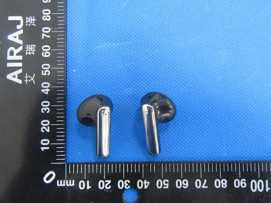
2AN8F573-M3012
Sep 26, 2022TWS Earbuds
Equipment Class
DSS - Part 15 Spread Spectrum Transmitter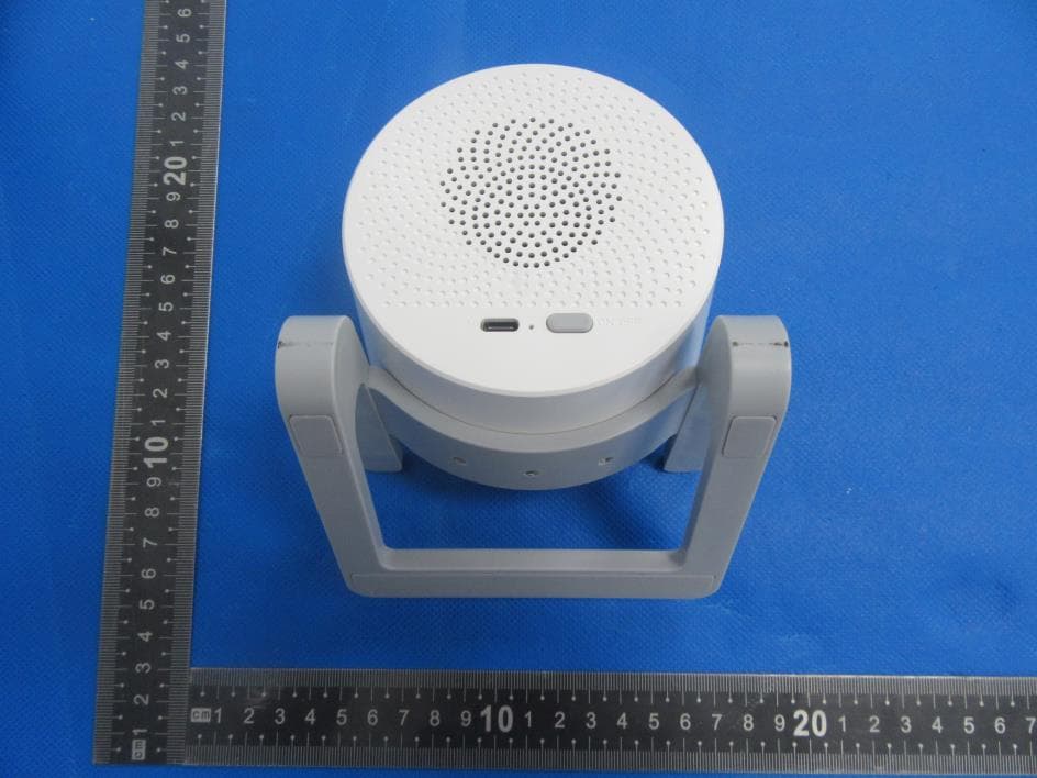
2AN8F966-M6064Q
Jul 13, 2022Wireless charging Bluetooth speaker with RGB
Equipment Class
DSS - Part 15 Spread Spectrum Transmitter
2AN8FMSL-M9012
Jun 19, 2022Bluetooth speaker with RGB
Equipment Class
DSS - Part 15 Spread Spectrum Transmitter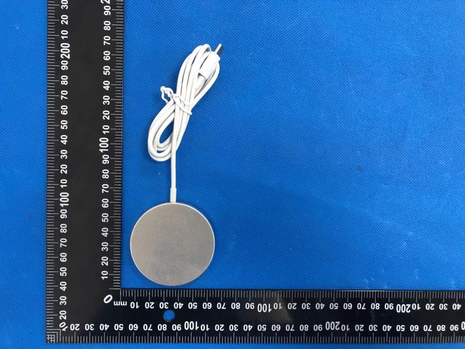
2AN8FM1029-A
Apr 13, 2022Fast Wireless Charger
Equipment Class
DCD - Part 15 Low Power Transmitter Below 1705 kHz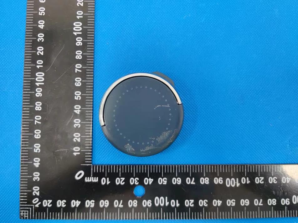
2AN8F-M1025Q
Apr 13, 2022Fast Wireless Charger
Equipment Class
DCD - Part 15 Low Power Transmitter Below 1705 kHz