2AN9X-RSS2300WLNon-Contact Flow Meter
Geolux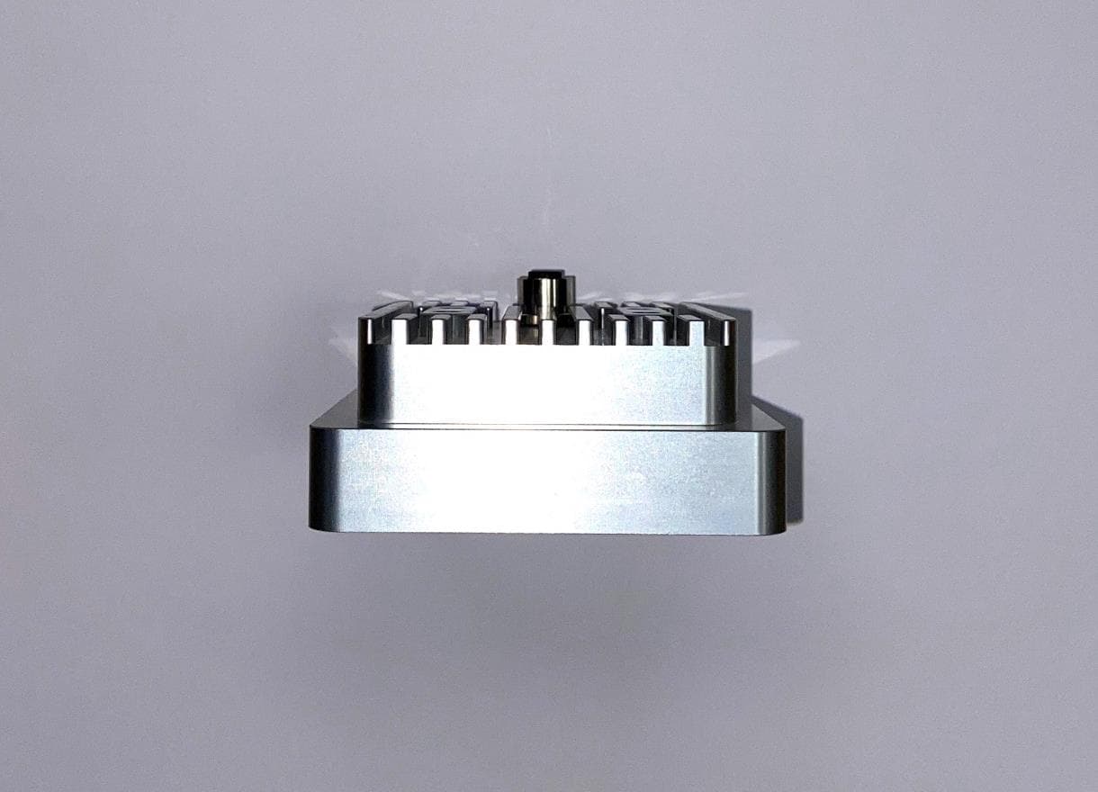
Click to zoom
Application Details
- Equipment Class
- FDS - Part 15 Field Disturbance Sensor
- Date of Grant
- Sep 04, 2024
- Application Purpose
- Original Equipment
- Date of Application
- Sep 04, 2024
- Equipment Note
- Non-Contact Flow Meter
- Frequency Range
- 24158.30000000 - 24158.30000000
- Company
- Geolux
- Country
- Croatia
Documents & Files
Document Text
Text extracted from the exhibit documents filed with the FCC. Open a document above to read the original.
Users Manual
Copyright ©2023 Geolux d.o.o. All rights reserved. RSS-2-300WL Non-Contact Flow Meter User Manual v6.7.9 Starting Point Thank you for purchasing Geolux RSS-2-300WL non-contact open channel flow meter! We have put together the experience of our engineers, the domain knowledge of our customers, the enthusiasm of our team, and the manufacturing excellence to deliver this product to you. You may freely rely on our field-proven radar technology. The use of top-quality components and advanced signal processing algorithms ensures that Geolux level meter can be used in various applications and environments. We have created this User Manual to assist you in setting up and using the Geolux instrument. Should there be any questions left unanswered, please feel free to contact us directly: Geolux d.o.o. Ljudevita Gaja 62 10430 Samobor Croatia E-mail: [email protected] Web: www.geolux.hr Contents 1. Introduction 1 2. Electrical Characteristics 2 3. C able Pin-Out 4 3.1. Serial R S-232 Interface 5 3.2. Serial RS-485 Interface 5 3.3. CAN Communication Interface (Optional) 6 3.4. Analog 4 – 20 mA Output 6 3.4.1. C onnection to Schneider TM3AM6 analog input module 7 3.5. SDI-12 Inter face 8 4. Ins talling the Flow Meter 9 4.1. Ins trument Mounting and Location Selection 9 4.2. Measur ement Quality Indicator 11 4.3. Rain and Wind 12 4.4. Inter ference and Multiple Radars 12 4.5. F ogging and Evaporation 1 3 4.6. Re flections 13 5. Flo w Meter Settings 15 6. Data Interface 27 6.1. Serial R S-232 Interface 27 6.2. Serial R S-485 Interface 27 7. Data Protocols 28 7.1. NME A Protocol (RS-232) 28 7.2. Ser vicing Protocol (RS-232) 32 7.3. HS P rotocol 45 7.4. Modbus P rotocol (RS-485) 46 7.4.1. Modbus Input Regis ters 56 7.5. SDI-12 Protocol 5 7 8. Dynamic Flow Profiler 61 9. Radar C onfigurator Utility 62 9.1. Configuring the Unit for Discharge Calculation 66 9.1.1. De fining the Channel Profile Geometry Manually 67 9.1.2. Selec ting a Predefined Channel Profile Shape 70 9.1.3. Discharge Parameters Estimation 74 9.2. Dynamic Flow Profiler 75 9.2.1. Getting the DFP Measurements Status 75 9.2.2. Displaying the Saved DFP Measurements 76 9.2.3. Importing/Exporting Measurements for a Specific Level 77 9.2.4. Importing/Exporting Measurements for All Defined Levels 78 10. Calculating Discharge from Surface Velocity and Liquid Level 80 11. T roubleshooting 82 12. Appendix A – Mechanical Assembly 88 RSS-2-300WL User Manual 1RSS-2-300WL Non-Contact Flow Meter 1 Introduction Geolux RSS-2-300WL flow meter uses radar technology to provide precise contactless measurement of surface flow velocity and precise distance (level) measurement from the sensor to the water surface. Fully contactless radar technology enables quick and simple sensor installation above the water surface and requires minimum maintenance. Surface velocity measurement functionality is achieved by transmitting an electromagnetic wave in 24 GHz frequency range (K-band) and measuring the frequency shift of the electromagnetic wave reflected from the flowing water surface. The frequency shift is caused by the Doppler effect of the moving surface on the electromagnetic wave. As the relative speed between the radar sensor and the water surface increases, the detected frequency shift also increases, thus enabling the flow meter to precisely determine the surface velocity. Water level is measured by measuring the distance from the sensor to the water surface, which is proportional to the frequency difference between the transmitted and the received signal. The radar periodically transmits a linear chirp ranging in frequency from 77 GHz to 81 GHz. As the distance between the radar and the water surface increases, so does the difference between the transmitted and received frequency, enabling the level meter to precisely determine the distance between the sensor and the water surface. The radio signal modulation and detection algorithms used in the sensor allow very precise measurements that are not dependent on air temperature, humidity, or other parameters of the environment. The flow meter is able to detect water surface velocity ranging from 0.02 m/s to 15.0 m/s with precision of 0.001 m/s while the distance can be measured in range from 0.2 m to 15 m or 30 m with resolution of 0.5 mm and accuracy of ±2 mm. An integrated tilt sensor measures the inclination angle of the sensors and the surface velocity measurement is automatically cosine- corrected according to the measured mounting tilt angle. The flow meter is able to measure water flow at distances ranging from 0.2 m up to either 15 m or 30 m, depending on the device version: WL-15-1 is the 15 m version of the device, and WL-30-1 is the 30 m version. Calculation of the flow (discharge) is done internally in the sensor combining surface velocity measurement and level measurement with configured cross section of the river or channel. Configuration of the measurement parameters like channel profile cross section, material of the edges and the location of the sensor above the water can be easily set using Geolux PC configuration application - Geolux Instrument Configurator. When parameters are set properly, the sensor will calculate flow with an accuracy of approximately ±1% compared to ADCP measurement for the same location. Measurements of the surface velocity and water level will also be available in parallel to the flow readings on the sensor digital communication interfaces. RSS-2-300WL User Manual 2RSS-2-300WL Non-Contact Flow Meter 2 Electrical Characteristics The electrical characteristics of the Geolux RSS-2-300WL flow meter are given in Table 1. Table 1. Electrical Characteristics ParameterMINTYPMAXUnit Communication interface: RS-232 interface speed RS-485 interface speed 1200 1200 115200 115200 bps bps Radar Velocity Sensor Frequency Radiated power (EIRP) Sensitivity Beam-width (3dB) – Azimuth Beam-width (3dB) – Elevation Measurement range Resolution Accuracy Installation height above the water 24.075…
Text truncated - open the document above for the full version.
Attestation Statements
Page 1/1 Geolux d.o.o. Ljudevita Gaja 62 HR-10430 Samobor, Croatia EU VAT ID: HR52616021041 TO: American Certification Body, Inc. 313 Park Avenue Suite 300 Falls Church, VA 22046 ATTENTION: FCC Certification – Section 2.911(d)(7) Information Designated U.S. Agent Company Name: Contact Name: Street Address: City/Province/Zip: Telephone No: Email: Advanced Environnement Monitoring Intermediate, Inc. Ryan Guerrero 12410 Milestone Center Drive Germantown, MD 20876 301-250-4000 [email protected] N/A FRN # if one exists: This letter is to confirm that we (“the Designated U.S. Agent) have accepted the responsibility to act as the Designated U.S. Agent for Service of Process as required by section 47 CFR 2.911(d)(7) on behalf of the Applicant noted below. U.S. Agent Signature: Da te: Th e Applicant acknowledges that they must maintain an agent for no less than one year after terminating all marketing and importation OR the conclusion of any Commission-related proceeding involving the equipment. The applicant further acknowledges their responsibility to inform the FCC whenever the Designated U.S. Agent information above changes. Applicant Company name: Geolux Grantee Code: 2AN9X Contact Name: Tomislav Grubesa, Director Street Address: Ljudevita Gaja 62 City/Province/Zip: Samobor, 10430 Croatia Telephone No: +385 1 6701 241 Email: [email protected] Applicant Signature: Date: 25 th June 2024 Signed by (Printed Name/Title): Tomislav Grubesa, director 07/01/24 Signed by (Printed Name/Title):
Attestation Statements
Page 1/1 Geolux d.o.o. Ljudevita Gaja 62 HR-10430 Samobor, Croatia EU VAT ID: HR52616021041 Date: 4 th July 2024 American Certification Body, Inc. 313 Park Avenue Suite 300 Falls Church, VA 22046 To Whom It May Concern: Statement for 47 CFR section 2.911(d)(5)(i) Geolux certifies that as of the date of the application the equipment for which authorization is sought is not “covered” equipment prohibited from receiving an equipment authorization pursuant to section 2.903 of the FCC rules. If the equipment for which the applicant seeks authorization is produced by any of the entities identified on the current Covered List, including affiliates or subsidiaries of the named companies, the applicant must include an explanation on why the equipment is not “covered” equipment. Additional Explanation: <N/A> Statement for 47 CFR section 2.911(d)(5)(ii) Geolux (“the applicant”) certifies that, as of the date of the filing of this application, the applicant is not identified on the Covered List as an entity producing “covered” equipment. Thank you, By: Tomislav Grubeša _ (Signature) (Print name) Title: CTO Company: Geolux d.o.o. Telephone: +385917244004
Cover Letter(s)
Page 1/1 Geolux d.o.o. Ljudevita Gaja 62 HR-10430 Samobor, Croatia EU VAT No.: HR52616021041 Request for Confidentiality Date: 16.07.2024. Subject: Confidentiality Request for: FCC ID: 2AN9X-RSS2300WL / IC: 26475-RSS2300WL Pursuant to FCC 47 CFR 0.457(d) and 0.459 and IC RSP-100, Section 9.4, the applicant requests that a part of the subject FCC application be held confidential. Type of Confidentiality Requested Exhibit ☐Short Term☒PermanentBlock Diagrams ☐Short TermExternal Photos ☒Short Term☐Permanent *1Internal Photos ☐Short TermOperation Description/Theory of Operation ☐Short Term ☒Permanent Parts List & Placement/BOM ☐Short Term☐PermanentTune-Up Procedure ☐Short Term☒PermanentSchematics ☐Short TermTest Setup Photos ☐Short Term☐Permanent *3User’s Manual Geolux d.o.o. has spent substantial effort in developing this product and it is one of the first of its kind in industry. Having the subject information easily available to "competition" would negate the advantage they have achieved by developing this product. Not protecting the details of the design will result in financial hardship. Permanent Confidentiality: The applicant requests the exhibits listed above as permanently confidential be permanently withheld from public review due to materials that contain trade secrets and proprietary information not customarily released to the public. Short-Term Confidentiality: The applicant requests the exhibits selected above as short term confidential be withheld from public view for a period of 180 days from the date of the Grant of Equipment Authorization and prior to marketing. This is to avoid premature release of sensitive information prior to marketing or release of the product to the public. Applicant is also aware that they are responsible to notify ACB in the event information re- garding the product or the product is made available to the public before the requested period has ex- pired. ACB will then release the documents listed above for public disclosure pursuant to FCC Public Notice DA 04-1705. NOTE for Industry Canada Applications: Starting May 2022, ISED will recognize short term confidentiality on certain exhibits until the intended date of marketing. The applicant requests the exhibits selected above as short term confidential be with- held from public view until: 01 st Feb 2025. Sincerely, By: Tomislav Grubesa, M.Sc., CTO (Signature/Title2) (Print name) ☐Permanent
Cover Letter(s)
Page 1/1 Geolux d.o.o. Ljudevita Gaja 62 HR-10430 Samobor, Croatia EU VAT ID: HR52616021041 Authority to Act as Agent Date: 4th July 2024 American Certification Body, Inc. 313 Park Avenue Suite 300 Falls Church, VA 22046 To Whom It May Concern: Rhein Tech Laboratories, Inc./Kathy Grzovic is authorized to act on our behalf, until otherwise notified, for applications to American Certification Body, Inc . (ACB). We certify that we are not subject to denial of federal benefits, that includes FCC benefits, pursuant to Section 5301 of the Anti-Drug Abuse Act of 1988, 21 U.S.C. 862. Further, no party, as defined in 47 CFR 1.2002 (b), to the application is subject to denial of federal benefits, that includes FCC benefits. We also declare that the information provided to the FCC is true and correct to the best of our knowledge (47 CFR 2.911(d)) and we have been informed of the grantee responsibilities (47 CFR 2.909) with regard to certified equipment. Thank you, Agency Agreement Expiration Date: 31 st July 2025 By: Tomislav Grubeša _ (Signature) (Print name) Title: CTO On behalf of: Geolux d.o.o. (Company Name) Telephone: +385917244004
External Photos
Page 1/3 Geolux d.o.o. Ljudevita Gaja 62 HR-10430 Samobor, Croatia EU VAT ID: HR52616021041 1.1 EUT Front View 1.2 EUT Back View Page 2/3 1.3 EUT Left View 1.4 EUT Right View Page 3/3 1.5 EUT Top View 1.6 EUT Bottom View FCC ID: 2AN9XLX801; IC: 26475-LX801
ID Label/Location Info
Page 1/2 Geolux d.o.o. Ljudevita Gaja 62 HR-10430 Samobor, Croatia EU VAT No.: HR52616021041 Label Location and Photos Date: 07.08.2024. Subject: 2AN9X-RSS2300WL / 26475-RSS2300WL Label is located on the back side of the product between mounting brackets. The label is made from polyester with silver color and filmic coating. The label is printed by special laser printer, and it is attached to the enclosure by permanent adhesive. Label is designed by manufacturer for permanent marking of products being used indoors and outdoors with special resistance to water, oil, dirt, UV rays and extreme temperatures (-40°C to + 150°C). Ideal for applying to metal, plastic, painted surface, fabric, polycarbonate and glass, both indoors and outside. Label design: Label location: Page 2/2 Label photo:
RF Exposure Info
Rhein Tech Laboratories, Inc. Client: Geolux d.o.o. 360 Herndon Parkway Model/HVIN: RSS-2-300WL Suite. 1400 IDs: 2AN9X-RSS2300WL/26475-RSS2300WL Herndon, VA 20170 Standards: Part 15.256/RSS-211 http://www.rheintech.com Project #: 2023076DXX 27 of 34 Appendix A: RF Exposure Compliance FCC Rules and Regulations Part 1.1307, 1.1310, 2.1091, 2.1093; ISED RSS-102 Radio Frequency (RF) Exposure Compliance of Radiocommunication Apparatus (All Frequency Bands) General Information Environment: General Population/Uncontrolled Exposure Device category: Level Probing Radar Modulation Type/Mode: Pulsed Radar List of Antennas, Operating Configurations and Test Conditions FCC 15.256 Antennas Antenna Gain (dBi) Dielectric Lens Patch Array 27.0 Patch Array 19.0 The maximum permissible RF exposure for a controlled environment is specified in FCC 1.1310 Table 1A. From OET 65, S = EIRP / 4πR 2 where: S = Power density (mw/cm 2 ) EIRP = Equivalent Isotropic Radiated Power R = 20 cm separation distance For the above device operating at 77-81 GHz or 24.125 GHz, the MPE limit for a controlled environment is 5 mW/cm 2 and the MPE limit for an uncontrolled environment is 1 mW/cm 2 . ISED RSS-102 §5.3.2 From Table 7: 15000-150000 MHz; Uncontrolled environment 10 W/m 2 or 1 mW/cm 2 . From Table 8: 15000-150000 MHz; Controlled environment 50 W/m 2 or 5 mW/cm 2 . Power Density for Surface Velocity Sensor (24.125 GHz) 1. The Surface Velocity Sensor (SVS) fundamental field strength = 115.4 dBuV/m at 3 meters = 20.2 dBm. 2. The maximum antenna gain for this frequency range of operation is 19 dBi / 79.4 numeric. 3. The EIRP + 1 dB tune-up tolerance = 21.2 dBm = 131.8 mW. 4. S = 0.03 mW/cm 2 = at 20 cm separation. Rhein Tech Laboratories, Inc. Client: Geolux d.o.o. 360 Herndon Parkway Model/HVIN: RSS-2-300WL Suite. 1400 IDs: 2AN9X-RSS2300WL/26475-RSS2300WL Herndon, VA 20170 Standards: Part 15.256/RSS-211 http://www.rheintech.com Project #: 2023076DXX 28 of 34 Power Density for Radar Level Sensor ( 77-81 GHz) 1. The Level Sensor (LS) operational description power level = 15.8 dBm. 2. The maximum antenna gain for this frequency range of operation is 27 dBi / 501.2 numeric. 3. The EIRP + 1 dB tune-up tolerance = 16.8 dBm = 47.9 mW. 4. S = 0.0095 mW/cm 2 = at 20 cm separation. Calculation of Co-Location MPE per Section 7.2 of KDB 447498 D01 General RF Exposure Guidance v06. Co-location - Summary of MPE: Surface Velocity Sensor and Level Sensor Transmitter Frequency (GHz) MPE Result (mW/cm 2 ) Limit (mW/cm 2 ) Ratio Surface Velocity Sensor 24.125 0.03 1.0 0.03 Level Sensor 77-81 0.0095 1.0 0.0095 Sum of Ratios 0.0395 Rounding up the sum of the ratios per FCC KDB policy, the sum of the ratios must be <1. The sum of ratios = 0.04 <1 Thus, the EUT meets the uncontrolled exposure limit at 20 cm when all transmitters transmit simultaneously and does NOT require MPE measurement.
Test Report
Engineering Solutions & Electromagnetic Compatibility Services 360 Herndon Pkwy | Suite 1400 | Herndon | Virginia 20170 Phone: 703.689.0368 | Fax: 703.689.2056 | www.rheintech.com FCC & ISED Canada Certification Application Report Test Lab: Rhein Tech Laboratories, Inc. Tel: 703-689-0368 360 Herndon Parkway www.rheintech.com Suite 1400 Herndon, VA 20170 Applicant: Geolux d.o.o. Tel: +385 1 6701 241 Ljudevita Gaja 62 Samobor, 10430 Croatia FCC ID IC 2AN9X-RSS2300WL 26475-RSS2300WL Test Report Date August 12, 2024 Platform N/A RTL Work Order # 2023076FDS Model / HVIN RSS-2-300WL RTL Quote # QRTL23-0 76B American National Standard Institute ANSI C63.10-2020: American National Standard of Procedures for Compliance Testing of Unlicensed Wireless Devices FCC Classification FDS - Field Disturbance Sensor FCC Rule Part(s)/ Guidance FCC Rules Part 15.245: Operation within the bands 902–928 MHz, 2435– 2465 MHz, 5785–5815 MHz, 10500–10550 MHz, and 24075–24175 MHz (10-01-21) ISED Canada RSS-Gen Issue 5: General Requirements for Compliance of Radio Apparatus RSS-210 Issue 10 – Low Power Licence-Exempt Radiocommunication Devices (All Frequency Bands) Category I Equipment Digital Interface Information Digital Interface was found to be compliant Frequency Range (MHz) Output Power* (W) Frequency Tolerance Emission Designator 24125 N/A N/A N/A I, the undersigned, hereby declare that the equipment tested and referenced in this report conforms to the identified standard(s) as described in this test report. No modifications were made to the equipment during testing in order to achieve compliance with these standards. Furthermore, there was no deviation from, additions to, or exclusions from, the applicable parts of FCC Part 2, FCC Part 15, ISED RSS-Gen and ANSI C63.10. Signature: Date: August 12, 2024 Typed/Printed Name: Desmond A. Fraser Position: President This report may not be reproduced, except in full, without the written approval of Rhein Tech Laboratories, Inc. and Geolux d.o.o. The test results relate only to the item(s) tested. Replaces Report R1.1. These tests are accredited and meet the requirements of ISO/IEC 17025 as verified by ANAB. Refer to certificate and scope of accreditation AT-1445 Rhein Tech Laboratories, Inc. Client: Geolux d.o.o. 360 Herndon Parkway Model/HVIN: RSS-2-300WL Suite 1400 Standards: FCC 15.245/RSS-210 Herndon, VA 20170 IDs: 2AN9X-RSS2300WL/26475-RSS2300WL http://www.rheintech.com Report #: 2023076FDS Page 2 of 23 Table of Contents 1 General Information ............................................................................................................................... 4 1.1 Scope ............................................................................................................................................... 4 1.2 Description of EUT ........................................................................................................................... 4 1.3 Test Facility ...................................................................................................................................... 4 1.4 Measurement Uncertainty ................................................................................................................ 4 1.5 Related Submittal(s)/Grant(s) .......................................................................................................... 4 1.6 Modifications .................................................................................................................................... 4 2 Test Information ..................................................................................................................................... 5 2.1 Description of Test Modes ............................................................................................................... 5 2.2 Exercising the EUT .......................................................................................................................... 5 2.3 Test Result Summary ....................................................................................................................... 5 2.4 Test System Details ......................................................................................................................... 5 3 Radiated Emissions – FCC 15.209, 15.245(b); RSS-Gen, RSS-210 .................................................... 7 3.1 Limits of Radiated Emissions Measurement .................................................................................... 7 3.2 Radiated Emissions Measurement Test Procedure ........................................................................ 7 3.3 Radiated Emissions Test Results .................................................................................................... 9 3.4 Radiated Emissions Harmonics/Spurious Test Data ..................................................................... 10 3.5 Radiated Emissions Digital Test Data ............................................................................................ 11 4 AC Conducted Emissions - FCC 15.207; RSS-Gen ............................................................................ 13 4.1 Test Methodology for Conducted Line Emissions Measurements ................................................ 13 4.2 Conducted Line Emission Test Procedure ..................................................................................... 13 5 20 dB Bandwidth – FCC 15.215(c); RSS-Gen .................................................................................... 16 5.1 20 dB Bandwidth Test Procedure .................................................................................................. 16 5.2 Bandwidth Test Data ...................................................................................................................... 16 5.3 20 dB Bandwidth Plot ..................................................................................................................... 17 6 Concl…
Text truncated - open the document above for the full version.
Test Setup Photos
Rhein Tech Laboratories, Inc. Client: Geolux d.o.o. 360 Herndon Parkway Model/HVIN: RSS-2-300WL Suite 1400 Standards: FCC 15.245/RSS-210 Herndon, VA 20170 IDs: 2AN9X-RSS2300WL/26475-RSS2300WL http://www.rheintech.com Report #: 2023076FDS Page 18 of 23 Appendix A: Test Configuration Photographs Photograph 1: Radiated Emissions – Front View Above 1 GHz Rhein Tech Laboratories, Inc. Client: Geolux d.o.o. 360 Herndon Parkway Model/HVIN: RSS-2-300WL Suite 1400 Standards: FCC 15.245/RSS-210 Herndon, VA 20170 IDs: 2AN9X-RSS2300WL/26475-RSS2300WL http://www.rheintech.com Report #: 2023076FDS Page 19 of 23 Photograph 2: Radiated Emissions – Rear View Above 1 GHz Rhein Tech Laboratories, Inc. Client: Geolux d.o.o. 360 Herndon Parkway Model/HVIN: RSS-2-300WL Suite 1400 Standards: FCC 15.245/RSS-210 Herndon, VA 20170 IDs: 2AN9X-RSS2300WL/26475-RSS2300WL http://www.rheintech.com Report #: 2023076FDS Page 20 of 23 Photograph 3: Radiated Emissions – Front View Below 1 GHz Rhein Tech Laboratories, Inc. Client: Geolux d.o.o. 360 Herndon Parkway Model/HVIN: RSS-2-300WL Suite 1400 Standards: FCC 15.245/RSS-210 Herndon, VA 20170 IDs: 2AN9X-RSS2300WL/26475-RSS2300WL http://www.rheintech.com Report #: 2023076FDS Page 21 of 23 Photograph 4: Radiated Emissions – Rear View Below 1 GHz Rhein Tech Laboratories, Inc. Client: Geolux d.o.o. 360 Herndon Parkway Model/HVIN: RSS-2-300WL Suite 1400 Standards: FCC 15.245/RSS-210 Herndon, VA 20170 IDs: 2AN9X-RSS2300WL/26475-RSS2300WL http://www.rheintech.com Report #: 2023076FDS Page 22 of 23 Photograph 5: AC Conducted Emissions – Front View Rhein Tech Laboratories, Inc. Client: Geolux d.o.o. 360 Herndon Parkway Model/HVIN: RSS-2-300WL Suite 1400 Standards: FCC 15.245/RSS-210 Herndon, VA 20170 IDs: 2AN9X-RSS2300WL/26475-RSS2300WL http://www.rheintech.com Report #: 2023076FDS Page 23 of 23 Photograph 6: AC Conducted Emissions - Rear View
Contact Information
Applicant
Tomislav Grubesa(Director)
Technical Contact
Rhein Tech Laboratories, Inc.Desmond Fraser
[email protected]5208346834
360 Herndon Parkway · Herndon · United States
Test Firm
Rhein Tech Laboratories, Inc.Richard McMurray
Technical Specifications
| # | Rule Parts | Frequency Range | Power Output |
|---|---|---|---|
| 1 | 15.245 | 24.16 GHz - 24.16 GHz | - |
Other Applications from Geolux
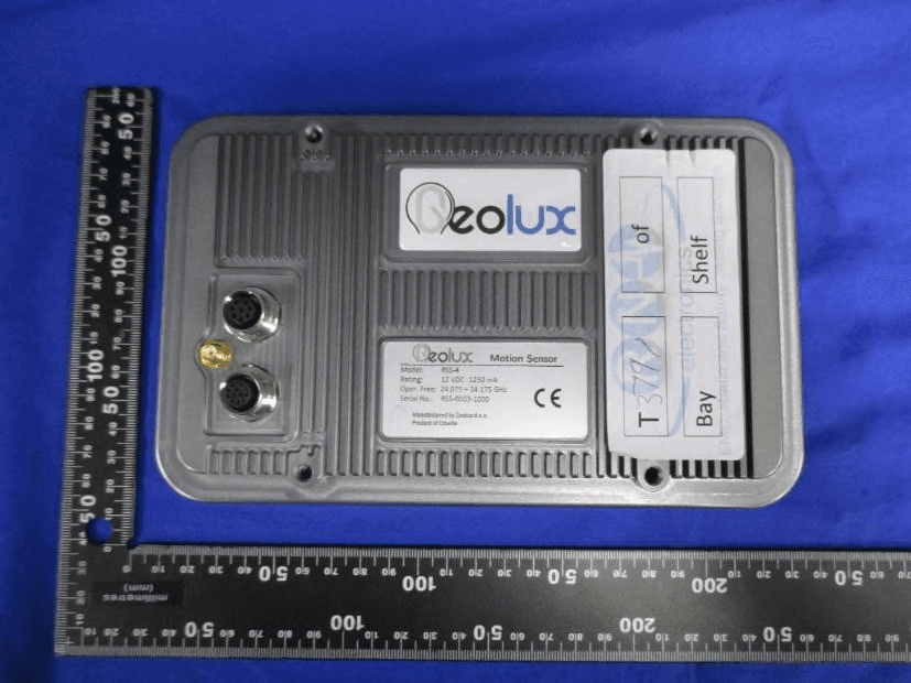
2AN9XRSS4001
Feb 01, 2021Geolux RSS-4 Ground Surveillance Radar
Equipment Class
DXX - Part 15 Low Power Communication Device Transmitter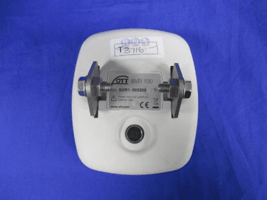
2AN9XRSS2301W
Apr 29, 2020OTT SVR 100 Surface Velocity Radar
Equipment Class
FDS - Part 15 Field Disturbance Sensor