2AN9XRSS2301WOTT SVR 100 Surface Velocity Radar
Geolux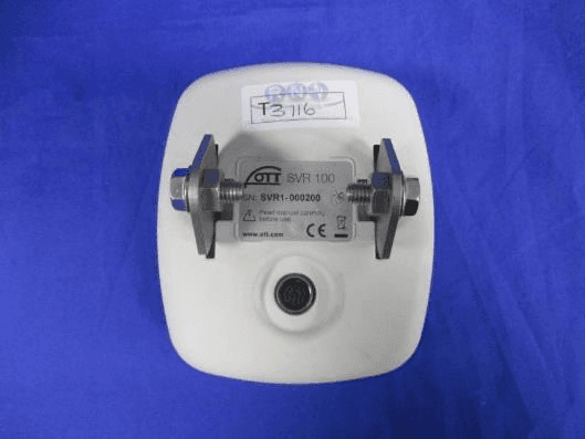
Click to zoom
Application Details
- Equipment Class
- FDS - Part 15 Field Disturbance Sensor
- Date of Grant
- Apr 29, 2020
- Application Purpose
- Original Equipment
- Date of Application
- Apr 29, 2020
- Equipment Note
- OTT SVR 100 Surface Velocity Radar
- Frequency Range
- 24125.00000000 - 24125.00000000
- Company
- Geolux
- Country
- Croatia
Documents & Files
Document Text
Text extracted from the exhibit documents filed with the FCC. Open a document above to read the original.
Users Manual
E n g l i s h Operating Instructions Surface Velocity Radar OTT SVR 100 We reserve the right to make technical improvements! 3 Table of contents 1 Scope of supply 4 2 Order numbers 4 3 Basic safety instructions 5 4 Introduction 6 5 Installing the OTT SVR 100 9 5.1 Criteria for selecting a suitable installation location 9 5.2 Information on supply voltage 11 5.3 Compatible cable types 11 5.4 Installing the OTT SVR 100 12 5.5 Connecting the OTT SVR 100 to the data logger 16 5.6 Information on using the RS-485 interface 16 6 SDI-12-commands and responses 17 6.1 Overview of standard SDI-12 commands 17 6.2 Standard commands 18 6.2 Advanced SDI-12 commands 20 7 Performing maintenance work 22 8 Repairs 22 9 Information on disposal of old devices 23 10 Troubleshooting 24 11 Technical Data 25 Appendix A – Connecting the OTT SVR 100 to OTT netDL via the RS-485 interface 26 Appendix B – Wall bracket dimensions/mounting hole positions 28 Appendix C – Note on the declaration of conformity 29 Appendix D – RS-485 interface with Modbus protocol (RTU) 30 Appendix E – OTT SVR 100 Operating Program 32 1 Scope of supply ! OTT SVR100 – Radar sensor for contactless measurement of the surface velocity of a flowing waterway; with RS-232- and RS-485-interface (SDI-12- or Modbus protocol) – Installation accessory kit (two-piece swivel mount, consisting of device and wall brackets, and four M8 hexagon bolts) – Connecting cable, 10 m; with 12-pin angled connector – Quick guide – Acceptance test certificate (FAT) 2 Order numbers ! OTT SVR100 OTT SVR 100 radar sensor – RS-485 interface with SDI-12 protocol (preset) 63.151.001.9.0 – RS-485 interface with Modbus protocol (preset) 63.151.002.9.0 ! Accessories OTT USB/SDI-12 interface 65.050.001.9.2 – for temporary connection of OTT sensors to a PC using an SDI-12 or RS-485-interface – including USB connecting lead; USB A to USB B connector; 3 m RS-232 connecting lead 97.120.371.4.2 – 1.5 metres, 9-pin Sub-D socket/ open cable end (5 wires) RS-232/USB interface adapter 97.961.168.9.5 OTT SVR 100 Operating Program – PC Software for · Setting the OTT SVR 100 operating parameters (protocol on RS-485 interface) · Updating the OTT SVR 100 firmware · Continuous measurement and representation of graphs – User interface language: English – Download setup file from"www.ott.com/resources" Operating instructions Format DIN A4, 32 pages; supplementary information to quick guide (included in scope of supply) – German 63.151.001.B.D – English 63.151.001.B.E – French 63.151.001.B.F – Spanish 63.151.001.B.S 4 3 Basic safety instructions ! Before commissioning the OTT SVR 100, read these operating instructions and the quick guide enclosed with the device. Ensure you are very familiar with how to install and operate the OTT SVR 100. Retain these operating instruc- tions for subsequent reference ! The OTT SVR 100 is used for contactless measurement of the surface velocity of a flowing waterway. Only use the OTT SVR 100 as described in these operating instructions. For further information ➝ see Chapter 4, Introduction. ! Observe all detailed safety instructions provided for the individual work steps. All safety instructions provided here are indicated by a warning symbol placed next to them. ! Never use the OTT SVR 100 in potentially explosive areas. For further information ➝ see Chapter5, Installing theOTT SVR 100 ! Note that the OTT SVR 100 may only be installed by specialist personnel (e.g. qualified electrician). For further information ➝ see Chapter 5, Installing theOTT SVR 100 ! Make sure that the electrical, mechanical and climatic specifications set out in the technical data are complied with! For further information ➝ see Chapter11, Technical Data. ! Do not make any changes or modifications to the OTT SVR 100. Changes or modifications void all warranty entitlements. In addition, the radio approval necessary for operation is invalidated! ! Only have a defective OTT SVR 100 inspected and repaired by our repair centre. Never repair it yourself! For further information ➝ see Chapter8, Repair. ! After decommissioning, dispose of the OTT SVR 100 properly. Never dispose of the OTT SVR 100 with normal household waste. For further information ➝ see Chapter 10, Instructions for disposal of used devices. Federal Communications Commission (FCC) Approval This equipment has been tested and found to comply with the limits for a class B digital device, pursuant to part 15 of the FCC Rules. These limits are designed to provide reasonable protection against harmful interference in a residential instal- lation. This equipment generates, uses and can radiate radio frequency energy and if not installed and used in accordance with the instructions, may cause harm- ful interference to radio communications. However, there is no guarantee that interference will not occur in a particular installation. If this equipment does cause harmful interference to radio or television reception, which can be determined by turning the equipment off and on, the user is encouraged to try to correct the interference by one or more of the following measures: ! Reorient or relocate the receiving antenna ! Increase the separation between the equipment and receiver ! Connect the equipment into an outlet on a circuit different from that to which the receiver is connected ! Consult the dealer or an experienced radio/TV technician for help This equipment has been verified to comply with the limits for a class B computing device, pursuant to FCC Rules. In order to maintain compliance with FCC regu - lations, shielded cables must be used with this equipment. Operation with non - approved equipment or unshielded cables is likely to result in interference to radio and TV reception. The user is cautioned that changes and modifications made to the equipment without the approval of manufacturer could void the user’s authority to operate this equipment. 5 4 Introduction The OTT SVR 100 radar sensor is used for continuous contactless meas…
Text truncated - open the document above for the full version.
Cover Letter(s)
Page 1/1 Geolux d.o.o. Ljudevita Gaja 62 HR-10430 Samobor, Croatia EU VAT No.: HR52616021041 Authority to Act as Agent Date: April 16, 2020 American Certification Body, Inc. 6731 Whittier Avenue Suite C110 McLean, VA 22101 To Whom It May Concern: RN Electronics Ltd., Arnolds Court, Arnolds Farm Lane, Mountnessing, Brentwood, Essex, CM13 1UT is authorized to act on our behalf, until otherwise notified, for applications to American Certification Body, Inc. (ACB). We certify that we are not subject to denial of federal benefits, that includes FCC benefits, pursuant to Section 5301 of the Anti-Drug Abuse Act of 1988, 21 U.S.C. 862. Further, no party, as defined in 47 CFR 1.2002 (b), to the application is subject to denial of federal benefits, that includes FCC benefits. Thank you, Agency Agreement Expiration Date: December 31, 2020 By: Tomislav Grubesa, M.Sc. Title: TCO On behalf of: Geolux d.o.o. Telephone: +385 91 7244 004
External Photos
1.1 EUT Front View 1.2 EUT Reverse Angle 1.3 EUT Left side View 1.4 EUT Right side View
Test Report
Page 1 of 72 File Name: OTT Hydromet GmbH.11830-1 Issue 02 QMF21J - Issue 05 - RNE Issue 03; 47 CFR Part 15C 2019 Radio Test Report OTT Hydromet GmbH OTT SVR 100 47 CFR Part 15.245 Effective Date 1st October 2019 FDS: Part 15 Field Disturbance Sensor Test Date: 10th March 2020 to 18th March 2020 Report Number: 03-11830-1-20 Issue 02 Supersedes Report Number: 03-11830-1-20 Issue 01 R.N. Electronics Ltd. Arnolds Court Arnolds Farm Lane Mountnessing Essex CM13 1UT U.K. www.RNelectronics.com Telephone: +44 (0) 1277 352219 Email: [email protected] This report is not to be reproduced by any means except in full and in any case not without the written approval of R.N. Electronics Ltd. ©2020 RN ELECTRONICS LIMITED REPORT NUMBER: 03-11830-1-20 Issue 02 ALL RIGHTS RESERVED Page 2 of 72 File Name: OTT Hydromet GmbH.11830-1 Issue 02 QMF21J - Issue 05 - RNE Issue 03; 47 CFR Part 15C 2019 Arnolds Court, Arnolds Farm Lane, Mountnessing, Brentwood Essex, CM13 1UT Certificate of Test 11830-1 The equipment noted below has been fully tested by R.N. Electronics Limited and, where appropriate, conforms to the relevant subpart of 47 CFR Part 15C. This is a certificate of test only and should not be confused with an equipment authorisation. Other standards may also apply. Equipment: OTT SVR 100 Model Number: OTT SVR 100 Unique Serial Number: SVR1-000200 Applicant: OTT Hydromet GmbH Ludwigstrasse 16 87437 Kempten Germany Full measurement results are detailed in Report Number: 03-11830-1-20 Issue 02 Test Standards: 47 CFR Part 15.245 Effective Date 1st October 2019 FDS: Part 15 Field Disturbance Sensor DEVIATIONS: No deviations have been applied. This certificate relates only to the unit tested as identified by a unique serial number and in the condition at the time it was tested. It does not relate to any other similar equipment and performance of the product before or after the test cannot be guaranteed. Whilst every effort is made to assure quality of testing, type tests are not exhaustive and although no non-conformances may be found, this doesn't exclude the possibility of unit not meeting the intentions of the standard or the requirements of the Federal Regulations, particularly under different conditions to those during testing. Any compliance statements are made reliant on (a) the application of the product and use of the assigned band being acceptable to the FCC and (b) the modes of operation as instructed to us by the Customer based on their specific knowledge of the application and functionality of the EUT. Statements of compliance, where measurements were made, do not include the measurement uncertainty. The measurement uncertainty, where stated, is the expanded uncertainty based on a standard uncertainty multiplied by a coverage factor of k=2, providing a level of confidence of approximately 95%. Date Of Test: 10th March 2020 to 18th March 2020 Test Engineer: Approved By: Radio Manager Customer Representative: ©2020 RN ELECTRONICS LIMITED REPORT NUMBER: 03-11830-1-20 Issue 02 ALL RIGHTS RESERVED Page 3 of 72 File Name: OTT Hydromet GmbH.11830-1 Issue 02 QMF21J - Issue 05 - RNE Issue 03; 47 CFR Part 15C 2019 0 Revision History Issue Number Revision History Page Reference(s) 01 First Issue - 02 47 CFR 15 effective date changed to 2019 Corrected lower restricted band edge frequency range closest to band and added plot ref note, removed unnecessary additional upper restricted band edge plot ref Added duplicate of radiated emissions plot 21-24GHz to band edge plot section and removed unnecessary upper restricted band pots 1, 2, 7 and 8 19 49 ©2020 RN ELECTRONICS LIMITED REPORT NUMBER: 03-11830-1-20 Issue 02 ALL RIGHTS RESERVED Page 4 of 72 File Name: OTT Hydromet GmbH.11830-1 Issue 02 QMF21J - Issue 05 - RNE Issue 03; 47 CFR Part 15C 2019 1 Contents 0Revision History ............................................................................................................................................................... 3 1 Contents ........................................................................................................................................................................... 4 2 Equipment under test (EUT) ............................................................................................................................................. 5 2.1 Equipment specification ........................................................................................................................................... 5 2.2 Configurations for testing ......................................................................................................................................... 5 2.3 Functional description .............................................................................................................................................. 6 2.4 Modes of operation .................................................................................................................................................. 6 2.5 Emissions configuration ........................................................................................................................................... 6 3 Summary of test results .................................................................................................................................................... 7 4 Specifications .................................................................................................................................................................... 8 4.1 Relevant standards .................................................................................................................................................... 8 4.2 Deviations .................................................................................................................................................................. 8 5 Tests, methods and results ......................................................…
Text truncated - open the document above for the full version.
Test Setup Photos
1.1 AC power line conducted emissions 1.2 Radiated emissions 150 kHz - 30 MHz 1.3 Radiated emissions 30 MHz -1 GHz 1.4 Radiated emissions above 1 GHz
Contact Information
Applicant
Tomislav Grubesa(Director)
Technical Contact
Non-Technical Contact
Geolux d.o.oTomislav Grubesa
[email protected]385917244004
Test Firm
RN Electronics LtdClint Hilling
[email protected]+44 1277 352219
Technical Specifications
| # | Rule Parts | Frequency Range | Power Output |
|---|---|---|---|
| 1 | 15.245 | 24.13 GHz - 24.13 GHz | - |
Other Applications from Geolux
2AN9X-RSS2300WL
Sep 04, 2024Non-Contact Flow Meter
Equipment Class
FDS - Part 15 Field Disturbance Sensor
2AN9XRSS4001
Feb 01, 2021Geolux RSS-4 Ground Surveillance Radar
Equipment Class
DXX - Part 15 Low Power Communication Device Transmitter