2ANCG-CS61006Audio Driver Board with BT Module
CoreStar Co., Ltd
Click to zoom
Application Details
- Equipment Class
- DSS - Part 15 Spread Spectrum Transmitter
- Date of Grant
- Jan 09, 2023
- Application Purpose
- Original Equipment
- Date of Application
- Jan 08, 2023
- Equipment Note
- Audio Driver Board with BT Module
- Frequency Range
- 2402.00000000 - 2480.00000000
- Company
- CoreStar Co., Ltd
- Country
- Taiwan
Documents & Files
Document Text
Text extracted from the exhibit documents filed with the FCC. Open a document above to read the original.
Users Manual
Address:16-3,Shunping 1 st St.,Xitun Dist., Taichung City 40754, Taiwan (R.O.C) Tel:886-4-2295-0350 Fax:886-4-2295-0357 MANUAL 使用手冊 CUSTOMER Item P/N CS61006 DESCRIPTION Audio Driver Board with BT Module Document Number CS61006 DATE This document contains confidential and proprietary information of CORESTARCo., Ltd and shall not be duplicated or otherwise transferred to a third party without the express written consent of CORESTAR. 本文件所包含內容所屬於合興數位股份有限公司(CorsStar Co., Ltd)之規格文件及專有技術資料所有,不得未經由合興 數位公司同意而擅自轉載或以不明確的書面或其他方式轉讓給第三方。 page 2 / 6 1. Hardware overview 1.1 Main Board PCB Physical Specifications 1.2 Connector Definitions J1 CTRL CON Pin No. DESCRIPTION Pin No. DESCRIPTION Pin No. DESCRIPTION Pin No. DESCRIPTION 1 USBDM 2 USBDP 3 P20 4 BT_STS 5 MUTE_A 6 DACR 7 DACL 8 LINE_DET 9 GND 10 VCC_5V 11 VCC_5V J2 LINE IN Pin No. DESCRIPTION Pin No. DESCRIPTION Pin No. DESCRIPTION Pin No. DESCRIPTION 1 GND 2 GND J3 HEADPHONE Pin No. DESCRIPTION Pin No. DESCRIPTION Pin No. DESCRIPTION Pin No. DESCRIPTION 1 GND 2 GND 3 RXD 4 TXD page 3 / 6 Operational description 1.3 The Power VCC_5V to the BT Audio Module, When the Bluetooth module passes through the music amplification line the sound output 1.4 BT search BT Audio Amplifier device, SPEAKER output music page 4 / 6 FCC警語置於使用者手冊 Federal Communication Commission Interference Statement This equipment has been tested and found to comply with the limits for a Class B digital device, pursuant to Part 15 of the FCC Rules. These limits are designed to provide reasonable protection against harmful interference in a residential installation. This equipment generates, uses and can radiate radio frequency energy and, if not installed and used in accordance with the instructions, may cause harmful interference to radio communications. However, there is no guarantee that interference will not occur in a particular installation. If this equipment does cause harmful interference to radio or television reception, which can be determined by turning the equipment off and on, the user is encouraged to try to correct the interference by one of the following measures: . Reorient or relocate the receiving antenna. . Increase the separation between the equipment and receiver. . Connect the equipment into an outlet on a circuit different from that to which the receiver is connected. . Consult the dealer or an experienced radio/TV technician for help. FCC Caution: To assure continued compliance, any changes or modifications not expressly approved by the party responsible for compliance could void the user's authority to operate this equipment. (Example - use only shielded interface cables when connecting to computer or peripheral devices). End Product Labeling This transmitter module is authorized only for use in devices where the antenna may be installed such that 0.5 cm may be maintained between the antenna and users. The final end product must be labeled in visible area with the following: “Contains FCC ID: 2ANCG-CS61006 ” ” End Product Manual Information The user manual for end users must include the following information in a prominent location “IMPORTANT NOTE: To comply with FCC RF exposure compliance requirements, the antenna used for this transmitter must be installed to provide a separation distance of at least 0.5 cm from all persons and must not be colocated or operating in conjunction with any other antenna or transmitter.” This device complies with part 15 of the FCC rules. Operation is subject to the following two conditions (1) This device may not cause harmful interference and (2) This device must accept any interference received, including interference that may cause undesired operation. IMPORTANT NOTE:In the event that these conditions can not be met (for example certain laptop configurations or colocation with another transmitter), then the FCC authorization is no longer page 5 / 6 considered valid and the FCC ID can not be used on the final product. In these circumstances, the OEM integrator will be responsible for reevaluating the end product (including the transmitter) and obtaining a separate FCC authorization. This device is intended only for OEM integrators under the following conditions: The antenna must be installed such that 0.5 cm is maintained between the antenna and users. As long as a condition above is met, further transmitter test will not be required. However, the OEM integrator is still responsible for testing their end product for any additional compliance requirements required with this module installed (for example, digital device emissions, PC peripheral requirements, etc.). Industry Canada Statement This device complies with Industry Canada licence-exempt RSS standard. Operation is subject to the following two conditions: (1) this device may not cause interference, and (2) this device must accept any interference, including interference that may cause undesired operation of the device. Le présent appareil est conforme aux CNR d'Industrie Canada applicables aux appareils radio exempts de licence. L'exploitation est autorisée aux deux conditions suivantes : (1) l'appareil ne doit pas produire de brouillage, et (2) l'utilisateur de l'appareil doit accepter tout brouillage radioélectrique subi, même si le brouillage est susceptible d'en compromettre le fonctionnement. The host product shall be properly labelled to identify the modules within the host product. The ISED certification label of a module shall be clearly visible at all times when installed in the host product; otherwise, the host product must be labelled to display the ISED certification number for the module, preceded by the word "contains" or similar wording expressing the same meaning, as follows: Contains IC : 22282-CS61006 Le produit hôte devra être correctement étiqueté, de façon à permettre l'identification des modules qui s'y trouvent. L'étiquette d'homologation d'un module d'ISDE devra être apposée sur le produit hôte à un endroit bien en vue, en tout temps. En l'abs…
Text truncated - open the document above for the full version.
External Photos
Registration number: W6M22212-22327-C-1 FCC ID: 2ANCG-CS61006 Worldwide Testing Services(Taiwan) Co., Ltd. Appendix page 2 of 11 External Photos Registration number: W6M22212-22327-C-1 FCC ID: 2ANCG-CS61006 Worldwide Testing Services(Taiwan) Co., Ltd. Appendix page 3 of 11
ID Label/Location Info
CS61006 FCC ID 標籤 FCC ID 標籤位置 FCC ID: 2ANCG-CS61006 784748 D01 Labelling Part 15 &18 Guidelines v08 Generally, an area for labeling smaller than the palm of the hand is considered too small for the compliance statement. If the device is subject to Certification: (1) Section 2.925 contains information on identification of the equipment; (2) include a label bearing an FCC Identifier (FCC ID) (Section 2.926) and (3) include the appropriate compliance statement in Section 15.19(a). If the labelling area is considered too small and therefore it is impractical (smaller than the palm of the hand) to display the compliance statement, then the statement may be placed in the user manual or product packaging. However, the device must still be labelled with the FCC ID. If the device is unquestionably too small for the FCC ID to be readable (smaller than 4-6 points), the FCC ID may be placed in the user manual. However, it must be determined that the device itself is too small – the label area allocated to the FCC ID may not be reduced because of over crowded identification of other product and regulatory information. Justification for placing the FCC ID in the manual must be submitted with the initial application for certification for review and approval. For Section 15.212 modular transmitters and software defined radios (Section 2.944) using an electronic display the FCC ID must be readily accessible. As an option to placing the FCC label on the exterior of the device, the FCC label may be placed in a user accessible area if the following conditions are met: The device is handheld (notebook computers are considered as handheld); The FCC identifier is visible at the time of purchase. Marketing the device without the battery installed when the label is in the battery compartment is acceptable. The FCC ID on the box, or additional documentation directing the user where to find the FCC label, also satisfies this requirement; The user accessible area must not require any special tools for access, and the FCC label must not be placed on a removable part; The FCC ID, Model Number, or FCC logo must be on the label and must meet all general labelling requirements or policies that apply for Certification, Verification or DoC.
Internal Photos
Registration number: W6M22212-22327-C-1 FCC ID: 2ANCG-CS61006 Worldwide Testing Services(Taiwan) Co., Ltd. Appendix page 4 of 11 Internal Photos Registration number: W6M22212-22327-C-1 FCC ID: 2ANCG-CS61006 Worldwide Testing Services(Taiwan) Co., Ltd. Appendix page 5 of 11 Registration number: W6M22212-22327-C-1 FCC ID: 2ANCG-CS61006 Worldwide Testing Services(Taiwan) Co., Ltd. Appendix page 6 of 11 Registration number: W6M22212-22327-C-1 FCC ID: 2ANCG-CS61006 Worldwide Testing Services(Taiwan) Co., Ltd. Appendix page 7 of 11
RF Exposure Info
Registration number: W6M22212-22327-C-1 FCC ID: 2ANCG-CS61006 Worldwide Testing Services(Taiwan) Co., Ltd. Page 17 of 46 3.2 Equivalent Isotropic Radiated Power (EIRP) FCC Rule: 15.247(b)(3) EIRP = max. conducted output power + antenna gain EIRP =5.12 dBm + 0 dBi [antenna gain claimed by manufacturer] = 5.12 dBm = 3.25 mW 3.3 Exemption Limits for Routine Evaluation according to FCC KDB Publication RESULT: Test standard : FCC KDB Publication 447498 D01 General RF Exposure Guidance v06 According to 447498 D01 General RF Exposure Guidance v06: SAR evaluation, by measurement or numerical simulation, is not required when the corresponding SAR Exclusion Threshold condition, listed below, is satisfied. 3.3.1 Exemption Limits for Routine Evaluation – SAR Evaluation SAR evaluation is required if the separation distance between the user and/or bystander and the antenna and/or radiating element of the device is less than or equal to 20 cm, except when the device operates at or below the applicable output power level (adjusted for tune-up tolerance) for the specified separation distance defined in Table . Table: SAR evaluation — Exemption limits for routine evaluation based on frequency and separation distance MHz 5 10 15 20 25 mm 2480 9.95 18.92 28.87 37.84 47.79 SAR Test Exclusion Threshold (mW) MHz 30 35 40 45 50 mm 2480 56.74 66.69 76.63 85.61 95.56 SAR Test Exclusion Threshold (mW) Output power level shall be the higher of the maximum conducted or equivalent isotropically radiated power (e.i.r.p.) source-based, time-averaged output power. Established separation distance is 5 mm. Operating frequency band : 2402-2480 MHz Max. output power level at 5 mm separation distance at 2480 MHz according to table is: 9.95 mW The product is exempt from SAR Evaluation/Testing because the output power of 3.25 mW is below the exemption limit of 9.95 mW.
Test Report
Address:16-3,Shunping 1 st St.,Xitun Dist., Taichung City 40754, Taiwan (R.O.C) Tel:886-4-2295-0350 Fax:886-4-2295-0357 CUSTOMER Item P/N CS61006 V1.0 DESCRIPTION PCB ANTENNA SPEC Document Number CS61006 DATE This document contains confidential and proprietary information of CORESTARCo., Ltd and shall not be duplicated or otherwise transferred to a third party without the express written consent of CORESTAR. 本文件所包含內容所屬於合興數位股份有限公司(CorsStar Co., Ltd)之規格文件及專有技術資料所有,不得未經由合興 數位公司同意而擅自轉載或以不明確的書面或其他方式轉讓給第三方。 page 2 / 4 1. Hardware overview 中心工作频率/ Center Frequency: 2400MHz 電氣性能 Electrical Characteristics *本天線在應用PCB上通過設計匹配電路,將天線工作頻率調整到2.400MHz中心工作頻率。 No. Item (项目) Specifications (特性) 5.1 Working Central Frequency 中心工作頻率 2400 MHz 5.2 Band Width 通帶寬度 ±75 MHz ( 2375~2525MHz ) 5.3 Gain 增益 0 dBi 5.4 V.S.W.R (in BW) 駐波比 ≤2.0 5.5 Polarization 極化方式 Linear 線性 5.6 Azimuth Beam width 方位 角 Omni-directional 全向 5.7 Impedance 阻抗 50 Ω No. Item (项目) Specifications (特性) 5.1 Working Central Frequency 中心工作頻率 2400 MHz 5.2 Band Width 通帶寬度 ±75 MHz ( 2375~2525MHz ) 5.3 Gain 增益 0 dBi 5.4 V.S.W.R (in BW) 駐波比 ≤2.0 5.5 Polarization 極化方式 Linear 線性 5.6 Azimuth Beam width 方位 角 Omni-directional 全向 5.7 Impedance 阻抗 50 Ω page 3 / 4 特性曲 线 Characteristic curve BW ≥ 150MHz page 4 / 4 Radiation Pattern
Test Report
of Applicant: CoreStar Co., Ltd Address: No. 16-3,Shunping 1st St., Xitun Dist., Taichung City, 40754 Taiwan Tested and Prepared by Worldwide Testing Services (Taiwan) Co., Ltd. FCC Registration No.: TW1477, TW1072 Industry Canada filed test laboratory Reg. No.: 20037, 5107A Report No.: W6M22212-22327-C-1 6F, NO. 58, LANE 188, RUEY-KUANG RD., NEIHU TAIPEI 114, TAIWAN, R.O.C. TEL: 886-2-66068877 FAX: 886-2-66068879 E-mail: [email protected] 47 CFR PART 15 SUBPART C TEST REPORT for Audio Driver Board with BT Module Model No.: CS61006 FCC ID: 2ANCG-CS61006 Registration number: W6M22212-22327-C-1 FCC ID: 2ANCG-CS61006 Worldwide Testing Services(Taiwan) Co., Ltd. Page 1 of 46 TABLE OF CONTENTS CERTIFICATION OF TEST REPORT ................................................................................................................................. 2 1 GENERAL INFORMATION ......................................................................................................................................... 2 1.1 NOTES ........................................................................................................................................................................... 2 1.2 TESTING LABORATORY .................................................................................................................................................. 3 1.2.1 Location .............................................................................................................................................................. 3 1.2.2 Details of accreditation status ............................................................................................................................ 3 1.3 DETAILS OF APPROVAL HOLDER .................................................................................................................................... 3 1.4 APPLICATION DETAILS ................................................................................................................................................... 4 1.5 GENERAL INFORMATION OF TEST ITEM.......................................................................................................................... 4 1.6 TEST STANDARDS .......................................................................................................................................................... 5 2 TECHNICAL TEST ........................................................................................................................................................ 6 2.1 SUMMARY OF TEST RESULTS .......................................................................................................................................... 6 2.2 TEST ENVIRONMENT ...................................................................................................................................................... 6 2.3 TEST EQUIPMENT LIST................................................................................................................................................... 7 2.4 GENERAL TEST PROCEDURE ........................................................................................................................................ 10 3 TEST RESULTS (ENCLOSURE) ............................................................................................................................... 12 3.1 PEAK OUTPUT POWER (TRANSMITTER) ........................................................................................................................ 13 3.2 EQUIVALENT ISOTROPIC RADIATED POWER (EIRP) .................................................................................................... 17 3.3 EXEMPTION LIMITS FOR ROUTINE EVALUATION ACCORDING TO FCC KDB PUBLICATION ......................................... 17 3.4 TRANSMITTER RADIATED EMISSIONS IN RESTRICTED BANDS ...................................................................................... 18 3.5 SPURIOUS EMISSIONS (TX) ............................................................................................................................................ 19 3.6 CARRIER FREQUENCY SEPARATION ............................................................................................................................. 2 1 3.7 NUMBER OF HOPPING FREQUENCIES ............................................................................................................................ 24 3.7.1 Pseudorandom Frequency Hopping Sequence ............................................................................................. 26 3.7.2 Coordination of hopping sequences to other transmitters ................................................................................ 26 3.7.3 System Receiver Hopping Capability ................................................................................................................ 26 3.8 TIME OF OCCUPANCY (DWELL TIME) .......................................................................................................................... 27 3.9 20DB BANDWIDTH ....................................................................................................................................................... 33 3.9.1 System Receiver Input Bandwidth ..................................................................................................................... 36 3.10 EMISSIONS IN NONRESTRICTED FREQUENCY BAND ...................................................................................................... 37 3.11 RADIATED EMISSIONS FROM RECEIVER PART ............................................................................................................. 42 3.12 POWER LINE CONDUCTED EMISSION ........................................................................................................................... 43 Registration number: W6M22212-22327-C-1 FCC ID: 2ANCG-CS61006 Worldwide Testing Services(Taiwan) Co., Ltd. P…
Text truncated - open the document above for the full version.
Test Setup Photos
Registration number: W6M22212-22327-C-1 FCC ID: 2ANCG-CS61006 Worldwide Testing Services(Taiwan) Co., Ltd. Appendix page 8 of 11 Set Up Photo of Radiated Emission Below 1 GHz Registration number: W6M22212-22327-C-1 FCC ID: 2ANCG-CS61006 Worldwide Testing Services(Taiwan) Co., Ltd. Appendix page 9 of 11 Above 1 GHz Registration number: W6M22212-22327-C-1 FCC ID: 2ANCG-CS61006 Worldwide Testing Services(Taiwan) Co., Ltd. Appendix page 10 of 11 Registration number: W6M22212-22327-C-1 FCC ID: 2ANCG-CS61006 Worldwide Testing Services(Taiwan) Co., Ltd. Appendix page 11 of 11 Set Up Photo of Conducted Emission
Contact Information
Applicant
Daniel Lin(RD Project Manager)
Technical Contact
Worldwide Testing Services (Taiwan) Co., Ltd.Kevin Wang
[email protected]+886266068877
6F., No.58, Lane 188, Ruey Kuand Rd., · Taiwan
Non-Technical Contact
Worldwide Testing Services (Taiwan) Co., Ltd.Katrina Tsai
[email protected]+886266068877
Test Firm
Worldwide Testing Services (Taiwan) Co., Ltd.Rex Kao
Technical Specifications
| # | Rule Parts | Frequency Range | Power Output |
|---|---|---|---|
| 1 | 15C | 2.40 GHz - 2.48 GHz | 3.30 mW |
Other Applications from CoreStar Co., Ltd
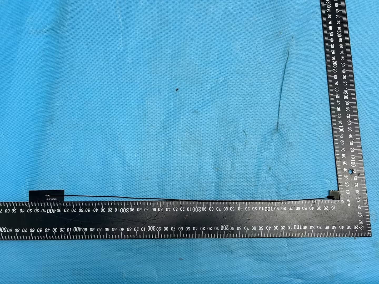
2ANCG-M8800DU6
Jun 18, 2026WLAN +BLE USB Module
Equipment Class
NII - Unlicensed National Information Infrastructure TX
2ANCG-CS63076
Apr 14, 2026BLE Low Engergy Module
Equipment Class
DTS - Digital Transmission System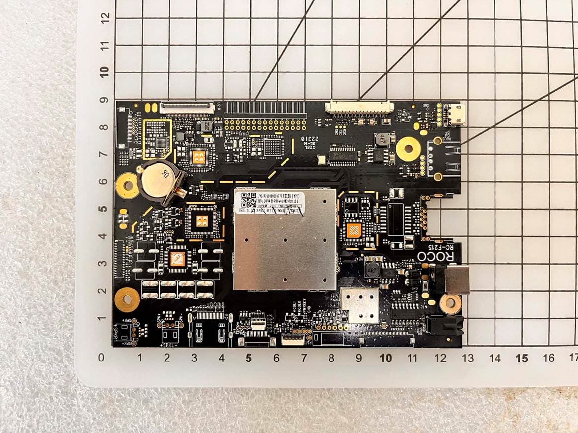
2ANCG-F215U
Aug 03, 2023Function board
Equipment Class
DTS - Digital Transmission System
2ANCG-WTM1C10
Jul 12, 2023WTM1C10
Equipment Class
DCD - Part 15 Low Power Transmitter Below 1705 kHz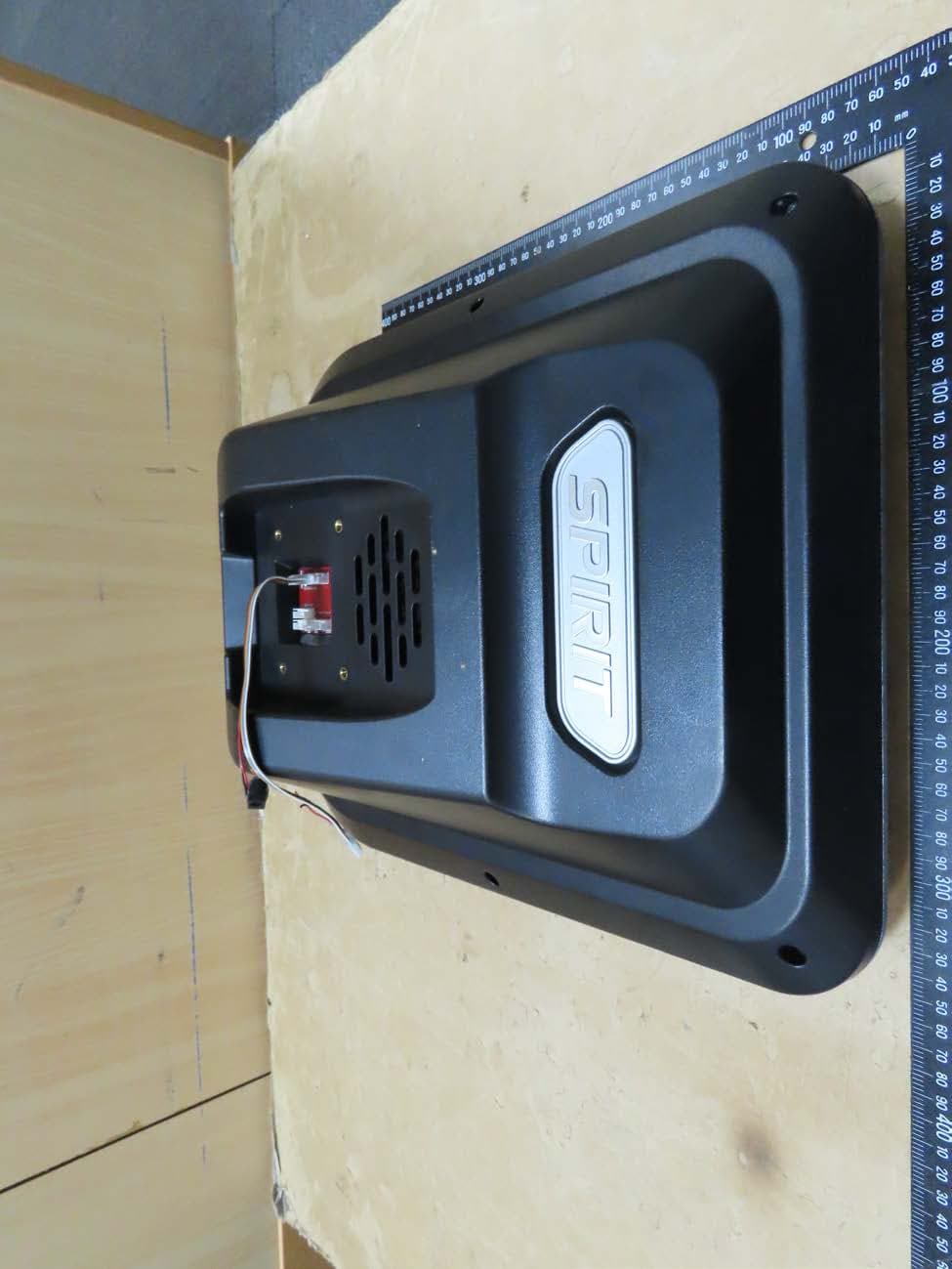
2ANCG-ATA10001
Jul 21, 2021TFT Electronic Meter
Equipment Class
NII - Unlicensed National Information Infrastructure TX