2APJZ-CW006Remote Controller
Polygroup Trading Limited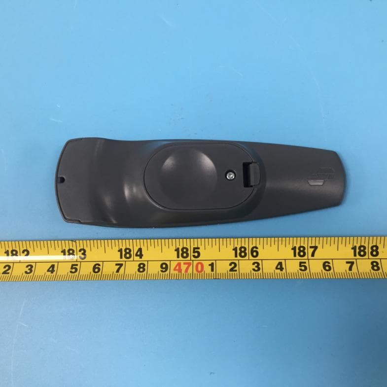
Click to zoom
Application Details
- Equipment Class
- DSC - Part 15 Security/Remote Control Transmitter
- Date of Grant
- May 25, 2020
- Application Purpose
- Original Equipment
- Date of Application
- May 25, 2020
- Equipment Note
- Remote Controller
- Frequency Range
- 433.97000000 - 433.97000000
- Company
- Polygroup Trading Limited
- Country
- China
Documents & Files
Document Text
Text extracted from the exhibit documents filed with the FCC. Open a document above to read the original.
Users Manual
*Electrical Rating For The Tree (For Indoor Use Only) Input: 120VAC, 60Hz, 0.38A Output: 29V DC 0.621A Fig. B - Tree and Light Assembly Tree top Section 2 Section 1 Top view Side view Fig. C MODEL #: TG76M2AGMD11 1. Before you start to assemble your tree, choose an appropriate location near a wall outlet. 2. Assemble the tree stand and place on a level surface. (See Fig. A) TREE ASSEMBLY INSTRUCTIONS 1 NEED HELP? DO NOT RETURN TO STORE. PLEASE VISIT US AT: www.polygroupstore.com OR 1-888-919-0070 Fig. A - Tree Stand Assembly Unfold the legs and lay the stand in a flat area. Then slide the locking disc downward and snap into place. Please scan code to learn how to shape and set up your tree Congratulations on purchasing your new tree from Polygroup®! This tree comes with Quick Set® technology - allowing you to set up your tree and light it up in minutes! Carefully follow the instructions below on how to quickly and easily set up your new tree. 3. Each tree section is numbered with a sticker. Please identify all sections before assembling. 4. Assemble the tree from bottom to the top. Start with the bottom section and remove the protective cap before inserting into the assembled stand. Make sure the pole is firmly inserted and secured into the stand. 5. Continue by inserting the upper tree section(s) to the lower section(s) until inserting the tree top. 6. Allow branches to fall into place or gently pull up and out. When adjusting branches, be sure that all wires are free of branch hinges. 7. Insert green label extension cord into adapter and adapter insert into the wall outlet (See Fig. B), your entire tree should now be lit. 8. Begin to shape the branches and tips working from the bottom to the top. Start with tips farthest from the pole and fan out one to the right, one to the left and one at the center of the main stem. (See Fig. C) Adapter To Be Plugged Into Wall Outlet Insert Green Label Plug into Adapter Align both arrows in a straight line before sliding down to insert Open the cap cover Do Not Tamper Internal Parts 2 TROUBLESHOOTING TIPS For Pre-lit Trees, If The Tree Does Not Illuminate 1. Please check to make sure that all plugs are properly connected and the adapter is plugged into the wall outlet. 2. Turning the poles gently to make sure pole to pole are connected into place. 3. Check for loose connection between light string plugs and extension cords. 1. Extra hinge pins are included for repairing the hinges. Place the branch into the slot of the bracket. 2. Insert a new hinge pin through the hole and secure using the retainer washer.(See Fig. E) Loose Hinge Pin Fig.E 9. After shaping the entire tree following the previous step, slightly upsweep all branch tips for a uniform look. Shift branches to fill any gaps. Your Christmas tree is now complete and ready to be decorated. STORAGE INSTRUCTIONS 1. Unplug the power adapter from the wall outlet first and then remove all ornaments and decorations. 2. Disassemble the tree from the top to the bottom. Start with the tree top and gently lift straight up to remove from section below and fold all branches toward the pole. 3. Continue by gently lifting straight up each section(s) from the section below and fold all branches toward the pole until the bottom section is removed from the tree stand. Cover the cap on the poles to avoid damaging the internal parts. (See Fig. D) 4. Carefully place all tree sections into shipping box and tape it shut. 5. When not in use, please store your tree in a cool, dry place away from sunlight. Exposing your tree to excessive heat or humidity may damage your tree. Fig. D HOW TO USE THE DUAL COLOR LIGHT CONTROLLER AND REMOTE CONTROL: A selector button B selector button Press A selector button on the “Dual Color Light Controller” or “Remote Controller” to select among: (1) CLEAR AND MULTI-COLOR ALTERNATING; (2) CLEAR LIGHTS; (3) MULTI LIGHTS Press B selector button on the “Dual Color Light Controller” or “Remote Controller” to select among: (1) COMBO (2) STEADY (3) SHIMMER (4) STARFIELD (5) CHASER (6)LIGHTNING (7) STACKER REMOTE CONTROL INSTRUCTIONS Remove the insulation tab of the remote control. Insulation Tab WARNING: This product may potentially trigger seizures for people with photosensitive epilepsy when using the motion effect light modes. CAUTION: To reduce the risk of fire and electric shock: a) Use only the power supply that was provided with this product. Using a different adapter will damage the lights and may cause fire, or electrical shock hazards. b) Do not install on trees having needles, leaves or branch covering of metal or materials which look like metal. c) Do not mount or support strings in a manner that can cut or damage wire insulation. 3 1. Loosen the screw of the battery cover with a screwdriver (not included). Battery Replacement 2. Replace the used battery with a new CR2032 button cell battery (not included). Make sure that the battery is installed with the correct polarity (+ and -). 3. Retighten the screw to close and secure the battery cover. WARNING 1. This remote controller is powered by a lithium battery. Due to their small size, lithium batteries can easily be swallowed by children. Ingestion of such batteries has been known to cause death. 2. This is a lithium battery which if swallowed has been known to cause death. 3. SMALL PARTS, KEEP BATTERIES OUT OF REACH OF CHILDREN. 4. Do not expose the remote controller to moisture. 5. Remove batteries when not used for an extended period of time, or when depleted. 6. Dispose of used batteries properly. 7. Use only CR2032 batteries for the remote controller. 8. Clean the battery contact surfaces gently prior to battery installation. 9. DO NOT DISPOSE OF BATTERIES IN FIRE. BATTERIES MAY EXPLODE OR LEAK. 4 CUSTOMER SERVICE FOR CHRISTMAS TREES For any questions, assistance, or missing parts, Do Not Return To Place Of Purchase. Please contact us at 1-888-919-0070 or visit our website at www.polygroupstore.com. One of our customer serv…
Text truncated - open the document above for the full version.
Cover Letter(s)
Polygroup Trading Limited ADD: Unit 606,Fairmont House, 8 Cotton Tree Drive, Central, Hong Kong, China Tel: (852) 3583 2222 E-mail: [email protected] FCC Authorization 2020-05-21 FEDERAL COMMUNICATIONS COMMISSIONS Authorization and Evaluation Division 7435 Oakland Mills Road Columbia, MD 21046 Subject: Agent Authorization To whom it may concern: We, Polygroup Trading Limited, Hereby authorizes Bay Area Compliance Laboratories Corp to act on its behalf in all matters relating to application for Equipment authorization, including the signing of all documents relating to these matters. All acts carried out by Bay Area Compliance Laboratories Corp on our behalf shall have the same effect as our own action. We, the undersigned, hereby certify that we are not subject to a denial of federal benefits, that includes FCC benefits, pursuant to Section 5301 of the Anti-Drug Abuse Act of 1988, 21 U.S.C. 862. This authorization is valid until further written notice from the applicant. Sincerely Yours, Signature: Print Name: Daniel.Liu Title: Compliance Manager QA-FR-170-B
Cover Letter(s)
Polygroup Trading Limited ADD: Unit 606,Fairmont House, 8 Cotton Tree Drive, Central, Hong Kong, China Tel: (852) 3583 2222 E-mail: [email protected] FCC Confidential Authorization Date: 2020-05-21 FEDERAL COMMUNICATIONS COMMISSIONS Authorization and Evaluation Division 7435 Oakland Mills Road Columbia, MD 21046 Subject: Confidentiality Request regarding application for certification of FCC ID: 2APJZ-CW006 In accordance with Sections 0.457 and 0.459 of the Commission’s Rules, Polygroup Trading Limited hereby requests long-term confidential treatment of information accompanying this application as outlined below: Block Diagram Schematics Operation Description The above materials contain proprietary and confidential information not customarily released to the public. The public disclosure of these materials provides unjustified benefits to its competitors in the market. Sincerely Yours, Signature: Print Name: Daniel Liu Title: Compliance Manager
External Photos
EXHIBIT B - EUT EXTERNAL PHOTOGRAPHS
ID Label/Location Info
EXHIBIT A - FCC ID LABEL AND LOCATION FCC ID Label FCC ID Label Location Information The label shown shall be permanently affixed at a conspicuous location on the device and be readily visible to the user at the time purchase (Labeling requirements per 2.925)
Internal Photos
EXHIBIT C - EUT INTERNAL PHOTOGRAPHS Antenna
Test Report
Note: This report must not be used by the customer to claim product certification, approval, or endorsement by A2LA* or any agency of the Federal Government. This report may contain data that are not covered by the A2LA accreditation and are marked with an asterisk “★”. BACL is not responsible for the authenticity of any test data provided by the applicant. Data included from the applicant that may affect test results are marked with an asterisk ’*’. Customer model name, addresses, names, trademarks etc. are not considered data. This report cannot be reproduced except in full, without prior written approval of the Company. Unless otherwise stated the results shown in this test report refer only to the sample(s) tested. This report is valid only with a valid digital signature. The digital signature may be available only under the Adobe software above version 7.0. FCC PART 15.231 TEST REPORT For Polygroup Trading Limited Unit 606, Fairmont House, 8 Cotton Tree Drive, Central, Hong Kong FCC ID: 2APJZ-CW006 R e p o r t T y p e : O r i gi n a l R e p o r t P r o d u c t T y p e : R e mo t e c o n t r o l l e r Report Number: RSZ200113811-00 Report Date: 2020-04-28 Reviewed By: Jimmy Xiao RF Engineer Prepared By: Bay Area Compliance Laboratories Corp. (Shenzhen) 6/F., West Wing, Third Phase of Wanli Industrial Building, Shihua Road, Futian Free Trade Zone, Shenzhen, Guangdong, China Tel: +86-755-33320018 Fax: +86-755-33320008 www.baclcorp.com.cn Bay Area Compliance Laboratories Corp. (Shenzhen) Report No.: RSZ200113811-00 FCC Part 15.231 Page 2 of 17 TABLE OF CONTENTS GENERAL INFORMATION ....................................................................................................................................... 3 PRODUCT DESCRIPTION FOR EQUIPMENT UNDER TEST (EUT) ..................................................................................... 3 OBJECTIVE ................................................................................................................................................................... 3 RELATED SUBMITTAL(S)/GRANT(S) ............................................................................................................................. 3 TEST METHODOLOGY .................................................................................................................................................. 3 MEASUREMENT UNCERTAINTY .................................................................................................................................... 4 SYSTEM TEST CONFIGURATION .......................................................................................................................... 5 JUSTIFICATION ............................................................................................................................................................. 5 SPECIAL ACCESSORIES ................................................................................................................................................. 5 EQUIPMENT MODIFICATIONS ....................................................................................................................................... 5 SUPPORT EQUIPMENT LIST AND DETAILS .................................................................................................................... 5 EXTERNAL I/O CABLE.................................................................................................................................................. 5 BLOCK DIAGRAM OF TEST SETUP ................................................................................................................................ 5 SUMMARY OF TEST RESULTS ............................................................................................................................... 6 TEST EQUIPMENT LIST AND DETAILS ............................................................................................................... 7 FCC §15.203 - ANTENNA REQUIREMENT ............................................................................................................. 8 APPLICABLE STANDARD .............................................................................................................................................. 8 ANTENNA CONNECTOR CONSTRUCTION ...................................................................................................................... 8 FCC §15.205, §15.209, §15.231 (B) - RADIATED EMISSIONS ............................................................................... 9 APPLICABLE STANDARD .............................................................................................................................................. 9 EUT SETUP .................................................................................................................................................................. 9 EMI TEST RECEIVER SETUP ....................................................................................................................................... 10 TEST PROCEDURE ...................................................................................................................................................... 10 CORRECTED AMPLITUDE & MARGIN CALCULATION ................................................................................................. 11 TEST RESULTS SUMMARY .......................................................................................................................................... 11 TEST DATA ................................................................................................................................................................ 11 FCC §15.231(A) (1) - DEACTIVATION TESTING................................................................................................. 15 APPLICABLE STANDARD ...........................................................................................................…
Text truncated - open the document above for the full version.
Test Setup Photos
EXHIBIT D - TEST SETUP PHOTOGRAPHS Radiated Emissions View (Below 1 GHz) Radiated Emissions View (Above 1 GHz)
Contact Information
Applicant
Michael Wang(Compliance manager)
Test Firm
Bay Area Compliance Laboratories Corp. (Shenzhen)Well Wang
[email protected]+86 (0) 755 33320018
Technical Specifications
| # | Rule Parts | Frequency Range | Power Output |
|---|---|---|---|
| 1 | 15.231 | 433.97 MHz - 433.97 MHz | - |
Other Applications from Polygroup Trading Limited
2APJZ-PDR03424VR
Apr 10, 2022Controller
Equipment Class
DSS - Part 15 Spread Spectrum Transmitter
2APJZ-TBC003
May 09, 2021Controller
Equipment Class
DSS - Part 15 Spread Spectrum Transmitter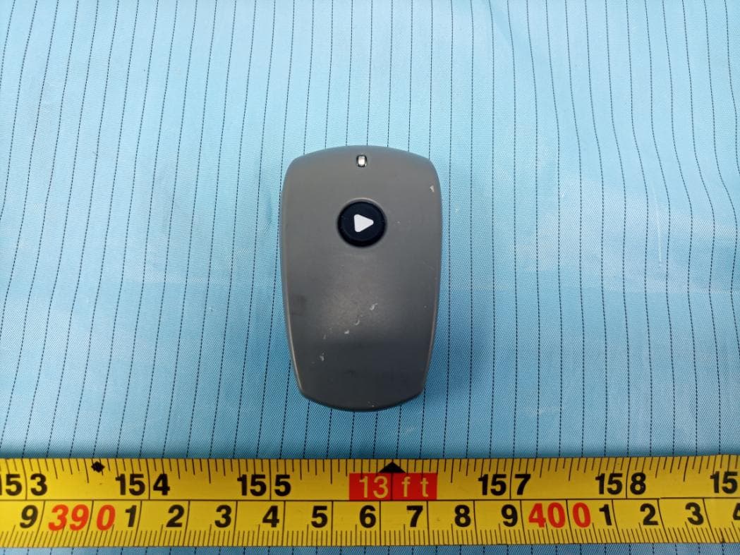
2APJZ-CW005
Nov 03, 2020Remote Controller
Equipment Class
DSC - Part 15 Security/Remote Control Transmitter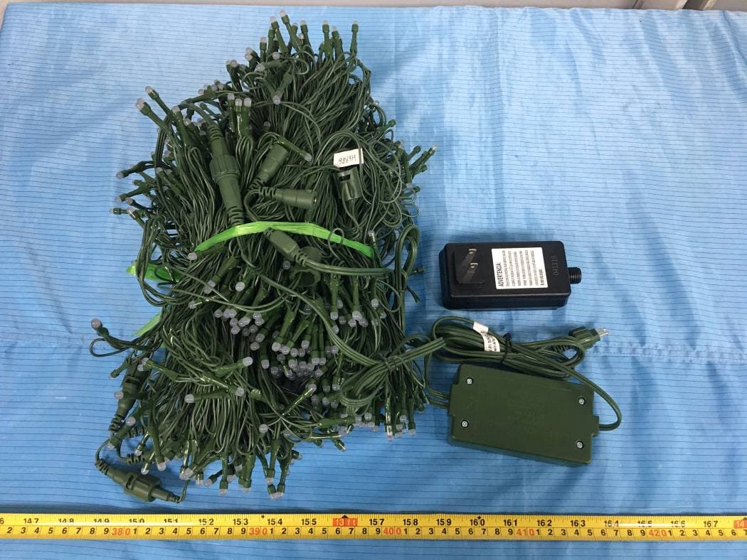
2APJZ-TW200117R
Jun 04, 2020Controller
Equipment Class
DTS - Digital Transmission System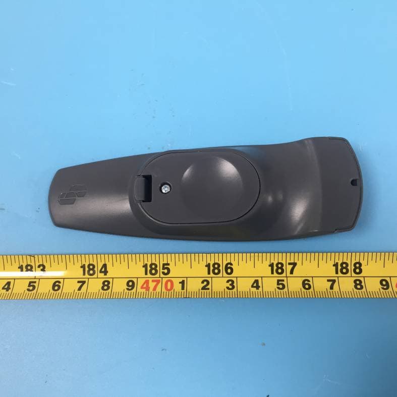
2APJZ-CW007
May 25, 2020Remote Controller
Equipment Class
DSC - Part 15 Security/Remote Control Transmitter