2APQV-BHS120USBLE transceiver
Brilliant Home Technology Inc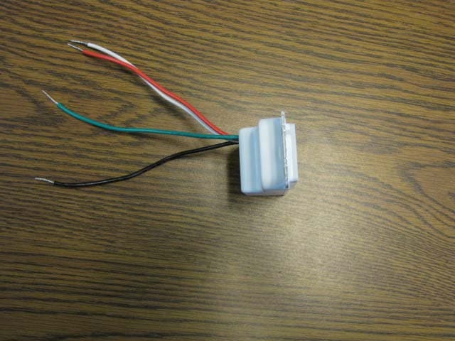
Click to zoom
Application Details
- Equipment Class
- DTS - Digital Transmission System
- Date of Grant
- Jun 18, 2020
- Application Purpose
- Original Equipment
- Date of Application
- Jun 14, 2020
- Equipment Note
- BLE transceiver
- Frequency Range
- 2402.00000000 - 2480.00000000
- Country
- United States
Documents & Files
Document Text
Text extracted from the exhibit documents filed with the FCC. Open a document above to read the original.
Users Manual
Wire nuts x5 Dimmer Switch Screws Before you beginInstall using the Brilliant app In the boxInstallation labels Troubleshooting The Brilliant Smart Home System Works withLegalLegal Step 1 Step 2 Download the app Download the Brilliant app from the Apple Store or Google Play Store. Follow installation guide in app Receive step-by-step installation instructions using the Brilliant app. Here’s what you need to know before you expand your Brilliant Smart Home System with the Brilliant Dimmer Switch. REQUIREMENTS Brilliant Control: At least one Brilliant Control must be installed for Brilliant Switch to work. Neutral & Ground Wires: Use the Brilliant app to confirm that your electrical wiring is supported. Electrical: - 120V AC - up to 500W incandescent/halogen - up to 200W LED/CFL - Magnetic low voltage (MLV) lighting not supported. Tools: Non-contact voltage detector, Philips screwdriver, standard screwdriver, pliers Want to learn more about what you can do with your Brilliant Dimmer Switch? Visit www.brilliant.tech & more Need additional help? http://support.brilliant.tech LED Status Indicator White Blinking: Powered on and ready to be set up White Solid: Successfully set up and connected to your home Blue Blinking: Error detected, reset Dimmer Switch Reset Instructions Quick Start Guide NOTE: This device complies with part 15 of the FCC Rules. Operation is subject to the following two conditions: (1) This device may not cause harmful interference, and (2) this device must acceptany interference received, including interference that may cause undesired operation. These limits are designed to provide reasonable protection against harmful interference in a residential installation. This equipment generates, uses and can radiate radio frequency energy and, if not installed and used in accordance with the instructions, may cause harmful interference to radio communications. However, there is no guarantee that interference will not occur in a particular installation. If this equipment does cause harmful interference to radio or television reception, which can be determined by turning the equipment o and on, the user is encouraged to try to correct the interference by one or more of the following measures: —Reorient or relocate the receiving antenna. —Increase the separation between the equipment and receiver. —Connect the equipment into an outlet on a circuit di erent from that to which the receiver is connected. —Consult the dealer or an experienced radio/TV technician for help. FCC CAUTION Changes or modifications not expressly approved by the party responsible for compliance could void the user’s authority to operate the equipment. This transmitter must not be co-located or operated in conjunction with any other antenna or transmitter. This device contains licence-exempt transmitter(s)/re- ceiver(s) that comply with Innovation, Science and Economic Development Canada’s licence-exempt RSS(s). Operation is subject to the following two conditions: 1.This device may not cause interference. 2. This device must accept any interference, including interference that may cause undesired operation of the device. L’émetteur/récepteur exempt de licence contenu dans le présent appareil est conforme aux CNR d’Innovation, Sciences et Développement économique Canada applicables aux appareils radio exempts de licence. L’exploitation est autorisée aux deux conditions suivantes : 1. L’appareil ne doit pas produire de brouillage; 2. L’appareil doit accepter tout brouillage radioélectrique subi, même si le brouillage est susceptible d’en comprom- ettre le fonctionnement. Wire labels Gang box labels 1GroundGround 1 1NeutralNeutral 1 1LineLine 1 1TravelerTraveler 1 1LoadLoad 1 Load Pull out Safety Disconnect (clear plastic tab over LED) until LED turns o . Push in Safety Disconnect until LED turns on. Place your finger on Touch Plate and hold for 6-10 seconds until LED blinks white. Transform any house or apartment into an easy-to-use smart home. 1 2 3 SMART DIMMER SWITCH Features Motion Sensor Set up with app Slider Dim lights: Swipe up/down Touch Plate On/O : Tap anywhere Activate scene: Double tap LED Set up with app Safety Disconnect Reset Dimmer Switch Home Control required Dimmer Switch Mobile AppSmart Plug 510-00008 REV 2 Line Pantone 314Pantone 1495 Front 123456 789101112 Back
Cover Letter(s)
April 16, 2020 Federal Communications Commission Authorization and Evaluation Division 7435 Oakland Mills Road Columbia, MD FCC Agent Authorization Letter Applicant Brilliant Home Technology, Inc Model Name BHS120US-WH1 FCC ID 2APQV-BHS120US We, the undersigned, hereby authorize Atlas Compliance & Engineering, Inc. to act on our behalf in all manners relating to application for equipment authorization, including signing of all documents relating to these matters. Any and all acts carried out by Atlas Compliance & Engineering, Inc. on our behalf shall have the same effect as acts of our own. We, the undersigned, hereby certify that we are not subject to a denial of federal benefits, that includes FCC benefits, pursuant to Section 5301 of the Anti-Drug Abuse Act of 1988, 21 U.S.C. 853(a). This authorization is valid until further written notice from the applicant. Sincerely, Brian Cardanha VP, Hardware Engineering Brilliant Home Technology, Inc 155 Bovet Rd, Suite 500 San Mateo, CA 94402, USA [email protected]
ID Label/Location Info
Input: 120VAC, 60Hz Incandescent: 500W CFL/LED: 200W GROUND LOAD NEUTRAL LINE FCC ID: 2APQV-BHS120US IC: 23875-BHS120US Designed In California Assembled In USA For Indoor Use Only Home Automation Equipment S/N: XXXXXXXXXX Model BHS120US-AL1 Input: 120VAC, 60Hz Incandescent: 500W CFL/LED: 200W GROUND LOAD NEUTRAL LINE S/N: XXXXXXXXXX FCC ID: 2APQV-BHS120US IC: 23875-BHS120US Model BHS120US-BK1 Designed In California Assembled In USA For Indoor Use Only Home Automation Equipment Input: 120VAC, 60Hz Incandescent: 500W CFL/LED: 200W GROUND LOAD NEUTRAL LINE S/N: XXXXXXXXXX FCC ID: 2APQV-BHS120US IC: 23875-BHS120US Model BHS120US-CG1 Designed In California Assembled In USA For Indoor Use Only Home Automation Equipment Input: 120VAC, 60Hz Incandescent: 500W CFL/LED: 200W GROUND LOAD NEUTRAL LINE S/N: XXXXXXXXXX FCC ID: 2APQV-BHS120US IC: 23875-BHS120US Model BHS120US-WH1 Designed In California Assembled In USA For Indoor Use Only Home Automation Equipment 0.90 0.31 1.23 0.98 R0.03 350-00017 LABEL, SWITCH FAI 61 FAI 62 FAI 64 FAI 63 FAI 67 FAI 68 FAI 66 FAI 65 FAI 73 FAI 74 FAI 76 FAI 75 FAI 71 FAI 72 FAI 70 FAI 69 FAI 53 FAI 54 FAI 56 FAI 55 FAI 59 FAI 60 FAI 58 FAI 57 FAI 52 FAI 51 FAI 93 FAI 94 FAI 96 FAI 95 FAI 99 FAI 100 FAI 98 FAI 97 FAI 89 FAI 90 FAI 92 FAI 91 FAI 103 FAI 104 FAI 102 FAI 101 FAI 109 FAI 110 FAI 112 FAI 111 FAI 107 FAI 108 FAI 106 FAI 105 FAI 81 FAI 82 FAI 84 FAI 83 FAI 87 FAI 88 FAI 86 FAI 85 FAI 77 FAI 78 FAI 80 FAI 79 FAI 46 FAI 48 FAI 47 FAI 50 FAI 49 SPC AB SPC AC SPC Y SPC X SPC W SPC Z SPC V SPC AA SPC U SPC L SPC R SPC K SPC M SPC Q SPC N SPC O SPC P SPC T SPC S FAI 34 FAI 35 FAI 36 FAI 31 FAI 32 FAI 33 FAI 42 FAI 41 FAI 40 FAI 45 FAI 44 FAI 43 FAI 37 FAI 38 FAI 39 SPC I SPC J FAI 28 FAI 29 FAI 30 FAI 26 FAI 27 FAI 25 FAI 13 FAI 14 FAI 15 FAI 18 FAI 17 FAI 16 FAI 22 FAI 23 FAI 24 FAI 21 FAI 20 FAI 19 FAI 7 FAI 8 FAI 9 FAI 12 FAI 11 FAI 10 SPC F SPC E SPC D SPC G SPC C SPC H AA BB 4 4 3 3 2 2 1 1 SEE NOTES ASM, SWITCH LABEL POSITION DO NOT SCALE DRAWING SHEET 1 OF 1 2020.03.13 VZ UNLESS OTHERWISE SPECIFIED: SCALE: 1:5 WEIGHT: REV DWG. NO. B SIZE TITLE: NAME DATE COMMENTS: Q.A. MFG APPR. ENG APPR. CHECKED DRAWN SEE NOTES FINISH MATERIAL INTERPRET GEOMETRIC TOLERANCING PER: ASME Y14.5- 2009 DIMENSIONS ARE IN MM TOLERANCES: TWO PLACE DECIMAL 0.10 THREE PLACE DECIMAL 0.050 APPLICATION USED ON NEXT ASSY PROPRIETARY AND CONFIDENTIAL THE INFORMATION CONTAINED IN THIS DRAWING IS THE SOLE PROPERTY OF BRILLIANT HOME TECHNOLOGY. ANY REPRODUCTION IN PART OR AS A WHOLE WITHOUT THE WRITTEN PERMISSION OF BRILLIANT HOME TECHNOLOGY IS PROHIBITED.
RF Exposure Info
FCC SAR Exemption Calculation The Brilliant Smart Dimmer Switch is mounted in a user’s wall in a standard electrical box, just like a traditional light switch. A user can control the load connected to their Smart Dimmer Switch by touching the surface of the switch. When a user touches the switch, the antenna will transmit. The closest distance is determined from the closest point on the surface that a user can touch to the transmitting antenna on the PCB. In order to determine the separation distance between the antenna and the outer surface of the device, the plastic enclosure, pressure sensitive adhesive (PSA), and the PCB need to be taken into account. The thickness of the plastic enclosure is 4.55mm. A PSA of thickness 0.25mm is applied, and then the PCB of thickness 1.1mm is added. The PSA allows the PCB to be adhered to the plastic enclosure. Given these values, the distance between the outer surface and antenna is a total of 5.9mm. Considering that the PSA will be compressed, the distance will be closer to 5.75mm. In the worst case of no PSA being added, the smallest separation distance will be 5.65mm. Using the worst-case separation distance and the equation described in KDB 447498 D01 General RF Exposure Guidance v06 4.3.1 (shown below), we see that the Smart Dimmer Switch is below the limit. Frequency = 2.44GHz Max Power of Channel = 4.05dBm = 2.5409727055mW Minimum Distance = 5.65mm Power and distance are rounded to the nearest mW and mm before calculation. The result is rounded to one decimal place for comparison. [(max. power of channel, including tune-up tolerance, mW) / (min. test separation distance, mm)] · [√f(GHz)] ≤ 3.0 for 1-g SAR, and ≤ 7.5 for 10-g extremity SAR ( 3푚푊 6푚푚 )× √ 2.44 퐺퐻푧=0.8 0.8 ≤ 3.0 for 1-g SAR, and ≤ 7.5 for 10-g
Test Report
1950BRNsw_fcc247 C8 Page 1 of 78 Atlas Compliance & Engineering, Inc. 1792 Little Orchard Street San Jose, CA 95125 Phone 408.971.9743 Fax 408-971-9783 Web www.atlasce.com .......... Atlas Compliance & Engineering, Inc. FCC Test Report FCC CFR 47 Part 15.207, 15.209 and 15.247 COMPLIANCE Brilliant Home Technology, Inc. 155 Bovet Road Suite 500 San Mateo, CA 94402, USA Product: Brilliant Smart Dimmer Switch Model: BHS120US-WH1 FCC ID: 2APQV-BHS120US Test Report Number: 1950BRNsw_fcc247 Date of Report: February 13, 2020 This report contains 78 pages and may be reproduced in full only. Partial reproduction may only be done with the written consent of Atlas Compliance & Engineering, Inc. Testing Cert #1007.01 1950BRNsw_fcc247 C8 Page 2 of 78 Atlas Compliance & Engineering, Inc. 1792 Little Orchard Street San Jose, CA 95125 Phone 408.971.9743 Fax 408-971-9783 Web www.atlasce.com Table of Contents Table of Contents ................................................................................................................................................... 2 General Information ............................................................................................................................................... 5 Test Equipment ....................................................................................................................................................... 6 Test Configuration .................................................................................................................................................. 7 Operational Description:..................................................................................................................................... 7 EUT Description / Note: ..................................................................................................................................... 8 EUT Support Program ........................................................................................................................................ 8 EUT Modifications for Compliance ................................................................................................................... 8 Measurement Uncertainty................................................................................................................................... 8 EUT Support Devices ......................................................................................................................................... 9 I/O Ports and Cables ........................................................................................................................................... 9 Equipment Under Test .......................................................................................................................................... 10 Equipment Block Diagram ................................................................................................................................... 12 Test Methods for Emissions ............................................................................................................................. 13 Conducted Emission Testing ............................................................................................................................ 13 Temperature and Humidity ............................................................................................................................... 14 Sample Calculations ......................................................................................................................................... 14 Test setup for conducted measurements ........................................................................................................... 15 Minimum -6dB Bandwidth ............................................................................................................................... 16 Peak Power Spectral Density ............................................................................................................................ 18 Maximum Peak Output Power ......................................................................................................................... 20 Equivalent Isotropically Radiated Power ......................................................................................................... 23 Unwanted Emissions ........................................................................................................................................ 24 Occupied Bandwidth (99% emissions bandwidth) ........................................................................................... 41 AC Power Line Conducted Emissions ............................................................................................................. 44 AC Power Line Conducted Data for Line ........................................................................................................ 45 AC Power Line Conducted Data for Neutral .................................................................................................... 46 Transmitter Emission ........................................................................................................................................ 47 Report of Measurements Radiated Data ........................................................................................................... 47 Radiated Data ................................................................................................................................................... 48 Frequency Stability ........................................................................................................................................... 76 COMPLIANCE VERIFICATION REPORT ....................................................................................................... 78 Table 1 – Support Equipment Used For Test ...................................................…
Text truncated - open the document above for the full version.
Contact Information
Applicant
Brian Cardanha(VP, Hardware Engineering)
Test Firm
ATLAS Compliance & Engineering, Inc.Bruce Smith
Technical Specifications
| # | Rule Parts | Frequency Range | Power Output |
|---|---|---|---|
| 1 | 15C | 2.40 GHz - 2.48 GHz | 2.50 mW |
Other Applications from Brilliant Home Technology Inc
2APQV-BCPUSMG
Apr 17, 2024Brilliant Control 4-Switch Panel
Equipment Class
DTS - Digital Transmission System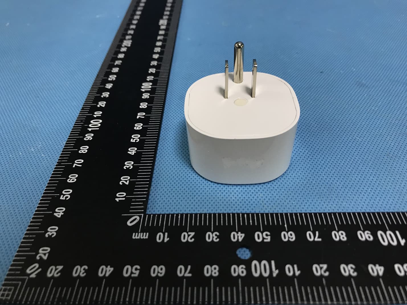
2APQV-BHP120
Apr 08, 2020Smart Plug
Equipment Class
DTS - Digital Transmission System