2APUQW8298 Android Tablet
Hunan Greatwall Computer System Co.,Ltd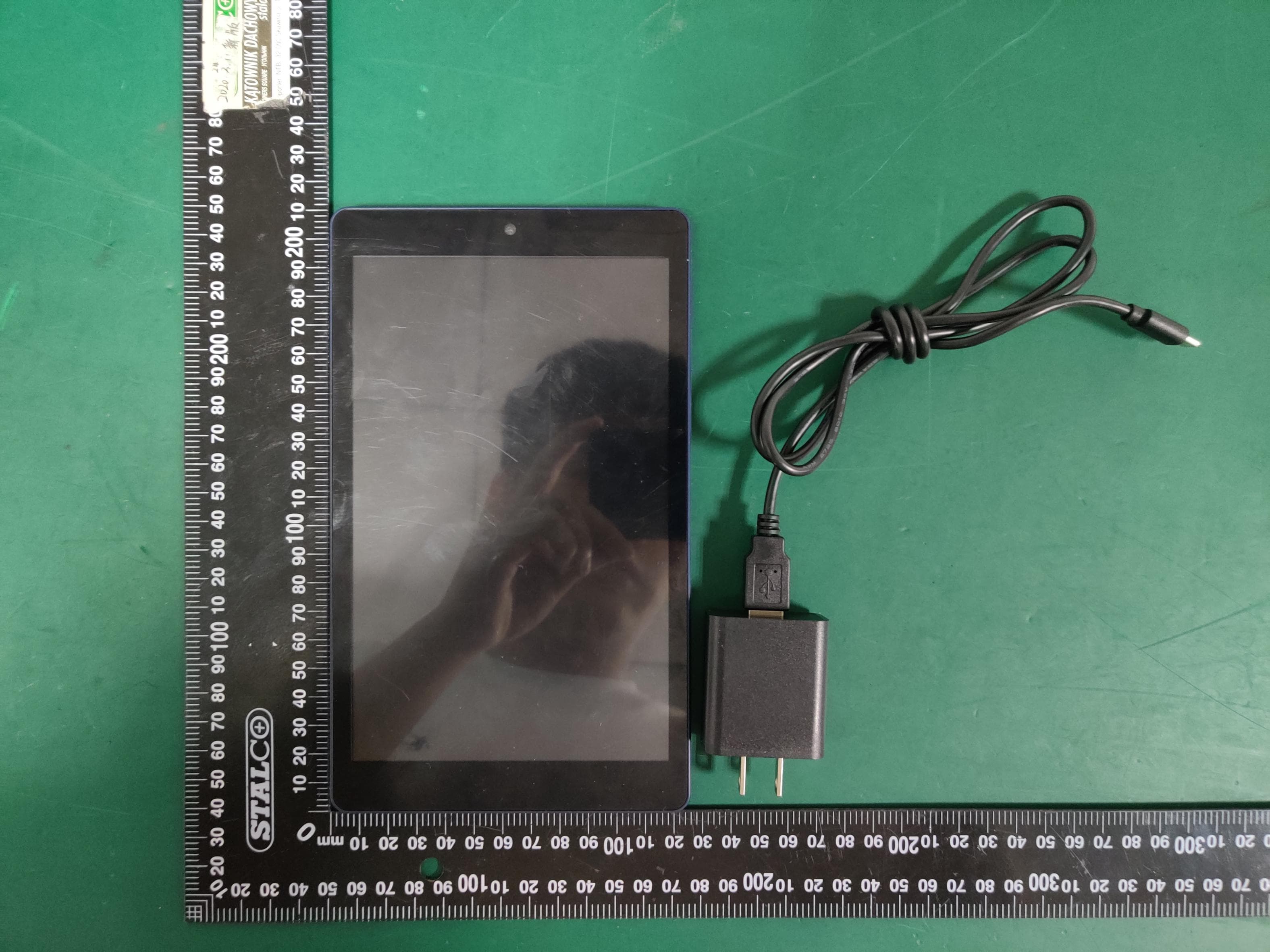
Click to zoom
Application Details
- Equipment Class
- DTS - Digital Transmission System
- Date of Grant
- Jun 08, 2020
- Application Purpose
- Original Equipment
- Date of Application
- Jun 08, 2020
- Equipment Note
- 8 Android Tablet
- Frequency Range
- 2412.00000000 - 2462.00000000
- Country
- China
Documents & Files
Document Text
Text extracted from the exhibit documents filed with the FCC. Open a document above to read the original.
Users Manual
8“Tablet Model:100011885 PRODUCT GUIDE We ‘d love to hear from you. Scan with your Walmart app and let us know what you think. May 12, 2020_V1 648 1 1 3 1 3 1 1 3 0 Introduction Thank you for purchasing the Android 10(Go edition) tablet with Google Play. Featuring a fast and responsive quad core processor, this tablet is perfect for accomplishing everyday tasks, streaming music and movies, taking photos, checking emails, and engaging with social media. The tablet o ers 32GB of internal storage, Bluetooth connectivity, Micro SD slot for up to 128GB of additional storage, on-the-go productivity services. The following information will help you get the most out of your tablet. What You Should Know to Ensure Best Performance: Charge the battery completely before first use. While updates download in the background, tablet performance can be a ected until completed. Close unused applications. Open apps that run in the background will a ect overall performance. Battery Consumption: Play times on a fully charged battery will vary depending on your display settings, apps that remain open, and internet use (e.g.,streaming video content). It is recommended to use a tablet screen protector and tablet case to protect the tablets. 2 3 In The Box USB-C cable size:61*41*24mm Input: 100-240V~50/60Hz,0.3A Output:5.0V 2.0A Charger 8" tabletUser Manual 8“Tablet Quick Start Guide Quick Start Guide 8“Tablet Model:100011885 PRODUCT GUIDE We ‘d love to hear from you. Scan with your Walmart app and let us know what you think. May 12, 2020_V1 648 1 1 3 1 3 1 1 3 0 4 1. Camera (Rear) 2. Reset 3. Power On/o 4. Volume Control 5. USB-C Port 6. Micro SD Slot 7. Earphone 8. Speaker 9. Camera (Front) 5 Starting Your Tablet 1. Press and hold the Power button for 3~4 seconds. (If your tablet does not turn on, or instructs you to "Connect your charger" , connect the AC adapter and charge the unit.) 2. At the Start-up screen, swipe up from the bottom of the screen to unlock. 3. Once you' ve arrived at the Home screen, you can begin using your tablet. Home Screen At-a-Glance 6 1. Status Bar 2. Search Box 3. Walmart App Suite 4. Go Back 5. Home 6. Recents 7 Using the Cameras Tap on the Camera lcon 1.Switch Cameras (Front/Rear) 2.Camera Settings 3.Recent Photo 4.Take Photo 8 Tablet Updates To ensure the tablet runs smoothly it is recommended to perform periodic system software updates, especially during initial set up of the tablet. You may receive notifications (on the Lock screen) from time to time that software updates are available. Tap the notification to be directed to the update. Other options to access updates: Tap on Settings >About Tablet >Wireless Update. NOTE: To perform an update, you must be connected to WiFi. 9 Google Play Updates The first time you sign on to Google Play Store, updates will automatically start downloading on to the tablet.The download icon will appear in the status bar at the top left of screen. Installing a new application while multiple apps are downloading will reduce tablet speed and performance. After all downloads and updates have been installed, the tablet will resume normal operating performance. To view the progress of downloads working in the background, swipe down from the top edge of the screen. 10 Touching and Typing To select an item on the screen, simply tap it once with your fingertip. Some items may require you to "double-tap”. To type in to a text field (i .e., when inputting your name , or a web address), tap the text field. The on-screen keyboard will appear, and allow you to type the information you wish to enter. Touch and Hold: Keep your finger on an on-screen item until it glows or activates an alternate menu. Drag: Move an App or object by touching and holding the image, then moving it to the destination. Slide: When there are extra "screens" to the side, slide one or more fingers from one side to another. 11 Connecting to the Internet Wireless Router In order to connect to the internet, you will need the following: A wireless router or an access point with a broadband internet connection. The name of your network (SSID), as well as the password or other credentials, if your network is secure. The wireless router must support WiFi 802.11 a/b/g/n/ac connections. Go to SETTINGS > Network & internet > WiFi Tap on WiFi to activate wireless connectivity. The Tablet will scan for available WiFi networks within range. Secured networks will require a password. Once you have successfully entered your information the tablet will remember your settings. 12 Connecting Bluetooth Your Tablet is compatible with Bluetooth capable devices. Once your tablet searches and finds the Bluetooth device, follow on-screen instructions to initiate the pairing of the device with the Tablet. Add or "pair" a Bluetooth compatible device with your Tablet as follows: 1) Turn on the compatible Bluetooth device and make it discoverable. 2) Open the Settings > Connected devices. 3) Tap on Pair new device to view available devices. 13 Charging Your Tablet It is recommended to fully charge the tablet before first use. To charge the tablet, 1) plug the USB cable into the AC adapter, 2) attach the other end to the USB-C input on the tablet, 3) plug the AC adapter into a wall outlet. When the tablet is ON and charging, the battery icon will pulsate. A complete battery charge may take up to 3 hours. It is normal for the tablet to get warm while charging, playing games, or streaming video. Battery life will vary depending on usage. Note: Leave tablet in a well ventilated area while charging. 14 Important Safety Instructions 1.Do not install near any heat sources such as radiators, heat registers, stoves, or other apparatus (including amplifiers) that produce heat. 2.WARNING:Only use attachments/accessories specified or provided by the manufacturer(such as the exclusive supply adapter, battery etc). 3.WARNING:The mains plug should be kept in a state that can be disconnected at anytime to avoid emergency situatio…
Text truncated - open the document above for the full version.
Cover Letter(s)
C526仅)91_)(10_Ed.1 Hunan Greatwall Computer System Co.,Ltd 0仔iαof Engineering Technol og y Federal Communications Co mmission 7 435 Qakland Mills Ro ad Columbia, MD 21046 D ate: 5/ 15/2020 Subject: Request for Confidentiality FC C ID: 2A矶JQW829 To Whom It May Concern, Pursuant to the provisions of sections 0.457 and 0.459 of Commission's rules ( 47CFR0.457, 0.459), we are requ础ing the Commission to withhold the following a阳由ment(s) as ro nfidential document from public disclosure. Exhlb阳 Lo『可-Term9、ort-Term Confidentialitv Confi出ntialitv ID Label/Location No No Attes国tlon Statement No No Extemal Photos No 口j Block DiaQram 国1 DJ Schematics 凶iDJ Test Reoort No N。 Test Setuo Photos No [J) User's Mam且l UJ UJ Inter旧l Photos UJ 口j Pa『也ListI Tune Uo UJ 口j RF E咱OsureInfo Ul DJ Ooerational Descriotion 国1 DJ Cover Letter(sl No No SDRSo耐wareIS副卫ritv Info 因j No Above n回ntion创documentcontains detail创町stemand equip町、entdescription are considered as proprietary information in operation of the equipment. The public disclosure of above documents might be harn向Ito our company and would give competitor an unfair advantage in the market. It is our understanding时,atall measurement test repor饵,FCCID label format and correspondent during cer tification review process臼nnotbe grant刨出confidential documents and those information will民availablefor public rev陪wonce the grant of equip町、entauthorization is issued. Sincerely , 仰ture:ι) Name:Kelvin Wang Title:Manager
External Photos
FCCID:2APUQW829 ESTTechnologyCo.,LtdReportNo.ESTE-R2004079Page1of4 ExternalPhotos M/N:100011885 FCCID:2APUQW829 ESTTechnologyCo.,LtdReportNo.ESTE-R2004079Page2of4 ExternalPhotos M/N:100011885 FCCID:2APUQW829 ESTTechnologyCo.,LtdReportNo.ESTE-R2004079Page3of4 ExternalPhotos M/N:100011885 FCCID:2APUQW829 ESTTechnologyCo.,LtdReportNo.ESTE-R2004079Page4of4 PowerSupply
Internal Photos
FCCID:2APUQW829 ESTTechnologyCo.,LtdReportNo.ESTE-R2004079Page1of5 InternalPhotos M/N:100011885 FCCID:2APUQW829 ESTTechnologyCo.,LtdReportNo.ESTE-R2004079Page2of5 InternalPhotos M/N:100011885 FCCID:2APUQW829 ESTTechnologyCo.,LtdReportNo.ESTE-R2004079Page3of5 InternalPhotos M/N:100011885 FCCID:2APUQW829 ESTTechnologyCo.,LtdReportNo.ESTE-R2004079Page4of5 InternalPhotos M/N:100011885 FCCID:2APUQW829 ESTTechnologyCo.,LtdReportNo.ESTE-R2004079Page5of5 InternalPhotos M/N:100011885 MainboardModelNo.:MDXC1016G-M22GB<MZ0007HF-DAB1-SM MainboardModelNo.:RS512M32LM4D2BDS-53BT2GB&EMMC32G-TA2832GB
RF Exposure Info
Model: SOL07 Report No.: WTD20X04022492W Page 1 of 65 SAR Report Test Standards: FCC Part 2.1093, ANSI / IEEE C95.1 :2005+A1:2010 ANSI / IEEE C95.3 :2002(R2008) Product Description: 8"Android Tablet Tested Model: 100011885 Report No.: WTD20X04022492W Sample Received Date: 2020-04-29 Tested Date: 2020-04-29 to 2020-05-08 Issued Date: 2020-05-11 Tested By: Jack Sun / Engineer Reviewed By: Lion Cai / RF Manager Approved & Authorized By: Silin Chen / Manager Prepared By: Waltek Testing Group (Shenzhen) Co., Ltd. 1/F., Room 101, Building 1, Hongwei Industrial Park, Liuxian 2nd Road, Block 70 Bao'an District, Shenzhen, Guangdong, China Tel.: +86-755-33663308 Fax.: +86-755-33663309 Website: www.semtest.com.cn Note: This test report is limited to the above client company and the product model only. It may not be duplicated without prior permitted by Waltek Testing Group (Shenzhen) Co., Ltd. FCC SAR Measurement and Test Report For Hunan Greatwall Computer System CO., LTD Hunan GreatWall Industrial Park,Tianyi Science and Technology City,Xiangyun Middle Road,Tianyuan District,Zhuzhou,Hunan Model: SOL07 Report No.: WTD20X04022492W Page 2 of 65 SAR Report TABLE OF CONTENTS 1. General Information ................................................................................................................................................... 3 1.1 Product Description for Equipment Under Test (EUT) ......................................................................................... 3 1.2 Test Standards .................................................................................................................................................... 5 1.3 Test Methodology ................................................................................................................................................ 5 1.4 Test Facility ......................................................................................................................................................... 5 2. Summary of Test Results .......................................................................................................................................... 6 3. Specific Absorption Rate (SAR) ................................................................................................................................ 7 3.1 Introduction .......................................................................................................................................................... 7 3.2 SAR Definition ..................................................................................................................................................... 7 4. SAR Measurement System ........................................................................................................................................ 8 4.1 The Measurement System .................................................................................................................................. 8 4.2 Probe ................................................................................................................................................................... 8 4.3 Probe Calibration Process ................................................................................................................................. 10 4.4 Phantom ............................................................................................................................................................ 11 4.5 Device Holder .................................................................................................................................................... 11 4.6 Test Equipment List ........................................................................................................................................... 12 5. Tissue Simulating Liquids ....................................................................................................................................... 13 5.1 Composition of Tissue Simulating Liquid ........................................................................................................... 13 5.2 Tissue Dielectric Parameters for Head and Body Phantoms ............................................................................. 14 5.3 Tissue Calibration Result ................................................................................................................................... 15 6. SAR Measurement Evaluation ................................................................................................................................ 16 6.1 Purpose of System Performance Check ............................................................................................................ 16 6.2 System Setup .................................................................................................................................................... 16 6.3 Validation Results .............................................................................................................................................. 17 7. EUT Testing Position ............................................................................................................................................... 18 7.1 EUT Antenna Position ....................................................................................................................................... 18 7.2 EUT Testing Position ......................................................................................................................................... 18 8. SAR Measurement Procedures ............................................................................................................................... 20 8.1 Measurement Procedures ................................................................................................................................. 20 8.2 Spatial Peak SAR Evaluation ..…
Text truncated - open the document above for the full version.
RF Exposure Info
Ref : ACR.233.1.17.SATU.A SHENZHEN SEM TEST TECHNOLOGY CO., LTD. 1/F, BUILDING A, HONGWEI INDUSTRIAL PARK, LIUXIAN 2ND ROAD BAO'AN DISTRICT SHENZHEN (518101), CHINA MVG COMOSAR DOSIMETRIC E-FIELD PROBE SERIAL NO.: SN 45/15 EPGO280 Calibrated at MVG US 2105 Barrett Park Dr. - Kennesaw, GA 30144 Calibration Date: 07/08/2019 Summary: This document presents the method and results from an accredited COMOSAR Dosimetric E-Field Probe calibration performed in MVG USA using the CALISAR / CALIBAIR test bench, for use with a COMOSAR system only. All calibration results are traceable to national metrology institutions. COMOSAR E-Field Probe Calibration Report COMOSAR E-FIELD PROBE CALIBRATION REPORT Ref: ACR.233.1.17.SATU.A Page: 2/10 This document shall not be reproduced, except in full or in part, without the written approval of MVG. The information contained herein is to be used only for the purpose for which it is submitted and is not to be released in whole or part without written approval of MVG. Name Function Date Signature Prepared by : Jérôme LUC Product Manager 7/8/2019 Checked by : Jérôme LUC Product Manager 7/8/2019 Approved by : Kim RUTKOWSKI Quality Manager 7/8/2019 Customer Name Distribution : Shenzhen SEM.Test Technology Co., Ltd. Issue Date Modifications A 7/8/2019 Initial release COMOSAR E-FIELD PROBE CALIBRATION REPORT Ref: ACR.233.1.17.SATU.A Page: 3/10 This document shall not be reproduced, except in full or in part, without the written approval of MVG. The information contained herein is to be used only for the purpose for which it is submitted and is not to be released in whole or part without written approval of MVG. TABLE OF CONTENTS 1 Device Under Test ..................................................................................................... 4 2 Product Description ................................................................................................... 4 2.1 General Information _______________________________________________________ 4 3 Measurement Method ................................................................................................ 4 3.1 Linearity ________________________________________________________________ 4 3.2 Sensitivity _______________________________________________________________ 5 3.3 Lower Detection Limit _____________________________________________________ 5 3.4 Isotropy _________________________________________________________________ 5 3.5 Boundary Effect __________________________________________________________ 5 4 Measurement Uncertainty .......................................................................................... 5 5 Calibration Measurement Results .............................................................................. 6 5.1 Sensitivity in air __________________________________________________________ 6 5.2 Linearity ________________________________________________________________ 7 5.3 Sensitivity in liquid ________________________________________________________ 7 5.4 Isotropy _________________________________________________________________ 8 6 List of Equipment .................................................................................................... 10 COMOSAR E-FIELD PROBE CALIBRATION REPORT Ref: ACR.233.1.17.SATU.A Page: 4/10 This document shall not be reproduced, except in full or in part, without the written approval of MVG. The information contained herein is to be used only for the purpose for which it is submitted and is not to be released in whole or part without written approval of MVG. 1 DEVICE UNDER TEST Device Under Test Device Type COMOSAR DOSIMETRIC E FIELD PROBE Manufacturer MVG Model SSE2 Serial Number SN 45/15 EPGO280 Product Condition (new / used) New Frequency Range of Probe 0.7 GHz-6GHz Resistance of Three Dipoles at Connector Dipole 1: R1=0.193 M Dipole 2: R2=0.188 M Dipole 3: R3=0.198 M A yearly calibration interval is recommended. 2 PRODUCT DESCRIPTION 2.1 GENERAL INFORMATION MVG’s COMOSAR E field Probes are built in accordance to the IEEE 1528, OET 65 Bulletin C and CEI/IEC 62209 standards. Figure 1 – MVG COMOSAR Dosimetric E field Dipole Probe Length 330 mm Length of Individual Dipoles 2 mm Maximum external diameter 8 mm Probe Tip External Diameter 2.5 mm Distance between dipoles / probe extremity 1 mm 3 MEASUREMENT METHOD The IEEE 1528, OET 65 Bulletin C, CENELEC EN50361 and CEI/IEC 62209 standards provide recommended practices for the probe calibrations, including the performance characteristics of interest and methods by which to assess their affect. All calibrations / measurements performed meet the fore mentioned standards. 3.1 LINEARITY The evaluation of the linearity was done in free space using the waveguide, performing a power sweep to cover the SAR range 0.01W/kg to 100W/kg. COMOSAR E-FIELD PROBE CALIBRATION REPORT Ref: ACR.233.1.17.SATU.A Page: 5/10 This document shall not be reproduced, except in full or in part, without the written approval of MVG. The information contained herein is to be used only for the purpose for which it is submitted and is not to be released in whole or part without written approval of MVG. 3.2 SENSITIVITY The sensitivity factors of the three dipoles were determined using a two step calibration method (air and tissue simulating liquid) using waveguides as outlined in the standards. 3.3 LOWER DETECTION LIMIT The lower detection limit was assessed using the same measurement set up as used for the linearity measurement. The required lower detection limit is 10 mW/kg. 3.4 ISOTROPY The axial isotropy was evaluated by exposing the probe to a reference wave from a standard dipole with the dipole mounted under the flat phantom in the test configuration suggested for system validations and checks. The probe was rotated along its main axis from 0 - 360 degrees in 15 degree steps. The hemispherical isotropy is determined by inserting the probe in a thin plastic box filled with tissue-equivalent liquid, with the plastic box …
Text truncated - open the document above for the full version.
Test Report
FCC ID: 2APUQW829 EST Technology Co., Ltd Report No. ESTE-R2004079 Page 1 of 72 FCC PART 15C TEST REPORT FOR CERTIFICATION On Behalf of Hunan Greatwall Computer System Co., Ltd 8"Android Tablet Model Number: 100011885 FCC ID: 2APUQW829 Prepared for: Hunan Greatwall Computer System Co., Ltd Hu'nan Greatwall Industrial Park,Xiangyun Middle Rd., Tianyuan Dist., Zhuzhou, Hu'nan Prepared By: EST Technology Co., Ltd. Chilingxiang, Qishantou, Santun, Houjie, Dongguan, Guangdong, China Tel: 86-769-83081888-808 Report Number: ESTE-R2004079 Date of Test: Apr. 16~May. 14, 2020 Date of Report: May. 15, 2020 FCC ID: 2APUQW829 EST Technology Co., Ltd Report No. ESTE-R2004079 Page 2 of 72 TABLE OF CONTENTS Description Page TEST REPORT VERIFICATION......................................................................................................................... 3 1. GENERAL INFORMATION ................................................................................................................. 5 1.1. Description of Device (EUT) ........................................................................................................... 5 1.2. Difference between Model Numbers ................................................................................................ 5 1.3. Antenna Information ........................................................................................................................ 5 2. SUMMARY OF TEST ......................................................................................................................... 6 2.1. Summary of test result ...................................................................................................................... 6 2.2. Test Facilities ................................................................................................................................... 7 2.3. Measurement uncertainty ................................................................................................................. 8 2.4. Assistant equipment used for test ..................................................................................................... 8 2.5. Block Diagram ................................................................................................................................. 8 2.6. Test Mode ......................................................................................................................................... 9 2.7. Power Setting of Test Software ........................................................................................................ 9 2.8. Duty Cycle ...................................................................................................................................... 10 2.9. Channel List ................................................................................................................................... 12 2.10. Test Equipment List ....................................................................................................................... 13 3. 6DB BANDWIDTH .......................................................................................................................... 14 3.1. Limit ............................................................................................................................................... 14 3.2. Test Setup ....................................................................................................................................... 14 3.3. Spectrum Analyzer Setting ............................................................................................................. 14 3.4. Test Procedure ................................................................................................................................ 14 3.5. Test Result ...................................................................................................................................... 15 4. MAXIMUM PEAK OUTPUT POWER ................................................................................................. 19 4.1. Limit ............................................................................................................................................... 19 4.2. Test Setup ....................................................................................................................................... 19 4.3. Spectrum Analyzer Setting ............................................................................................................. 19 4.4. Test Procedure ................................................................................................................................ 19 4.5. Test Result ...................................................................................................................................... 20 5. POWER SPECTRAL DENSITY .......................................................................................................... 24 5.1. Limit ............................................................................................................................................... 24 5.2. Test Setup ....................................................................................................................................... 24 5.3. Spectrum Analyzer Setting ............................................................................................................. 24 5.4. Test Procedure ................................................................................................................................ 24 5.5. Test Result ...................................................................................................................................... 25 6. CONDUCTED BAND EDGE ............................................................................................................. 29 6.1. Limit ...............................................................................…
Text truncated - open the document above for the full version.
Test Report
FCC ID: 2APUQW829 EST Technology Co., Ltd Report No. ESTE-R2004080 Page 1 of 80 FCC PART 15C TEST REPORT FOR CERTIFICATION On Behalf of Hunan Greatwall Computer System Co., Ltd 8"Android Tablet Model Number: 100011885 FCC ID: 2APUQW829 Prepared for: Hunan Greatwall Computer System Co., Ltd Hu'nan Greatwall Industrial Park,Xiangyun Middle Rd., Tianyuan Dist., Zhuzhou, Hu'nan Prepared By: EST Technology Co., Ltd. Chilingxiang, Qishantou, Santun, Houjie, Dongguan, Guangdong, China Tel: 86-769-83081888-808 Report Number: ESTE-R2004080 Date of Test: Apr. 16~May. 14, 2020 Date of Report: May. 15, 2020 FCC ID: 2APUQW829 EST Technology Co., Ltd Report No. ESTE-R2004080 Page 2 of 80 TABLE OF CONTENTS Description Page TEST REPORT VERIFICATION......................................................................................................................... 3 1. GENERAL INFORMATION ................................................................................................................. 5 1.1. Description of Device (EUT) ........................................................................................................... 5 1.2. Difference between Model Numbers ................................................................................................ 5 1.3. Antenna Information ........................................................................................................................ 5 2. SUMMARY OF TEST ......................................................................................................................... 6 2.1. Summary of test result ...................................................................................................................... 6 2.2. Test Facilities ................................................................................................................................... 7 2.3. Measurement uncertainty ................................................................................................................. 8 2.4. Assistant equipment used for test ..................................................................................................... 8 2.5. Block Diagram ................................................................................................................................. 8 2.6. Test Mode ......................................................................................................................................... 9 2.7. Power Setting of Test Software ...................................................................................................... 10 2.8. Duty Cycle ...................................................................................................................................... 10 2.9. Channel List ................................................................................................................................... 13 2.10. Test Equipment List ....................................................................................................................... 14 3. 6DB BANDWIDTH .......................................................................................................................... 15 3.1. Limit ............................................................................................................................................... 15 3.2. Test Setup ....................................................................................................................................... 15 3.3. Spectrum Analyzer Setting .........................…
Text truncated - open the document above for the full version.
Contact Information
Applicant
zhengde zhang(Manager)
Technical Contact
Non-Technical Contact
EST Technology Co., Ltd.Iceman Hu
[email protected]86-769-83081888
Test Firm
EST Technology Co., Ltd.Iceman Hu
[email protected]+86 0769-83081888
Technical Specifications
| # | Rule Parts | Frequency Range | Power Output |
|---|---|---|---|
| 2 | 15C | 2.41 GHz - 2.46 GHz | 143.20 mW |
Other Applications from Hunan Greatwall Computer System Co.,Ltd
2APUQ-W1523
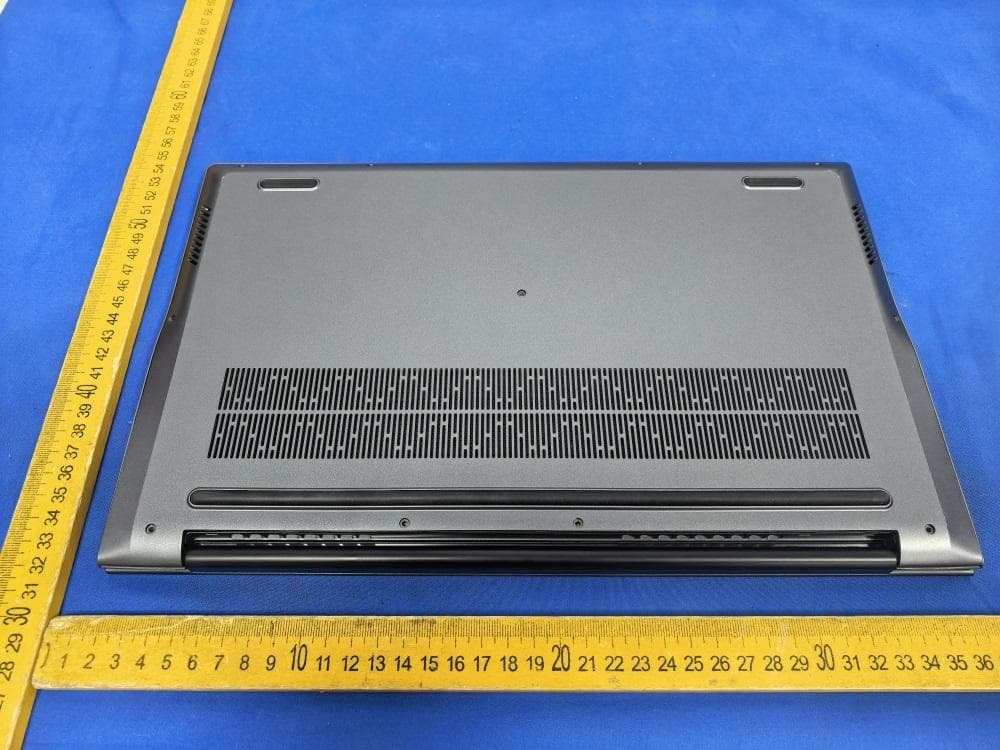
Jul 29, 2026Laptop
Equipment Class
NII - Unlicensed National Information Infrastructure TX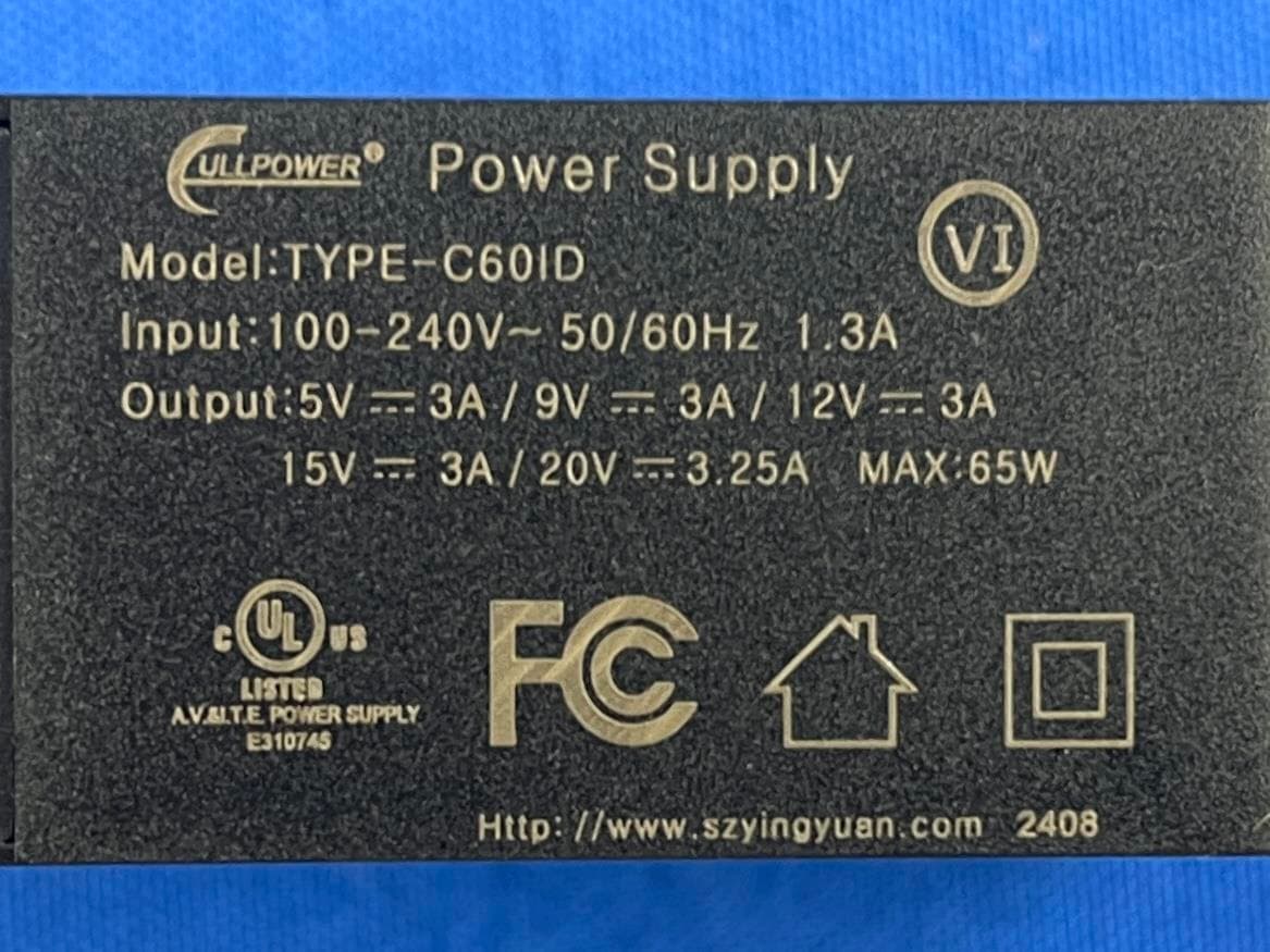
2APUQ-W14198
Sep 05, 2024Personal Computer
Equipment Class
DTS - Digital Transmission System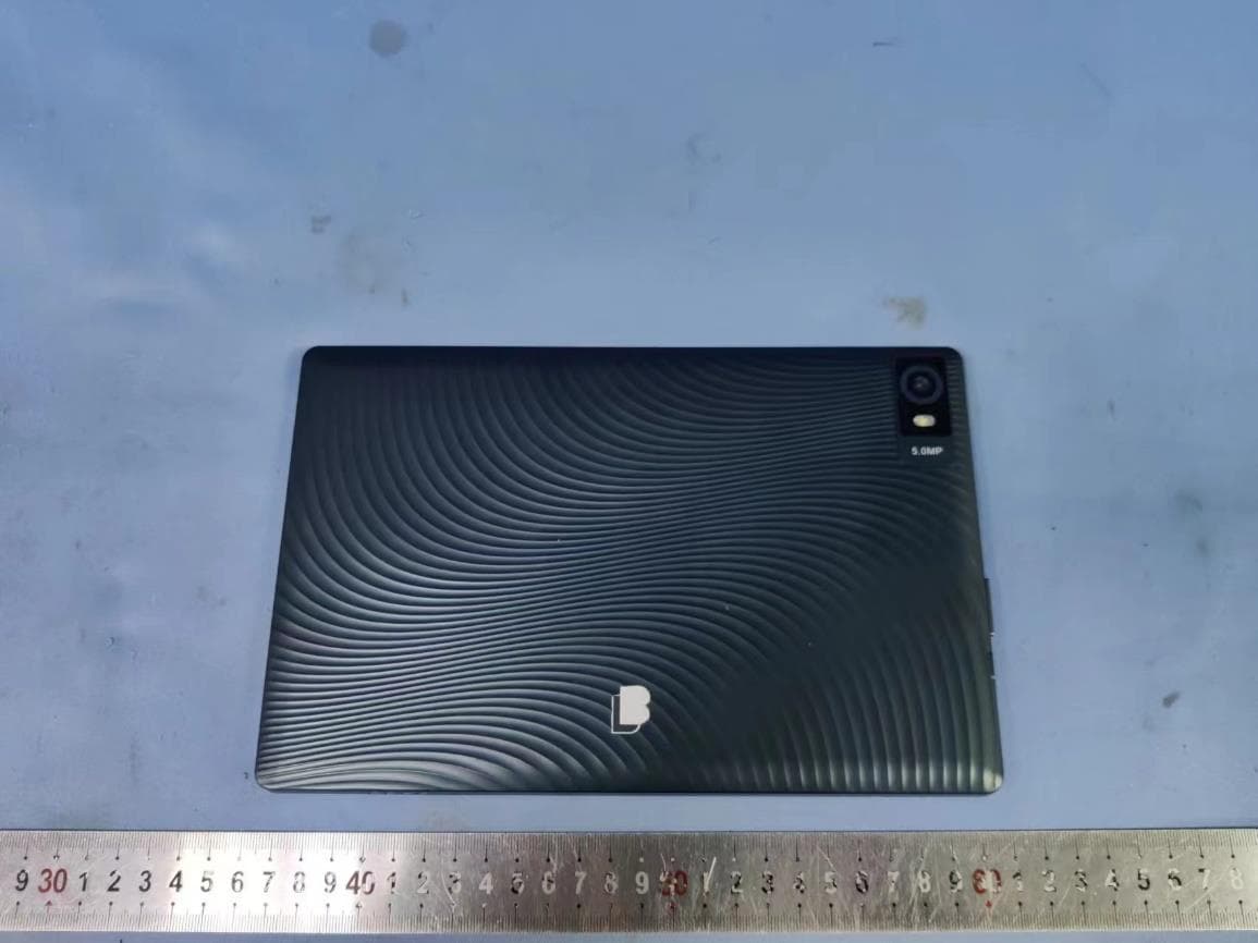
2APUQ-LM1097P
Aug 01, 2024Tablet
Equipment Class
DXX - Part 15 Low Power Communication Device Transmitter2APUQ-T100-001
Jun 12, 2024Smart Projector
Equipment Class
NII - Unlicensed National Information Infrastructure TX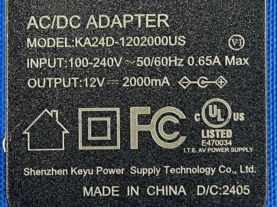
2APUQ-W14118GP
Apr 18, 2024LAPTOP
Equipment Class
DSS - Part 15 Spread Spectrum Transmitter