2APXNLACA116Wireless Charger
ASAP Technology(Jiangxi) Co., Ltd.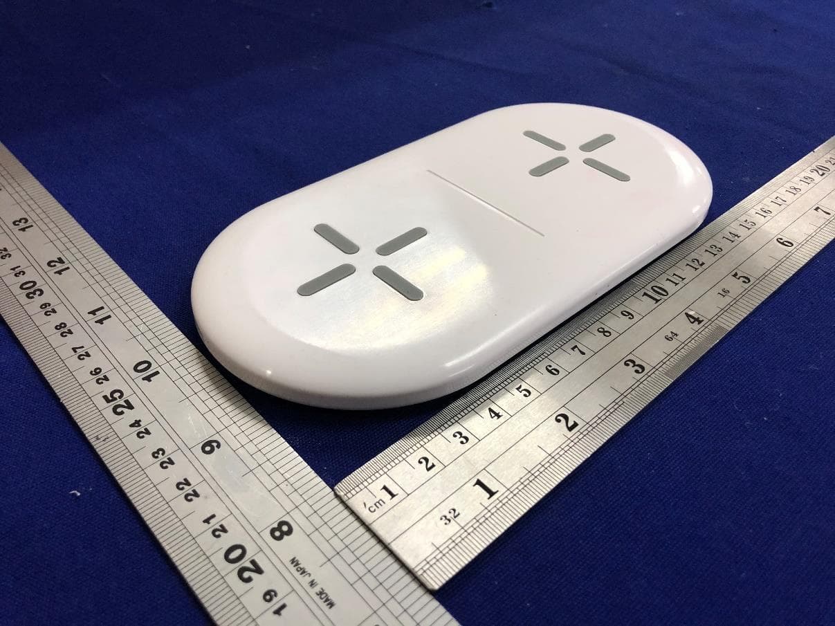
Click to zoom
Application Details
- Equipment Class
- DCD - Part 15 Low Power Transmitter Below 1705 kHz
- Date of Grant
- Feb 25, 2020
- Application Purpose
- Original Equipment
- Date of Application
- Feb 17, 2020
- Equipment Note
- Wireless Charger
- Frequency Range
- 0.11000000 - 0.20500000
- Country
- China
Documents & Files
Document Text
Text extracted from the exhibit documents filed with the FCC. Open a document above to read the original.
Users Manual
comply with the limits for a Class B digital device, **Thick protective case 5mm or a case includes magnet or metallic material, may not allow proper charging function. 99.10 mm 1 3 9 . 6 1 m m Wireless Charging Pad Input Output Dimension WIAWHT100012443 9V/1.67A 5W per coil, total 10W Max 170mm*86mm*11.6mm Compatibility 1.Qi-enabled devices charge up to 5W each side. 2.Any Qi-compatible smartphones or devices. Power Barrel Connecting Port Power Barrel Connecting Power outlet on wall 15W AC adapter How to charge your devices. November 25, 2019_V1 Connect 15W AC Adapter with Charging Pad. Insert power barrel connector to the connecting port of the charging pad. Plug in 15W AC adapter into power outlet for power supply. PRODUCT GUIDE Caution Avoid dropping Do not disassemble No metal objects between devices and wireless charging pad. Thick protective case ≥ 5mm or a case includes magnet or metallic material, may not allow proper charging function. Keep wireless charging pad away from any liquids or moisture The maximum ambient temperature during use of this product must not exceed 45°C. Do not place device in fire or other excessively hot environments. Only use dry cloth or brush to clean this product. Do not use if visible defects are observed on the wireless charging pad. Warning Any changes or modifications not expressly approved by the party responsible for compliance could void the user's authority to operate this equipment. FCC Statements This device complies with Part 15 of the FCC Rules Operation is subject to the following two conditions (1) This device may not cause harmful interference, and (2) This device must accept any interference received including interference that may cause undesired operation NOTE: This equipment has been tested and found to pursuant to Part 15 of the FCC Rules. These limits are designed to provide reasonable protection against harmful interference in a residential installation. This equipment generates uses and can radiate radio frequency energy and, if not installed and used in accordance with the instructions, may cause harmful interference to radio communications. However, there is no guarantee that interference will not occur in a particular installation. If this equipment does cause harmful interference to radio or television reception, which can be determined by turning the equipment o and on, the user is encouraged to try to correct the interference by one or more of the following measures: Reorient or relocate the receiving antenna Increase the separation between the equipment and receiver Connect the equipment into an outlet on a circuit di erent from that to which the receiver is connected Consult the dealer or an experienced radio/TV technician for help This equipment complies with FCC radiation exposure limits set forth for an uncontrolled environment. This equipment should be installed and operated with minimum distance 20cm between the radiator and your body. This transmitter must not be co-located or operating in conjunction with any other antenna or transmitter. November 25, 2019_V1 . Dual 5W Qi Wireless Charging Pad . A 15W AC adapter with 5-ft Cable . User Manual What is in the box? Get to know your Dual 5W Qi Wireless Charging Pad LED status indicator LED Indicator Blue light on for 3 seconds O Blue light on continuously Blue light (flashing) Status Connected to power Stand by for charging Charging device Foreign object detected (Remove it before charging) Begin to charge Place your smartphone(s) or any Qi-enabled device on the center of the charging pad, make sure to cover. LED indicator will be on continuously during charging. Dual 5W Qi Wireless Charging Pad Model: WIAWHT100012443 Need help? We’re here for you every day from 7 a.m. – 9 p.m. CST. Give us a call at 1-888-516-2630 If there is any foreign object detected, LED indicator will be flashing. Remove any foreign object (if any) Example: Magnet or holder *Can charge up to 2 devices at the same time. We ‘d love to hear from you. Scan with your Walmart app and let us know what you think. Connect to Power Supply. LED status indicator Do not place any credit card on the charging device. 681131357715
Cover Letter(s)
ASAP Technology (Jiangxi) Co., Ltd Dec 19th, 2019 Federal Communications Commission 445 12 th Street SW Washington, DC 20554 Subject: Limited Agency Agreement ASAP Technology (Jiangxi) Co., Ltd. FCC ID: 2APXNLACA116 To Whom It May Concern: We, ASAP Technology (Jiangxi) Co., Ltd., hereby authorized Intertek Testing Services to act as our Agent for the purpose of preparing application for FCC ID number 2APXNLACA116 under all applicable parts of the FCC rules and regulations. The effective date of this limited agency agreement is Dec 19th, 2019. The Limited Agency Agreement expires on Dec 19th, 2020, unless sooner terminated or extended by written notice to Intertek Testing Services and the Federal Communications Commission. This is to advise that we are in full compliance with the Anti-Drug Abuse Act. The applicant is not subject to a denial of federal benefits pursuant to Section 5301 of the Anti-Drug Act of 1988, 21 U.S.C. 862, and no party to the application is subject to a denial of federal benefits pursuant to that section. If you have any questions or comments, please do not hesitate to contact me. Sincerely, Xiaolan Deng Manager
Cover Letter(s)
1(2) ASAP Technology (Jiangxi) Co., Ltd. Attention: Certification reviewer RE: Request for Confidentiality FCC ID: 2APXNLACA116 To Whom It May Concern: Permanent Confidentiality [Complete this section if permanent confidentiality is requested] Request to withhold permanently from public review certain portions of the application for equipment certification for the referenced FCC identifiers. This request for confidentiality is made pursuant to 47 CFR 0.457(d) and 0.459 of the FCC Rules. In particular, the following sections of the application are to be kept permanently confidential: [Select one or more of items below, as appropriate] Schematics Block Diagrams Operational Description Tune-up Procedure Parts List Internal Photos (see note) Users Manual (see note) Note 1: Internal Photos may be held confidential 1) if the circuit board or internal components are not accessible to users. For example, it is acceptable if the circuit board is enclosed in epoxy. 2) Also, it is acceptable if the device is not accessible to the public, for example, a device mounted on the top of a large tower (or in a fenced enclosure) such that it is only serviceable by professional designated technicians under a Non-Disclosure Agreement (NDA). All sales for these devices must be under a NDA restricting the disclosure of the propriety information, including internal photos. Users Manual may be held confidential only when the manual contains proprietary technical information intended for professional technicians obligated under a NDA. All sales and distribution of the user’s manual must be under a NDA that restricts the disclosure of the information. In the application cover letter requesting permanent confidentiality the following additional description and the NDA exhibit is required: 1. Describe in detail how internal photos and/or users manual information are controlled to prevent them from becoming public or disclosed to unauthorized persons. 2. Describe how public access is restricted for products serviceable by professional designated technicians. 3. A statement that all sales of the non-consumer device will be under a NDA to include third party sales and that the final user of the device is subject to the NDA. 4. Provide an example of the NDA between the grantee and a purchaser. The request for confidentiality must Note 2: For scanning receiver, the schematics, block diagrams, operational description, tune-up procedure, parts list and internal photos are always held permanently confidential. Short-term Confidentiality [Complete this section if short-term confidentiality is requested] Request to withhold from public review for a period of [please enter 1 to 180] days from the date of the Grant of Equipment Authorization and prior to marketing, certain portions of the application for equipment certification for the referenced FCC identifiers. This request for confidentiality is made pursuant to 47 CFR 0.457(d) and 0.459 of the FCC Rules. In particular, the following sections of the application are to be kept short-term confidential for a period above from the date of the grant [Select one or more of items below that are not selected in the list above, as appropriate] Schematics Block diagrams Operational Description Tune-up Procedure 2(2) Parts List Test Setup Photos External Photos Internal Photos Users Manual Rationale for request for confidentiality: We have invested considerable time and materials in research and development to produce the referenced product. Permanent confidentiality: Disclosure of the permanently confidential portions of this application to competitors would not only give them significant competitive advantages in developing similar products, but would also disclose successful implementation of unpublished, leading edge technology developed by us. Short-term confidentiality: Disclosure of the short-term confidential portions of this application during the period of importation and/or distribution would reveal key aspects of proprietary technology to competitors and diminish the value of our investment in research and development. If you have questions or need further information, please contact the undersigned. Sincerely, Xiaolan Deng Manager Dec 19th, 2019
ID Label/Location Info
7 6 4 3 2 1 .XXX± 0.100.XX± 0.20.X± 0.3X.± 1 .XX°±0.3.X°±0.5.XXX°±0.1X.°±1 PART NO. DWG NO: TITLE: SHEET SCALE 1:2 1/5 REV. A Customer P/N:WIAWHT100012443 L3TWC240-CS-R1 OF LUXSHARE-ICT THESE DRAWINGS AND SPECIFICATIONS WITHOUT THE PRIOR WRITTEN CONSENTAND SHALL NOT BE REPRODUCED,COPIED OR CUED IN ANY MANNER UNITS: mm Customer REV.: * ARE THE PROPERTY OF LUXSHARE-ICT DATE 169.95±0.3 85.95±0.3 11.6±0.2( 含防滑垫与脚垫 ) 11±0.15 Ø 4 ± 0 . 0 5 上下盖间隙 MAX0.25 6 5 上下盖高低级 MAX0.25 DC 孔 LED 孔 Model NO: WIAWHT100012443 Input: 9V 1.67A Output: Each 5W Max.FCC ID: 2APXNLACA116 This device complies with part 15 of the FCC Rules. Operation is subject to the following two conditions:(1) this device may not cause harmful interference,and(2) this device must accept any interference received,including interference that may cause undesired operation. 19XXB 50.5mm 22.6mm14.15 1 2 3 4 2.0-2.5 线圈面至手机支撑面 7
RF Exposure Info
ASAP Technology (Jiangxi) Co., Ltd. TEST REPORT SCOPE OF WORK SAR Assessment– LACA116, WIAWHT100012443 REPORT NUMBER 191204035SZN-002 ISSUE DATE [REVISED DATE] 18 February 2020 [--------------------] PAGES 12 DOCUMENT CONTROL NUMBER RF Exposure © 2017 INTERTEK TEST REPORT Intertek No.: 191204035SZN-002 This report is for the exclusive use of Intertek's Client and is provided pursuant to the agreement between Intertek and its Client. Intertek's responsibility and liability are limited to the terms and conditions of the agreement. Intertek assumes no liability to any party, other than to the Client in accordance with the agreement, for any loss, expense or damage occasioned by the use of this report. Only the Client is authorized to permit copying or distribution of this report and then only in its entirety. Any use of the Intertek name or one of its marks for the sale or advertisement of the tested material, product or service must first be approved in writing by Intertek. The observations and test results in this report are relevant only to the sample tested. This report by itself does not imply that the material, product, or service is or has ever been under an Intertek certification program. Intertek Testing Services Shenzhen Ltd. Longhua Branch 101, 201, Building B, No. 308 Wuhe Avenue, Zhangkengjing Community, GuanHu Subdistrict, LongHua District, ShenZhen. Tel: (86 755) 8601 6288 Fax: (86 755) 8601 6751 Version: 01-November-2017 Page 1 of 12 RF Exposure 101, 201, Building B, No. 308 Wuhe Avenue, Zhangkengjing Community, GuanHu Subdistrict, LongHua District, ShenZhen. Tel: (86 755) 8601 6288 Fax: (86 755) 8601 6751 www.intertek.com Test Report Applicant : ASAP Technology (Jiangxi) Co., Ltd. Ji'an Industrial Park Ji'an Jiangxi China Sample Description Product : Wireless Charger Model No. : LACA116, WIAWHT100012443 Brand Name : onn. Electrical Rating : Input: DC9V 1.67A; Output: Each 5W Max. (Total: 10W Max.) Date Received : 4 December 2019 Date Test Conducted : 4 December 2019 to 10 February 2020 Test Requested : Test for compliance with CFR 47 part 1 Test Method : Environmental evaluation and exposure limit according to FCC CFR 47 part 1, 1.1307(c) and (d), 1.1310 Test Result : Pass Conclusion : When determining of test conclusion, measurement uncertainty of tests have been considered. ******************************** End of Page ******************************** Prepared and Checked By: Approved By: Jeff Liang Kidd Yang Engineer Technical Supervisor Date: 18 February 2020 TEST REPORT Intertek No.: 191204035SZN-002 Version: 01-November-2017 Page 2 of 12 RF Exposure Test Report Test Setup Configuration Note - The RF exposure test is performed in the shield room. - The test distance is between the edge of the charger and the geometric centre of probe. - The model: WIAWHT100012443 is the same as the model LACA116 in hardware and electrical aspect. Test Equipment List Name of instrument Model Manufacturer Cal. Date Due Date Electric and Magnetic Field Analyzer EHP-50F Narda 2019-06-27 2020-06-27 TEST REPORT Intertek No.: 191204035SZN-002 Version: 01-November-2017 Page 3 of 12 RF Exposure Reference Limit: Environmental evaluation and exposure limit according to FCC CFR 47 part 1, 1.1307(c) and (d), 1.1310 According to FCC 1.1310: The criteria listed in the following table shall be used to evaluate the environment impact of human exposure to radio frequency (RF) radiation. LIMITS FOR MAXIMUM PERMISSIBLE EXPOSURE (MPE) Frequency Range ( MHz ) Electric Field strength (V/m) Magnetic Field Strength (A/m) Power Density (mW/cm 2 ) Average Time (minutes) (A) Limits for Occupational/Controlled Exposure 0.3 – 3.0 614 1.63 (100) * 6 (B) Limits for General Population/Uncontrolled Exposure 0.3 – 1.34 614 1.63 (100) * 30 Note: * = Plane wave equivalent power density Test Result (Both sides are charging and Stand-by): H-Field Strength at 15 cm surrounding the EUT and 20cm above the top surface of the EUT Frequency Range (MHz) EUT Operation mode Probe Position Front (A/m) Probe Position Rear (A/m) Probe Position Left (A/m) Probe Position Right (A/m) Probe Position Top (A/m) Limits (A/m) 0.110- 0.205 1% Battery Level 0.0582 0.0498 0.0326 0.1196 0.0409 1.63 0.110- 0.205 50% Battery Level 0.0575 0.0488 0.0321 0.1188 0.0405 1.63 0.110- 0.205 99% Battery Level 0.0571 0.0495 0.0313 0.1190 0.0401 1.63 0.110- 0.205 Stand-by 0.0025 0.0023 0.0025 0.0024 0.0024 1.63 E-Field Strength at 15 cm surrounding the EUT and 20cm above the top surface of the EUT Frequency Range (MHz) EUT Operation mode Probe Position Front (V/m) Probe Position Rear (V/m) Probe Position Left (V/m) Probe Position Right (V/m) Probe Position Top (V/m) Limits (V/m) 0.110- 0.205 1% Battery Level 1.0853 0.7306 0.9632 0.9937 1.0136 614 0.110- 0.205 50% Battery Level 1.0844 0.7298 0.9628 0.9931 1.0131 614 0.110- 0.205 99% Battery Level 1.0845 0.7301 0.9626 0.9925 0.0132 614 0.110- 0.205 Stand-by 0.0674 0.0682 0.0701 0.0691 0.0678 614 TEST REPORT Intertek No.: 191204035SZN-002 Version: 01-November-2017 Page 4 of 12 RF Exposure Test Result (Only the left side is charging): H-Field Strength at 15 cm surrounding the EUT and 20cm above the top surface of the EUT Frequency Range (MHz) EUT Operation mode Probe Position Front (A/m) Probe Position Rear (A/m) Probe Position Left (A/m) Probe Position Right (A/m) Probe Position Top (A/m) Limits (A/m) 0.110- 0.205 1% Battery Level 0.0571 0.0705 0.0684 0.0533 0.0568 1.63 0.110- 0.205 50% Battery Level 0.0567 0.0702 0.0683 0.0532 0.0565 1.63 0.110- 0.205 99% Battery Level 0.0569 0.0698 0.0683 0.0529 0.0567 1.63 E-Field Strength at 15 cm surrounding the EUT and 20cm above the top surface of the EUT Frequency Range (MHz) EUT Operation mode Probe Position Front (V/m) Probe Position Rear (V/m) Probe Position Left (V/m) Probe Position Right (V/m) Probe Position Top (V/m) Limits (V/m) 0.110- 0.205 1% Battery Level 0.4027 0.4096 0.3832 0.4449 0.3884 614 0.110- 0.205 50% Battery Level 0.4003 0.4089 0.3832 0.4442 0.3880 614 …
Text truncated - open the document above for the full version.
Test Report
ASAP Technology (Jiangxi) Co., Ltd. TEST REPORT SCOPE OF WORK FCC TESTING–LACA116, WIAWHT100012443 REPORT NUMBER 191204035SZN-001 ISSUE DATE [REVISED DATE] 18 February 2020 [--------------------] PAGES 20 DOCUMENT CONTROL NUMBER FCC ID 209_b © 2017 INTERTEK Test Report This report is for the exclusive use of Intertek's Client and is provided pursuant to the agreement between Intertek and its Client. Intertek's responsibility and liability are limited to the terms and conditions of the agreement. Intertek assumes no liability to any party, other than to the Client in accordance with the agreement, for any loss, expense or damage occasioned by the use of this report. Only the Client is authorized to permit copying or distribution of this report and then only in its entirety. Any use of the Intertek name or one of its marks for the sale or advertisement of the tested material, product or service must first be approved in writing by Intertek. The observations and test results in this report are relevant only to the sample tested. This report by itself does not imply that the material, product, or service is or has ever been under an Intertek certification program. Intertek Testing Services Shenzhen Ltd. Longhua Branch 101, 201, Building B, No. 308 Wuhe Avenue, Zhangkengjing Community, GuanHu Subdistrict, LongHua District, ShenZhen. Tel: (86 755) 8601 6288 Fax: (86 755) 8601 6751 Version: 01-November-2017 Page: 1 of 20 FCC ID 209_b 101, 201, Building B, No. 308 Wuhe Avenue, Zhangkengjing Community, GuanHu Subdistrict, LongHua District, ShenZhen. Tel: (86 755) 8601 6288 Fax: (86 755) 8601 6751 www.intertek.com ASAP Technology (Jiangxi) Co., Ltd. Application For Certification FCC ID: 2APXNLACA116 Wireless Charger Model: LACA116, WIAWHT100012443 Transmitter Report No.: 191204035SZN-001 We hereby certify that the sample of the above item is considered to comply with the requirements of FCC Part 15, Subpart C for Intentional Radiator, mention 47 CFR [10-1-18] Prepared and Checked by: Approved by: Jeff Liang Kidd Yang Engineer Technical Supervisor Date: 18 February 2020 Test Report Intertek Report No.: 191204035SZN-001 Version: 01-November-2017 Page: 2 of 20 FCC ID 209_b MEASUREMENT/TECHNICAL REPORT This report concerns (check one) Original Grant X Class II Change Equipment Type: DCD - Part 15 Low Power Transmitter Below 1705 kHz Deferred grant requested per 47 CFR 0.457(d)(1)(ii)? Yes No X If yes, defer until: date Company Name agrees to notify the Commission by: date of the intended date of announcement of the product so that the grant can be issued on that date. Transition Rules Request per 15.37? Yes No X If no, assumed Part 15, Subpart C for intentional radiator - the new 47 CFR [10-01-18] Edition] provision. Report prepared by: Jeff Liang Intertek Testing Services Shenzhen Ltd. Longhua Branch 101, 201, Building B, No. 308 Wuhe Avenue, Zhangkengjing Community, GuanHu Subdistrict, LongHua District, ShenZhen. Tel: (86 755) 8614 0743 Fax: (86 755) 8601 6751 Test Report Intertek Report No.: 191204035SZN-001 Version: 01-November-2017 Page: 3 of 20 FCC ID 209_b Table of Contents 1.0 Summary of Test Results ..................................................................................... 4 2.0 General Description .............................................................................................. 5 2.1 Product Description .............................................................................................. 5 2.2 Related Submittal(s) Grants ................................................................................. 5 2.3 Test Methodology ................................................................................................ 5 2.4 Test Facility ......................................................................................................... 5 3.0 System Test Configuration ................................................................................... 6 3.1 Justification ......................................................................................................... 6 3.2 EUT Exercising Software ..................................................................................... 6 3.3 Special Accessories ............................................................................................. 6 3.4 Equipment Modification ........................................................................................ 7 3.5 Measurement Uncertainty .................................................................................... 7 3.6 Support Equipment List and Description ............................................................. 7 4.0 Measurement Results ........................................................................................... 8 4.1 Field Strength Calculation .................................................................................... 8 4.2 Radiated Emission Configuration Photograph .................................................... 9 4.3 Radiated Spurious Emission ................................................................................ 9 4.4 Conducted Emission Configuration Photograph ................................................. 12 4.5 Conducted Emission.......................................................................................... 12 5.0 Equipment Photographs .................................................................................... 15 6.0 Product Labelling ................................................................................................ 15 7.0 Technical Specifications .................................................................................... 15 8.0 Instruction Manual .............................................................................................. 15 9.0 Miscellaneous Information ................................................................................. 16 9.1 20dB Bandwidth .............................................................…
Text truncated - open the document above for the full version.
Contact Information
Applicant
Xiaolan Deng
Technical Contact
Intertek Testing Services Shenzhen Ltd. Longhua BrWilliam Chen
[email protected](86 755) 8601 6288
101, 201, Block B, No. 308 Wuhe Blvd, Zhangkengjin · Shenzhen · China
Non-Technical Contact
Intertek Testing Services Shenzhen Ltd. Longhua BrWilliam Chen
[email protected](86 755) 8601 6288
Test Firm
Intertek Testing Services Shenzhen Ltd. Longhua BrHolly Ou
[email protected]+86 755 86140691
Technical Specifications
| # | Rule Parts | Frequency Range | Power Output |
|---|---|---|---|
| 1 | 15C | 0.11 MHz - 0.205 MHz | - |
Other Applications from ASAP Technology(Jiangxi) Co., Ltd.
2APXN-WL2506
Jan 06, 2026Wireless Charger Module
Equipment Class
DCD - Part 15 Low Power Transmitter Below 1705 kHz2APXNLACC135
Jul 03, 2024Wireless charger
Equipment Class
DCD - Part 15 Low Power Transmitter Below 1705 kHz2APXNLACC137
Jul 03, 2024Wireless charger
Equipment Class
DCD - Part 15 Low Power Transmitter Below 1705 kHz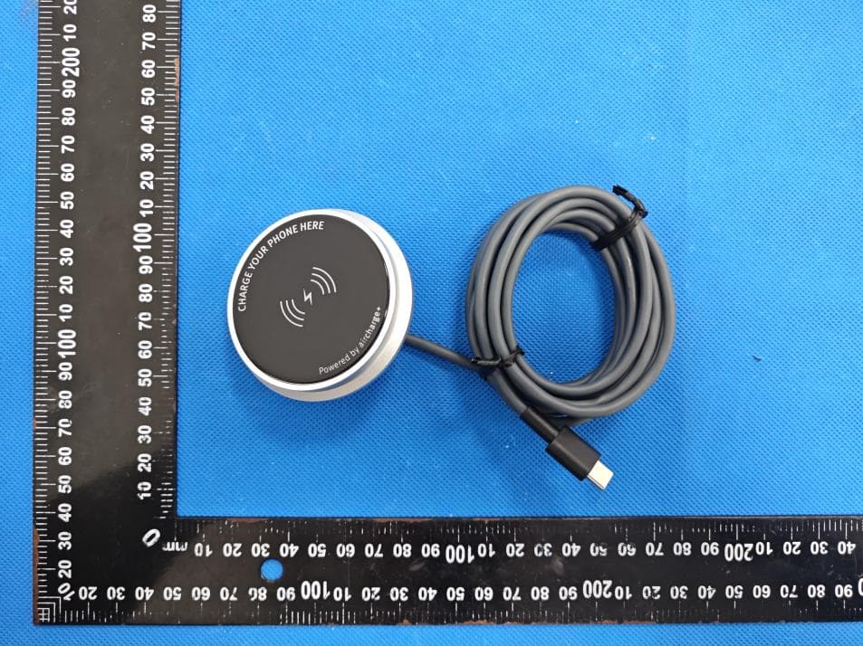
2APXN-LACC119
Aug 19, 2023Aircharge Mag
Equipment Class
DCD - Part 15 Low Power Transmitter Below 1705 kHz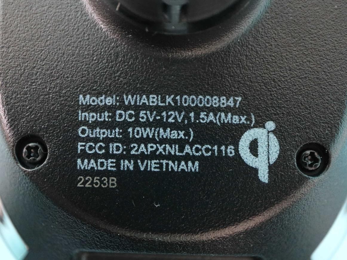
2APXNLACC1161
Apr 13, 202310W Qi Wireless Car Charger
Equipment Class
DCD - Part 15 Low Power Transmitter Below 1705 kHz