2AQ8A-KP1D7Kapture Auto Deadbolt
Pamex Inc.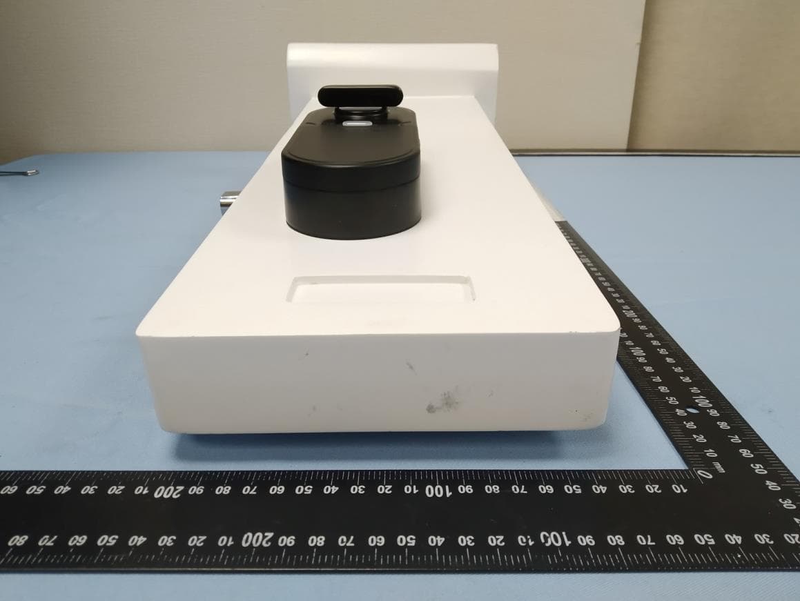
Click to zoom
Application Details
- Equipment Class
- DTS - Digital Transmission System
- Date of Grant
- Aug 16, 2020
- Application Purpose
- Original Equipment
- Date of Application
- Jul 22, 2020
- Equipment Note
- Kapture Auto Deadbolt
- Frequency Range
- 2402.00000000 - 2480.00000000
- Company
- Pamex Inc.
- Country
- United States
Documents & Files
Document Text
Text extracted from the exhibit documents filed with the FCC. Open a document above to read the original.
Users Manual
Product Introduction & User Instructions Kapture KP1-D7 (KP1-D791, KP1-D7P1) Smart Home Lock With Mechanical Key Kapture KP1-LINK (Optional) 05/2020 Agenda Product Features1 Operation Modes1 Common Functions2 Keypad Programming Mode3 Stand-Alone Mode3 Link Mode4 Detailed Function Description4 First time to power up4 Battery change4 Access the lock via the keypad code5 Lock/Unlock UI5 Privacy Mode5 Low Battery Level6 Keypad Programming Commands6 Reset the lock7 Key Cover Open7 Lock Out8 Volume Control8 Auto-Lock8 Lock Error8 Kapture Cloud Account Registration (Sign Up)9 Log in the Kapture App9 Paring the app to the lock via the Bluetooth (Adding A Lock)9 Lock Settings in Kapture App10 User Roles10 Access the lock through the app11 Permissions11 Audit Trail12 Report Problem13 Lock Firmware Update14 Install/Remove LINK14 Real-time notification14 Upgrade LINK Firmware15 FCC Statement16 NCC Statement16 Product Features Included In The Box (Smart Lock) ●A Smart Lock ●4 AA Batteries ●A Deadbolt ●Mounting Hardware ●Installation Guide (Hardware) ●User Manual Available Colors ●Matt Black ●Satin Nickel Included In The Box (Link) ●A wifi bridge adapter ●Installation Guide Operation Modes The Kapture lock can function on one of the three modes mentioned below. ●Keypad Programming Mode ○In this mode, a smartphone is needless when operating a Kapture lock. After the hardware installation, setting the lock and adding the user’s keypad code via the keypad. ●Stand-Alone Mode (Bluetooth Only) ○In this mode, you need to download a Kapture app and register an account. You can operate the lock after a successful pairing to the lock via the Bluetooth. ○Kapture locks can be paired under an account. ●Link Mode (Bluetooth + Wifi Bridge) 1 ○Under Stand-Alone mode, and if connecting the Kapture lock to a Kapture Link, the lock will be capable of providing the remote control management. Not only the real-time events can pop-up on the Kapture app but also an alert notification will receive immediately on the app. Both master and family can remotely access the lock. ○Voice assistant: You can access a registered lock through Amazon Alexa or Google Assistant. Common Functions ➔Users can access the lock via the physical kay or keypad. ➔An initial access code, which is the master code, is 147369. Master code is a changeable six-digit code, we suggest that it is for master use only. ➔Kapture lock can store user keypad codes up to a hundred sets. ➔Access the door via the turnpiece if you stay indoors. ➔When the lock is on Privacy Mode, only the physical key or the Mater’s Kapture app can unlock the door from the outdoors. ➔Press icon once to straightly lock the door from the exterior keypad. ➔The key cover locates the exterior lock and hides the cylinder. If it stays open within a period of time, the alert will activate. And master’s Kapture app will receive the alert under Link Mode. ➔There is an LED on the exterior lock that tells all the access UI whether success or failure. ➔Both exterior and the interior lock have a buzzer that tells all the access UI whether success or failure. ➔The lock is power-saving and normally remains to hibernate. In normal use, over a year’s lifetime with four AA batteries. ➔Under hibernated, the exterior panel will auto-shine and ready for operating when touching by hand. ➔The lock will auto-lock when the battery change. The tesla coil is useless. ➔The latch recognition will do when powering on the lock for the very first time. ➔The length of the user keypad code can be 4-8 digits. ➔To press the reset button in the interior returns the lock to factory default. ➔A low battery LED in the interior will continuously shine to notify users to change the batteries. ➔Three stages of keypad lockout, preventing from the bad intention. ➔Four stages of volume control, from sound to silence. ➔Adjustable time period auto-lock function. ➔Lock errors auto-recognition, preventing from the system error. 2 Keypad Programming Mode Requires: None Key Features : ➔Keypad Programming Mode is the default operating mode. ➔This mode allows users to use the keypad, setting the lock with a Master code. (See Keypad Programming Commands). Stand-Alone Mode Requires : ●A Smart Phone With Bluetooth Capability (iOS, Android Supported) and internet access. ●Install the Kapture app and register a Kapture Cloud account. Key Features : ➔Equipped with Bluetooth 5.0 communication technology standards, transmit the data via AES encryption, guard against the malicious attacks from hackers. ➔Encrypted-communication between smartphone and Kapture Cloud goes through SSL, guard against the malicious attacks from hackers. ➔Log in the Kapture Cloud is needed when using the below functions. ➔There are three different user roles in the lock, including Owner, Family, and Guest. Each role has its own user rights. ➔Before operating the lock setting, you have to pair the lock with the Kapture app via Bluetooth in advance. ➔Users can access the door via physical key, keypad code, or the Kapture app. ➔The owner can manage the user right through the app and manage it anywhere you want for real-time control. ➔Up to 100 Family or Guests can be invited through Owner or Family via the app to access the lock. ➔Users (Owner, Family, Guest) can set their own keypad code via the app. Guest’s keypad code is unique. ➔There are three types of Guest’s permissions:1. Always (unlimited in a given period) 2. Weekly re-occurring 3.Single access pass. ➔The Kapture app can tell all the events to the lock, including access to the lock, user right change, and system status change. Also, you may check with the user, the date and the way on the history if access via the app or keypad code. ➔Directly use the app to do the lock OTA through the Kapture cloud. ➔The low battery alert will notify the user’s app when the smartphone is close enough. ➔When using the Report Problem on the Kapture App, Pamex will respond as soon as we can to provide you better s…
Text truncated - open the document above for the full version.
Cover Letter(s)
Theory of Operation/Technical Description – FCC ID: 2AQ8A-KP1D7 Product name: Model name: KP1-D7P1/ KP1-D791 - RF circuit function: The product are based on the CC2652R modules The major part of this IC is a BLE and Zigbee mode compliant transceiver. The Zigbee function of this product will be turned off using software. Will not be used by the final consumer. - Description of all modulation schemes used in the product:
Cover Letter(s)
17-Jul-20 Federal Communications Commission 7435 Oakland Mills Road Columbia, MD 21046 FCC ID: 2AQ8A-KP1D7 Models: KP1-D7P1/ KP1-D791 Declaration on Similarity We herewith confirm that for the models listed above the RF Transmitter Module is Electrically Identical. The differences are in the model numbers and in the digital data interface. ___________________ Charles Chen (Signature) (Printed)
External Photos
Appendix P Photo Documentation Page 1 of 16 60376684 001 Product: Kapture Auto Deadbolt Brand name: Kapture Type Identification: KP1-D7P1, KPI-D791 KP1-D7P1 Appendix P Photo Documentation Page 2 of 16 60376684 001 Product: Kapture Auto Deadbolt Brand name: Kapture Type Identification: KP1-D7P1, KPI-D791 Appendix P Photo Documentation Page 3 of 16 60376684 001 Product: Kapture Auto Deadbolt Brand name: Kapture Type Identification: KP1-D7P1, KPI-D791 Appendix P Photo Documentation Page 4 of 16 60376684 001 Product: Kapture Auto Deadbolt Brand name: Kapture Type Identification: KP1-D7P1, KPI-D791 KP1-D791 Appendix P Photo Documentation Page 5 of 16 60376684 001 Product: Kapture Auto Deadbolt Brand name: Kapture Type Identification: KP1-D7P1, KPI-D791 Appendix P Photo Documentation Page 6 of 16 60376684 001 Product: Kapture Auto Deadbolt Brand name: Kapture Type Identification: KP1-D7P1, KPI-D791 Appendix P Photo Documentation Page 7 of 16 60376684 001 Product: Kapture Auto Deadbolt Brand name: Kapture Type Identification: KP1-D7P1, KPI-D791
ID Label/Location Info
Lable Artwork KP1-D791(Matt Black) KP1-D7P1(Satin Nickel)
Internal Photos
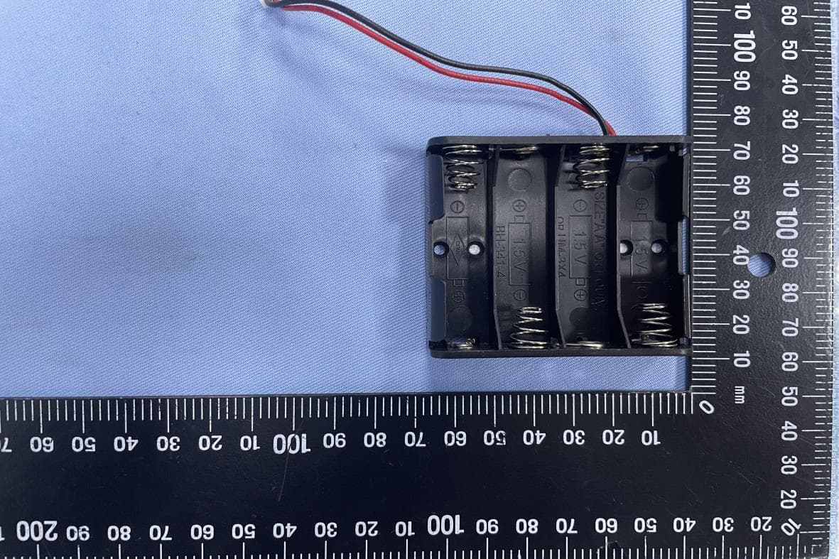
Appendix P Photo Documentation Page 8 of 16 60376684 001 Product: Kapture Auto Deadbolt Brand name: Kapture Type Identification: KP1-D7P1, KPI-D791 Appendix P Photo Documentation Page 9 of 16 60376684 001 Product: Kapture Auto Deadbolt Brand name: Kapture Type Identification: KP1-D7P1, KPI-D791 Appendix P Photo Documentation Page 10 of 16 60376684 001 Product: Kapture Auto Deadbolt Brand name: Kapture Type Identification: KP1-D7P1, KPI-D791 Appendix P Photo Documentation Page 11 of 16 60376684 001 Product: Kapture Auto Deadbolt Brand name: Kapture Type Identification: KP1-D7P1, KPI-D791 Appendix P Photo Documentation Page 12 of 16 60376684 001 Product: Kapture Auto Deadbolt Brand name: Kapture Type Identification: KP1-D7P1, KPI-D791 Appendix P Photo Documentation Page 13 of 16 60376684 001 Product: Kapture Auto Deadbolt Brand name: Kapture Type Identification: KP1-D7P1, KPI-D791 Appendix P Photo Documentation Page 14 of 16 60376684 001 Product: Kapture Auto Deadbolt Brand name: Kapture Type Identification: KP1-D7P1, KPI-D791 Antenna Appendix P Photo Documentation Page 15 of 16 60376684 001 Product: Kapture Auto Deadbolt Brand name: Kapture Type Identification: KP1-D7P1, KPI-D791 Appendix P Photo Documentation Page 16 of 16 60376684 001 Product: Kapture Auto Deadbolt Brand name: Kapture Type Identification: KP1-D7P1, KPI-D791
RF Exposure Info
Produkte Products Prü fbericht - Nr.: Test Report No. 60376684 001 Seite 36 von 40 Page 36 of 40 6. Safety Human exposure 6.1 Radio Frequency Exposure Compliance 6.1.1 Electromagnetic Fields RESULT: Passed Test standard : FCC KDB Publication 447498 D01 v06 FCC CFR 47 Part 2 Subpart J Section 2.1091 Separation distance is more than 20 cm, thus mobile device exposure limits can be applied. FCC Maximum Exposure: Mode Frequenc y (MHz) Antenna Gain (dBi) Antenna Gain (numeric) Maximum Output Power (dBm) Output Power (mW) Power Density (S)(mW/cm 2 ) Test Result GFSK 2M 2402 3.3 2.138 5.50 3.5481 0.00151 Pass Limit FCC: 1500-100,000 MHz 1.0 mW/cm 2
Test Report
Test Report No.60376684 001 Appendix D: Radiated and Mains Spurious Emission Data (File: 60376684 001Appendix D) Contents Spurious Emissions, Bandedge for BLE 1M .................................................................................................. 2 Spurious Emissions, Bandedge for BLE 2M ................................................................................................ 14 Spurious Emissions, TX Mode, 9kHz-30MHz for BLE 2M ........................................................................ 26 Spurious Emissions, TX Mode, 30MHz-1GHz for BLE 2M ....................................................................... 28 Spurious Emissions, TX Mode, 1GHz-26.5GHz for BLE 1M ..................................................................... 30 Spurious Emissions, TX Mode, 1GHz-26.5GHz for BLE 2M ..................................................................... 36 2 Spurious Emissions, Bandedge for BLE 1M 2402MHz 3 4 5 6 2440MHz 7 8 9 10 2480MHz 11 12 13 14 Spurious Emissions, Bandedge for BLE 2M 2402MHz 15 16 17 18 2440MHz 19 20 21 22 2480MHz 23 24 25 26 Spurious Emissions, TX Mode, 9kHz-30MHz for BLE 2M 2480MHz 27 28 Spurious Emissions, TX Mode, 30MHz-1GHz for BLE 2M 2480MHz 29 30 Spurious Emissions, TX Mode, 1GHz-26.5GHz for BLE 1M 2402MHz 31 32 2440MHz 33 34 2480MHz 35 36 Spurious Emissions, TX Mode, 1GHz-26.5GHz for BLE 2M 2402MHz 37 38 2440MHz 39 40 2480MHz 41
Test Report
Prü fbericht - Produkte Test Report - Products Prü fbericht-Nr.: Test report no.: 60376684 001 Auftrags-Nr.: Order no.: 238486682 Seite 1 von 40 Page 1 of 40 Kunden-Referenz-Nr.: Client reference no.: N/A Auftragsdatum: Order date: 2020.05.18 Auftraggeber: Client: PAMEX INC. 4680 VINITA CT, CHINO, CA, 91710, UNITED STATES Prü fgegenstand: Test item: Kapture Auto Deadbolt Bezeichnung / Typ-Nr.: Identification / Type no.: KP1-D791, KP1-D7P1 Auftrags-Inhalt: Order content: FCC Part 15C Test report (BLE) Prü fgrundlage: Test specification: FCC 47CFR Part 15: Subpart C Section 15.247 Wareneingangsdatum: Date of sample receipt: 2020.05.19 Prü fmuster-Nr.: Test sample no: A002831089-001, A002831089-003 Prü fzeitraum: Testing period: 2020.05.21 - 2020.05.28 Ort der Prü fung: Place of testing: EMC/RF Laboratory Taipei Prü flaboratorium: Testing laboratory: Taipei Testing laboratories Prü fergebnis*: Test result*: Pass ü berprü ft von: reviewed by: M a r s Y . J . L i n genehmigt von: authorized by: R y a n W . T . C h e n atum: 2020.06.01 Date: Datum: 2020.06.01 Date: Stellung / Position: Project Engineer Stellung / Position: Project Manager Sonstiges / Other: Color differences: KP1-D791 is the mian model with matt black, and the series model, KP1-D7P1, is satin nickel. Zustand des Prü fgegenstandes bei Anlieferung: Condition of the test item at delivery: Prüfmuster vollständig und unbeschädigt Test item complete and undamaged * Legende: 1 = sehr gut 2 = gut 3 = befriedigend 4 = ausreichend 5 = mangelhaft P(ass) = entspricht o.g. Prüfgrundlage(n) F(ail) = entspricht nicht o.g. Prüfgrundlage(n) N/A = nicht anwendbar N/T = nicht getestet * Legend: 1 = very good 2 = good 3 = satisfactory 4 = sufficient 5 = poor P(ass) = passed a.m. test specification(s) F(ail) = failed a.m. test specification(s) N/A = not applicable N/T = not tested Dieser Prü fbericht bezieht sich nur auf das o.g. Prü fmuster und darf ohne Genehmigung der Prü fstelle nicht auszugsweise vervielfältigt werden. Dieser Bericht berechtigt nicht zur Verwendung eines Prü fzeichens. This test report only relates to the a. m. test sample. Without permission of the test center this test report is not permitted to be duplicated in extracts. This test report does not entitle to carry any test mark. TUV Rheinland Taiwan Ltd. 11F., No. 758, Sec. 4, Bade Rd., Taipei 105, Taiwan, R.O.C. Produkte Products Prü fbericht - Nr.: Test Report No. 60376684 001 Seite 2 von 40 Page 2 of 40 TEST SUMMARY 5.1.1 ANTENNA REQUIREMENT RESULT: Passed 5.1.2 MAXIMUM CONDUCTED PEAK OUTPUT POWER RESULT: Passed 5.1.3 6DB BANDWIDTH AND 99% BANDWIDTH RESULT: Passed 5.1.4 POWER DENSITY RESULT: Passed 5.1.5 CONDUCTED SPURIOUS EMISSIONS AND FREQUENCY BAND EDGE MEASURED IN 100KHZ BANDWIDTH RESULT: Passed 5.1.6 SPURIOUS EMISSION RESULT: Passed 6.1.1 ELECTROMAGNETIC FIELDS RESULT: Passed Produkte Products Prü fbericht - Nr.: Test Report No. 60376684 001 Seite 3 von 40 Page 3 of 40 Contents 1. GENERAL REMARKS ............................................................................................... 5 1.1 COMPLEMENTARY MATERIALS ................................................................................. 5 1.2 DECISION RULE OF CONFORMITY.............................................................................. 5 2. TEST SITES ............................................................................................................ 6 2.1 TEST LABORATORY ................................................................................................ 6 2.2 TEST FACILITY ........................................................................................................ 6 2.3 LIST OF TEST AND MEASUREMENT INSTRUMENTS ...................................................... 7 2.4 TRACEABILITY ........................................................................................................ 8 2.5 CALIBRATION ......................................................................................................... 8 2.6 MEASUREMENT UNCERTAINTY ................................................................................. 8 3. GENERAL PRODUCT INFORMATION ........................................................................... 9 3.1 PRODUCT FUNCTION AND INTENDED USE ................................................................. 9 3.2 SYSTEM DETAILS AND RATINGS ............................................................................... 9 3.3 INDEPENDENT OPERATION MODES ......................................................................... 10 3.4 NOISE GENERATING AND NOISE SUPPRESSING PARTS ............................................ 10 3.5 SUBMITTED DOCUMENTS ....................................................................................... 10 4. TEST SET-UP AND OPERATION MODES ................................................................... 11 4.1 PRINCIPLE OF CONFIGURATION SELECTION ............................................................ 11 4.2 TEST OPERATION AND TEST SOFTWARE................................................................. 11 4.3 SPECIAL ACCESSORIES AND AUXILIARY EQUIPMENT ............................................... 12 4.4 COUNTERMEASURES TO ACHIEVE EMC COMPLIANCE .............................................. 12 4.5 TEST SETUP DIAGRAM .......................................................................................... 13 5. TEST RESULTS ..................................................................................................... 15 5.1 TRANSMITTER REQUIREMENT & TEST SUITES ......................................................... 15 5.1.1 Antenna Requirement ................................................................................................................ 15 5.1.2 Maximum conducted Peak output power ................................................................................... 16 5.1.3 6dB Bandwidth and 99% Bandwidth .................................................................…
Text truncated - open the document above for the full version.
Test Setup Photos
Produkte Products Prü fbericht - Nr.: Test Report No. 60376684 001 Seite 37 von 40 Page 37 of 40 7. Photographs of the Test Set-Up Photograph 1: Set-up for Spurious Emissions (Front View 1) Photograph 2: Set-up for Spurious Emissions (Front View 2) Produkte Products Prü fbericht - Nr.: Test Report No. 60376684 001 Seite 38 von 40 Page 38 of 40 Photograph 3: Set-up for Spurious Emissions (Back View 1) Photograph 4: Set-up for Spurious Emissions (Back View 2) Produkte Products Prü fbericht - Nr.: Test Report No. 60376684 001 Seite 39 von 40 Page 39 of 40 Photograph 5: Set-up for Spurious Emissions (Back View 3) Photograph 6: Set-up for Spurious Emissions (Back View 4)
Contact Information
Applicant
Charles Chen(Product Manager)
Test Firm
TUV Rheinland Taiwan Ltd. Taipei Testing Lab.Kenji Lin
Technical Specifications
| # | Rule Parts | Frequency Range | Power Output |
|---|---|---|---|
| 1 | 15C | 2.40 GHz - 2.48 GHz | 3.55 mW |
Other Applications from Pamex Inc.
2AQ8A-EKSLNP5C
Mar 27, 2023Enkore Smart Leverset
Equipment Class
DXX - Part 15 Low Power Communication Device Transmitter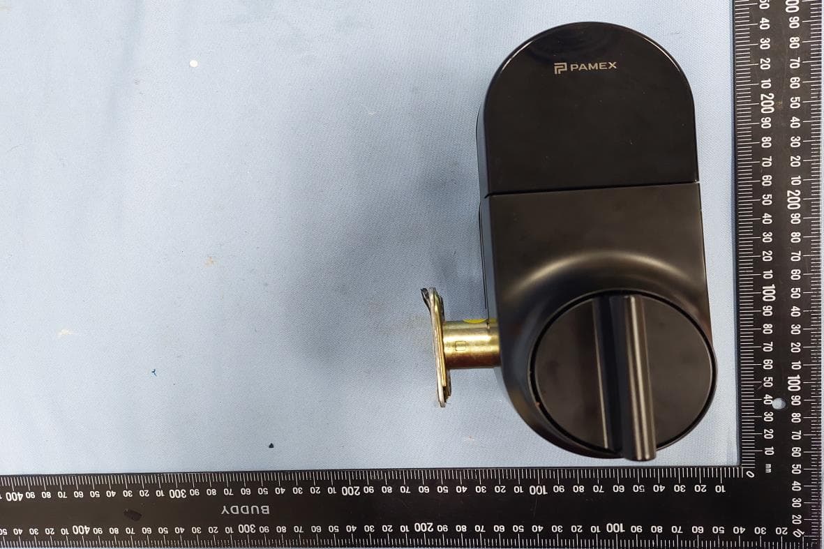
2AQ8A-EKSD7X1S
Feb 19, 2023Enkore Smart Semi-Auto Electronic Deadbolt
Equipment Class
DTS - Digital Transmission System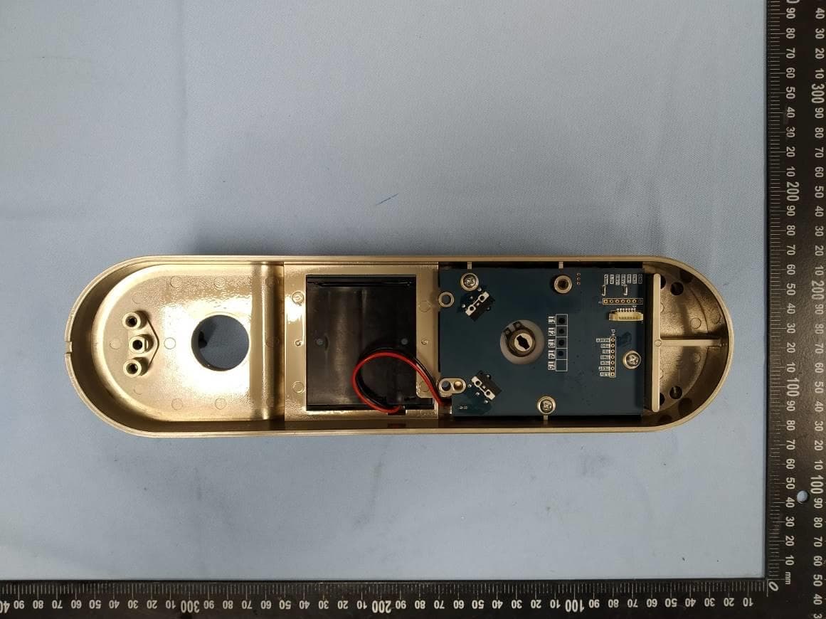
2AQ8A-KE1-DNI-A
Aug 30, 2020Enkore
Equipment Class
DTS - Digital Transmission System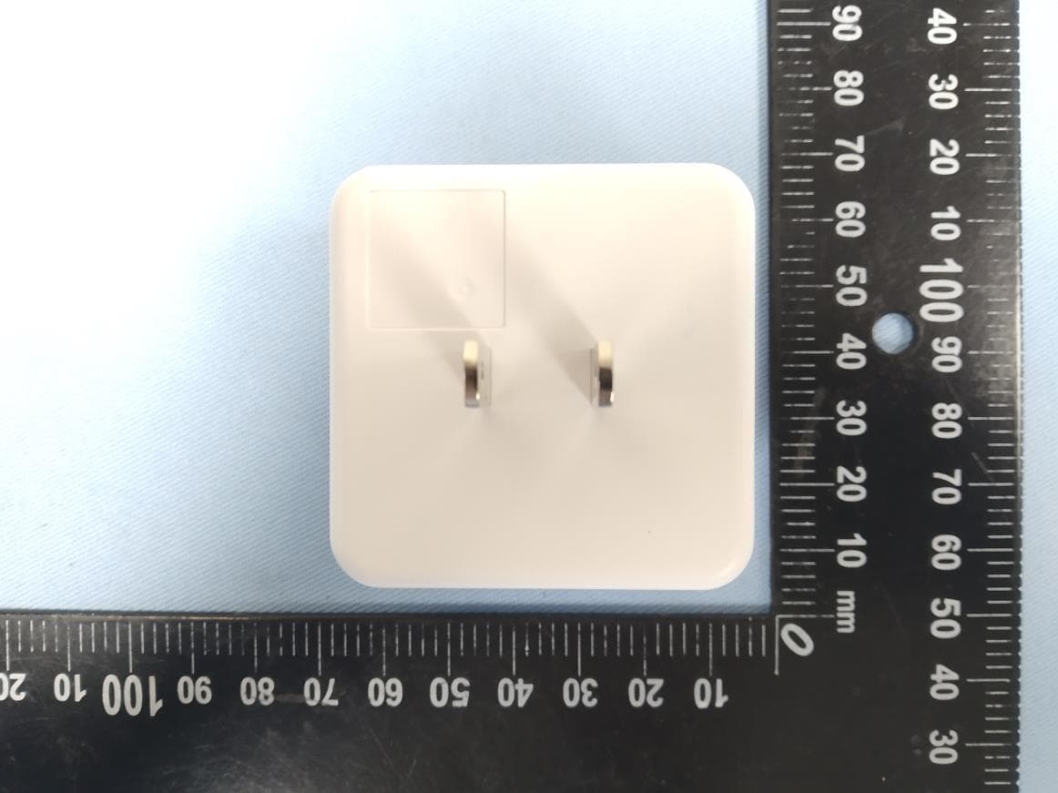
2AQ8A-KP1LINK
Aug 16, 2020Kapture Wifi Bridge
Equipment Class
DTS - Digital Transmission System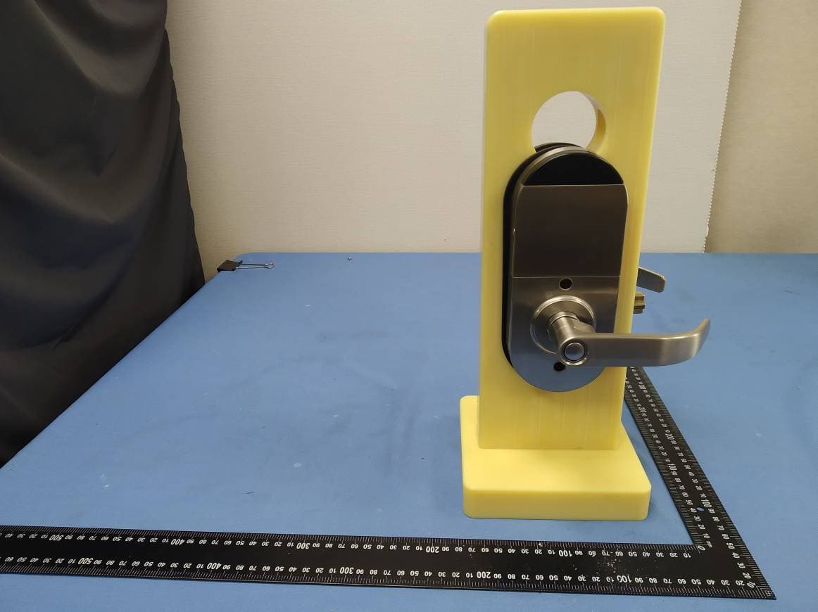
2AQ8A-KE1LNP5C
Mar 07, 2020Enkore
Equipment Class
DTS - Digital Transmission System