2AQ8LPPA1Parsyl Passport
Parsyl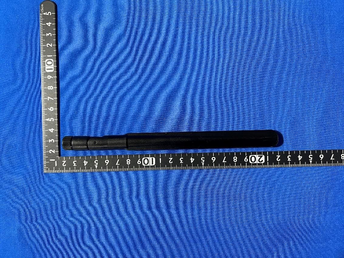
Click to zoom
Application Details
- Equipment Class
- DTS - Digital Transmission System
- Date of Grant
- Aug 15, 2022
- Application Purpose
- Original Equipment
- Date of Application
- Aug 15, 2022
- Equipment Note
- Parsyl Passport
- Frequency Range
- 2412.00000000 - 2462.00000000
- Company
- Parsyl
- Country
- United States
Documents & Files
Document Text
Text extracted from the exhibit documents filed with the FCC. Open a document above to read the original.
Users Manual
LAST EDIT MADE ON 03/03/22 Passport User Guide Device Overview Hardware Setup Connect Device to Networks Device Management Contents Device Overview Passport Description Device Hardware Setup Setting up the Passport Status LEDs Connecting to Networks Download Parsyl Android Mobile App Connect to Passport Connect Passport to Networks Device Management Networks Power Source Scan for Treks Uploads Firmware Version Share Logs with Parsyl Support Need help? Contact us [email protected], via WhatsApp at+1-720-358-8714 (text messages only) or consult our “How to” support articles in our mobile app by tapping on the ? icon. LAST EDIT MADE ON 03/03/22 Device Overview The Parsyl Passport is a gateway device that offloads data from Trek Tab and Trek Pro devices and uploads that data to the web. The Passport provides visibility into sensitive products in both storage and shipment monitoring settings through proximity data offloads. ● Ethernet, Wi-Fi, and Cellular Network connectivity ● Capable of offloading data for up to 400 Treks ● Onboard battery provides up to 12 hours of back-up power ● Wirelessly monitors temperature ● Fast data transfer using Bluetooth 5 ● Up to 100 days of battery life while monitoring ● Configurable LED alarms ● Smaller than a domino ● Durable and water-resistant ● PQS pre-qualified by WHO [Device Image Design Overview] Front, back, left and right diagram of the Passport: Front ● QR Code ● Power, Connectivity and Power LEDs ● Removable Faceplate ● AC Power Input ● Ethernet Port Back ● Quickstart Instructions ● Mounting Brackets ● On/Off Switch Left ● Blue Button Right ● SIM Card Slot LAST EDIT MADE ON 03/03/22 Hardware Setup Connect to External Power Source Attach the included AC adapter to a power source and connect it to the power input on the front of the Passport. Switch the On/Off Switch on the back of the device to turn on the Passport. A red LED indicates the device is using the onboard battery as a power supply, and the Passport is not connected to an external power source. A white LED indicates the device is connected to an external power source. Mount the Passport The Passport can be mounted on a wall using the bracket holes on the back of the device or by placing sticky tape on the back(included with the device). Alternatively, it can be placed on a flat surface. Position the Antennas The Passport receives the strongest signal from Treks when the antennas are positioned upright, perpendicular to the ground. Connect Device to Networks Setting up and connecting the Passport to networks can be done without a Parsyl account. A Parsyl account allows you to access the web and mobile apps and view shipment or storage monitoring data. When your account is created, you will receive a welcome notification via email, SMS or WhatsApp directing you to log in. If you need an account created, please reach out to your company’s ParsylAdministrator or [email protected]. Download the Parsyl Mobile App [Be sure to enable Bluetooth, location and camera permissions when prompted.] 1.Download the Parsyl app from the Google Play or Apple App store. 2.Open the Parsyl app on your Android or iOS device. 3.(Optional Log In) Input your phone number or email address to receive your login code. 4.(Optional Log In) Enter the 6-digit code you received to log in. [You are now logged in!] 5.Tap “Scan Device” to get started. Connect device via Ethernet 1.Connect an Ethernet cable (not provided) to the Ethernet port on the front of the Passport. 2.Press the blue button on the side of the Passport 3.Scan the QR code on the front of the Passport. 4.The Passport will connect to your mobile device. 5.Select Networks from the Detail screen. 6.Ethernet appears in the Networks list with a “Connected” status and a check icon. 7.Tap Ethernet to see IP Address details. Troubleshooting for Ethernet ● Ensure that the Ethernet cable is securely connected at the Passport and at the LAST EDIT MADE ON 03/03/22 other end of the cable. ● Ensure that the modem is turned on and connected to the Internet Ensure the network is configured to allow the Passport to access the internet via <insert our protocols and ports here>. ● Repeat steps 2 & 3 Connect device to Wi-Fi 1.Press the blue button on the side of the Passport 2.Scan the QR code on the front of the Passport 3.Passport will connect to your mobile device. 4.Select Networks from the Detail screen. 5.Wi-Fi appears in the Networks list with a “Not Connected” status and an alert icon. 6.Tap Wi-Fi to enter the network name and password of the network you wish to connect to, then “Join network.” 7.Wi-Fi appears in the Networks list with a “Connected” status followed by the network name and a check icon. Troubleshooting for Wi-Fi ● Check to see that the Wi-Fi network is on and connected to the Internet. ● Verify the network name and password are correct ● Press blue button on the left of the Passport and scan the QR code again Connect to Cellular Network 1.Insert a SIM card into the SIM card slot on the right side of the Passport. 2.Scan the QR code on the front of the Passport 3.The Passport will connect to your mobile device. 4.Select Networks from the Detail screen 5.Cellular appears in the Networks list with a “Connected” status and an alert icon. 6.Tap Cellular to view SIM card details. Troubleshooting for Cellular Network ● Remove and replace the SIM card in the Passport SIM card slot. ● On the Cellular screen, tap “Reset cellular network.” ● Confirm SIM card has been activated LAST EDIT MADE ON 03/03/22 Additional Device Detail Power Source On the Detail screen, Power Source displays the source of power as “Main Power” when the Passport is powered from an external power source and Battery when powered by the onboard rechargeable battery. Once every 30 days, the Passport will automatically switch to the backup battery, allowing the battery to discharge and recharge to maintain battery life. Scan for Treks On the Detail screen, tap “Scan for Treks” to see…
Text truncated - open the document above for the full version.
Cover Letter(s)
Attestation Letter Federal Communications Commission Authorization and Evaluation Division We Name: Parsyl Address: 2825 Larimer Street, Denver CO 80205 USA Declare that the device does not support channel 12 ~ 13 in 2.4GHz band and any non-US channels in all the operational mode(s) for the following product. Product: Parsyl Passport FCC ID: 2AQ8LPPA1 Model: PPA1 Brand: Parsyl Sincerely, _________________ Name: Murat Erdogan Position: Director of Manufacturing Email: [email protected] Date: 2022-07- 14
Cover Letter(s)
Aug 5, 2022 Dear Reader, The Parsyl Passport (Model PPA1) design contains a WiFi and Classic Bluetooth enabled module. That module is made by EspressIf Systems and has part number ESP32-WROOM-32E with FCC ID 2AC7Z-ESP32WROOM32E. The Parsyl Passport, as designed, leverages a Nordic Semiconductor nRF52840 Bluetooth SoC as the primary and only bluetooth subsystem within the product. The Bluetooth components within the ESP32-WROOM-32E module are disabled and will never be used in the end product. As such, we Parsyl, Inc., formally attest that the Classic Bluetooth functionality within the ESP32-WROOM-32E module (FCC ID 2AC7Z-ESP32WROOM32E) is locked out and will not be used. Best regards, Murat Erdogan Director of Manufacturing Parsyl Inc.
Cover Letter(s)
Confidentiality Request Letter Federal Communications Commission Authorization and Evaluation Division FCC ID: 2AQ8LPPA1 Confidentiality Request Pursuant to Sections 0.457 and 0.459 of the Commission’s Rules, we hereby request confidential treatment of information accompanying this application as outlined below: 1. Block Diagram 2. Schematics 3. Operational Description 4. Part List 5. Tune up procedure The above materials contain trade secrets and proprietary information not customarily released to the public. The public disclosure of these matters might be harmful to the applicant and provide unjustified benefits to its competitors. The applicant understands that pursuant to Rule 0.457, disclosure of this application and all accompanying documentation will not be made before the date of the Grant for this application. Sincerely, _________________ Name: Murat Erdogan Position: Director of Manufacturing Email: [email protected] Date: 2022-07- 14
Cover Letter(s)
Declaration of Authorization We Name: Parsyl Address: 2825 Larimer Street, Denver CO 80205 USA Declare that: Name Representative of agent: Marlin Chen Agent Company name: MRT Technology (Suzhou) Co., Ltd Address: D8 Building, Youxin Industrial Park, No.2 Tian'edang Rd., Wuzhong Economic Development Zone City: Suzhou Country: China is authorized to apply for Certification of the following product(s): Product: Parsyl Passport FCC ID: 2AQ8LPPA1 Model: PPA1 Brand: Parsyl Sincerely, _________________ Name: Murat Erdogan Position: Director of Manufacturing Email: [email protected] Date: 2022-07- 14
Cover Letter(s)
Declaration of Conformity We Name: Parsyl Address: 2825 Larimer Street, Denver CO 80205 USA Declare that: Product: Parsyl Passport FCC ID: 2AQ8LPPA1 Model: PPA1 Brand: Parsyl Product which bears the above FCC ID is also compliant with the FCC requirements for sDOC. And the sDOC procedure shall be carried out prior to marketing the device in the US. Sincerely, _________________ Name: Murat Erdogan Position: Director of Manufacturing Email: [email protected] Date: 2022-07- 14
Cover Letter(s)
Short Term Confidentiality Request Letter Federal Communications Commission Authorization and Evaluation Division FCC ID: 2AQ8LPPA1 Pursuant to sections 0.457 and 0.459 of CFR 47 Commission’s policy and to avoid premature release of sensitive information prior to marketing or release of the product to the public, the applicant requests the following documents contained in this certification application be temporarily withheld from public disclosure for an initial period of 180 days: 1. External Photos 2. Internal Photos 3. Test Setup Photos 4. User Manual The above materials contain trade secrets and proprietary information not customarily released to the public. The public disclosure of these matters might be harmful to the applicant and provide unjustified benefits to its competitors. The applicant understands that pursuant to Rule 0.457, disclosure of this application and all accompanying documentation will not be made before the date of the Grant for this application. Sincerely, ________________ Name: Murat Erdogan Position: Director of Manufacturing Email: [email protected] Date: 2022-07- 14
External Photos
Report No.: 2203RSU047-UE 1 of 7 External Photograph (1) EUT Photo (2) EUT Photo Report No.: 2203RSU047-UE 2 of 7 (3) EUT Photo (4) EUT Photo Report No.: 2203RSU047-UE 3 of 7 (5) EUT Photo (6) EUT Photo Report No.: 2203RSU047-UE 4 of 7 (7) EUT Photo (8) EUT Photo Report No.: 2203RSU047-UE 5 of 7 (9) EUT Photo (10) EUT Photo Report No.: 2203RSU047-UE 6 of 7 (11) EUT Photo (12) EUT Photo Report No.: 2203RSU047-UE 7 of 7 (13) EUT Photo
ID Label/Location Info
0.7in 18.7mm 1.0in 26.1mm Parsyl Passport - back view FCC ID label 0.4in 10.0mm 1.3in 34.0mm FCC ID label - zoomed view antenna on the left only partially shown
Internal Photos
Report No.: 2203RSU047-UE 1 of 12 Internal Photograph (1) EUT Photo (2) EUT Photo Report No.: 2203RSU047-UE 2 of 12 (3) EUT Photo (4) EUT Photo Report No.: 2203RSU047-UE 3 of 12 (5) EUT Photo (6) EUT Photo Report No.: 2203RSU047-UE 4 of 12 (7) EUT Photo (8) EUT Photo Report No.: 2203RSU047-UE 5 of 12 (9) EUT Photo (10) EUT Photo Report No.: 2203RSU047-UE 6 of 12 (11) EUT Photo (12) EUT Photo Report No.: 2203RSU047-UE 7 of 12 (13) EUT Photo (14) EUT Photo Report No.: 2203RSU047-UE 8 of 12 (15) EUT Photo (16) EUT Photo Report No.: 2203RSU047-UE 9 of 12 (17) EUT Photo (18) EUT Photo Report No.: 2203RSU047-UE 10 of 12 (19) EUT Photo (20) EUT Photo Report No.: 2203RSU047-UE 11 of 12 (21) EUT Photo (22) EUT Photo Report No.: 2203RSU047-UE 12 of 12 (23) EUT Photo (24) EUT Photo
Test Report
MRT Technology (Suzhou) Co., Ltd Report No.: 2203RSU047-U2 Phone: +86-512-66308358 Report Version: V01 Web: www.mrt-cert.com Issue Date: 2022-07-31 Template Version:0.0 1 of 62 RF MEASUREMENT REPORT FCC ID: 2AQ8LPPA1 Applicant: Parsyl Product: Parsyl Passport Model No.: PPA1 Brand Name: Parsyl FCC Classification: Digital Transmission System (DTS) FCC Rule Part(s): Part 15 Subpart C (Section 15.247) Result: Complies Test Date: 2022-06-10 ~ 2022-06-15 Reviewed By: Sunny Sun Approved By: Robin Wu The test results relate only to the samples tested. This equipment has been shown to be capable of compliance with the applicable technical standards as indicated in the measurement report and was tested in accordance with the measurement procedures specified in ANSI C63.10-2013. Test results reported herein relate only to the item(s) tested. The test report shall not be reproduced except in full without the written approval of MRT Technology (Suzhou) Co., Ltd. Report No.: 2203RSU047-U2 2 of 62 Revision History Report No. Version Description Issue Date Note 2203RSU047-U2 Rev. 01 Initial Report 2022-07-31 Valid Report No.: 2203RSU047-U2 3 of 62 CONTENTS Description Page 1. General Information ................................................................................................................................ 5 1.1. Applicant ...................................................................................................................................... 5 1.2. Manufacturer ................................................................................................................................ 5 1.3. Testing Facility ............................................................................................................................. 5 1.4. Product Information ...................................................................................................................... 6 1.5. Radio Specification under Test .................................................................................................... 6 1.6. Antennas Details .......................................................................................................................... 7 1.7. Working Frequencies ................................................................................................................... 7 2. Test Configuration ................................................................................................................................... 8 2.1. Test System Connection Diagram................................................................................................ 8 2.2. Test Software ............................................................................................................................... 8 2.3. Applied Standards ........................................................................................................................ 8 2.4. Test Environment Condition ......................................................................................................... 9 3. Antenna Requirements ......................................................................................................................... 10 4. Measuring Instrument ........................................................................................................................... 11 5. Decision Rules and Measurement Uncertainty .................................................................................. 12 5.1. Decision Rules ........................................................................................................................... 12 5.2. Measurement Uncertainty .......................................................................................................... 12 6. Test Result .............................................................................................................................................. 13 6.1. Summary .................................................................................................................................... 13 6.2. 6dB Bandwidth Measurement .................................................................................................... 14 6.2.1. Test Limit .................................................................................................................................... 14 6.2.2. Test Procedure ........................................................................................................................... 14 6.2.3. Test Setting ................................................................................................................................ 14 6.2.4. Test Setup .................................................................................................................................. 14 6.2.5. Test Result ................................................................................................................................. 14 6.3. Output Power Measurement ...................................................................................................... 15 6.3.1. Test Limit .................................................................................................................................... 15 6.3.2. Test Procedure ........................................................................................................................... 15 6.3.3. Test Setting ................................................................................................................................ 15 6.3.4. Test Setup .................................................................................................................................. 16 6.3.5. Test Result ................................................................................................................................. 16 6.4. Power Spectral Density Measurement .............................................................…
Text truncated - open the document above for the full version.
Test Report
MRT Technology (Suzhou) Co., Ltd Report No.:2203RSU047-U3 Phone: +86-512-66308358 Report Version: V01 Web: www.mrt-cert.com Issue Date: 2022-07-31 Template Version:0.0 1 of 46 RF MEASUREMENT REPORT FCC ID: 2AQ8LPPA1 Applicant: Parsyl Product: Parsyl Passport Model No.: PPA1 Brand Name: Parsyl FCC Classification: Digital Transmission System (DTS) FCC Rule Part(s): Part 15 Subpart C (Section 15.247) Result: Complies Test Date: 2022-04-17 Reviewed By: Sunny Sun Approved By: Robin Wu The test results relate only to the samples tested. This equipment has been shown to be capable of compliance with the applicable technical standards as indicated in the measurement report and was tested in accordance with the measurement procedures specified in ANSI C63.10-2013. Test results reported herein relate only to the item(s) tested. The test report shall not be reproduced except in full without the written approval of MRT Technology (Suzhou) Co., Ltd. Report No.: 2203RSU047-U3 2 of 46 Revision History Report No. Version Description Issue Date Note 2203RSU047-U3 Rev. 01 Initial Report 2022-07-31 Valid Report No.: 2203RSU047-U3 3 of 46 CONTENTS Description Page 1. General Information ................................................................................................................................ 5 1.1. Applicant ...................................................................................................................................... 5 1.2. Manufacturer ................................................................................................................................ 5 1.3. Testing Facility ............................................................................................................................. 5 1.4. Product Information ...................................................................................................................... 6 1.5. Radio Specification ...................................................................................................................... 6 1.6. Antennas Details .......................................................................................................................... 7 1.7. Working Frequencies ................................................................................................................... 7 2. Test Configuration ................................................................................................................................... 8 2.1. Test Mode ..................................................................................................................................... 8 2.2. Test System Connection Diagram................................................................................................ 8 2.3. Test System Details ..................................................................................................................... 8 2.4. Test Software ............................................................................................................................... 8 2.5. Applied Standards ........................................................................................................................ 9 2.6. Test Environment Condition ......................................................................................................... 9 3. Antenna Requirements ......................................................................................................................... 10 4. Measuring Instrument ........................................................................................................................... 11 5. Measurement Uncertainty ..................................................................................................................... 12 6. Test Result .............................................................................................................................................. 13 6.1. Summary .................................................................................................................................... 13 6.2. Output Power Measurement ...................................................................................................... 14 6.2.1. Test Limit .................................................................................................................................... 14 6.2.2. Test Procedure ........................................................................................................................... 14 6.2.3. Test Setting ................................................................................................................................ 14 6.2.4. Test Setup .................................................................................................................................. 16 6.2.5. Test Result ................................................................................................................................. 16 6.3. Radiated Spurious Emission Measurement ............................................................................... 17 6.3.1. Test Limit .................................................................................................................................... 17 6.3.2. Test Procedure ........................................................................................................................... 17 6.3.3. Test Setting ................................................................................................................................ 17 6.3.4. Test Setup .................................................................................................................................. 19 6.3.5. Test Result ................................................................................................................................. 19 6.4. Radiated Restricted Band Edge Measurement ...........................................…
Text truncated - open the document above for the full version.
Test Report
Note: This test report is prepared for the customer shown above and for the equipment described herein. It may not be duplicated or used in part without prior written consent from Bay Area Compliance Laboratories Corp. FCC PART 15.247 TEST REPORT For ESPRESSIF SYSTEMS (SHANGHAI) PTE LTD 456 Bibo Road Room A201, Shanghai, China FCC ID: 2AC7Z-ESPWROOM32 Report Type: Original Report Product Type: WIFI &Bluetooth Module Test Engineer: Peter Jiang Report Number: RKS161017001-00B Report Date: 2016-11-16 Reviewed By: Jesse Huang EMC Manager Prepared By: Bay Area Compliance Laboratories Corp. (Kunshan) Chenghu Road,Kunshan Development Zone No.248,Kunshan, Jiangsu, China Tel: +86-0512-86175000 Fax: +86-0512-88934268 www.baclcorp.com.cn Bay Area Compliance Laboratories Corp. (Kunshan) Report No.: RKS161017001-00B FCC Part 15.247 Page 2 of 71 TABLE OF CONTENTS GENERAL INFORMATION ....................................................................................................................................... 4 PRODUCT DESCRIPTION FOR EQUIPMENT UNDER TEST (EUT) ..................................................................................... 4 OBJECTIVE ................................................................................................................................................................... 4 RELATED SUBMITTAL(S)/GRANT(S) ............................................................................................................................. 4 TEST METHODOLOGY .................................................................................................................................................. 4 TEST FACILITY ............................................................................................................................................................. 5 SYSTEM TEST CONFIGURATION .......................................................................................................................... 6 DESCRIPTION OF TEST CONFIGURATION ...................................................................................................................... 6 EQUIPMENT MODIFICATIONS ....................................................................................................................................... 6 EUT EXERCISE SOFTWARE .......................................................................................................................................... 7 SUPPORT EQUIPMENT LIST AND DETAILS .................................................................................................................... 8 EXTERNAL I/O CABLE .................................................................................................................................................. 8 BLOCK DIAGRAM OF TEST SETUP ................................................................................................................................ 8 SUMMARY OF TEST RESULTS ............................................................................................................................... 9 FCC§15.247 (i), §1.1310& §2.1091 –Maximum Permissible Exposure (MPE) ............................................................ 10 APPLICABLE STANDARD ............................................................................................................................................ 10 FCC §15.203 - ANTENNA REQUIREMENT ........................................................................................................... 11 APPLICABLE STANDARD ............................................................................................................................................ 11 ANTENNA CONNECTOR CONSTRUCTION .................................................................................................................... 11 FCC §15.207 (a) – AC LINE CONDUCTED EMISSIONS ..................................................................................... 12 APPLICABLE STANDARD ............................................................................................................................................ 12 MEASUREMENT UNCERTAINTY .................................................................................................................................. 12 EUT SETUP ................................................................................................................................................................ 12 EMI TEST RECEIVER SETUP ....................................................................................................................................... 13 TEST PROCEDURE ...................................................................................................................................................... 13 TEST EQUIPMENT LIST AND DETAILS ......................................................................................................................... 13 CORRECTED FACTOR & MARGIN CALCULATION ....................................................................................................... 13 TEST RESULTS SUMMARY .......................................................................................................................................... 14 TEST DATA ................................................................................................................................................................ 14 FCC §15.209, §15.205 & §15.247(d) - SPURIOUS EMISSIONS ............................................................................. 19 APPLICABLE STANDARD ............................................................................................................................................ 19 MEASUREMENT UNCERTAINTY .................................................................................................................................. 19 EUT SETUP ..........................................................................…
Text truncated - open the document above for the full version.
Test Report
MRT Technology (Suzhou) Co., Ltd Report No.: 2203RSU047-U4 Phone: +86-512-66308358 Report Version: V01 Web: www.mrt-cert.com Issue Date: 2022-07-31 Template Version:0.0 1 of 12 RF Exposure Evaluation Declaration F…
Text truncated - open the document above for the full version.
Contact Information
Applicant
Murat Erdogan(Director of Manufacturing)
Test Firm
MRT Technology (Suzhou) Co., Ltd.Mr. Marlin Chen
[email protected]8651266308358
Technical Specifications
| # | Rule Parts | Frequency Range | Power Output |
|---|---|---|---|
| 2 | 15C | 2.41 GHz - 2.46 GHz | 63.00 mW |
Other Applications from Parsyl
2AQ8LTREKC2
Jul 11, 2021Temperature Data logger with Bluetooth
Equipment Class
DTS - Digital Transmission System
2AQ8LTREKC1
Mar 15, 2021Temperature Data logger with Bluetooth Low Energy
Equipment Class
DTS - Digital Transmission System