2AQM7-36BLBB-3.6CA-b is a Vehicle Gateway. Its purpose is to act as the primary gateway between various pieces of hardware and software in a motor vehicle and the Motive Technologies database back-end in the cloud.
Motive Technologies, Inc.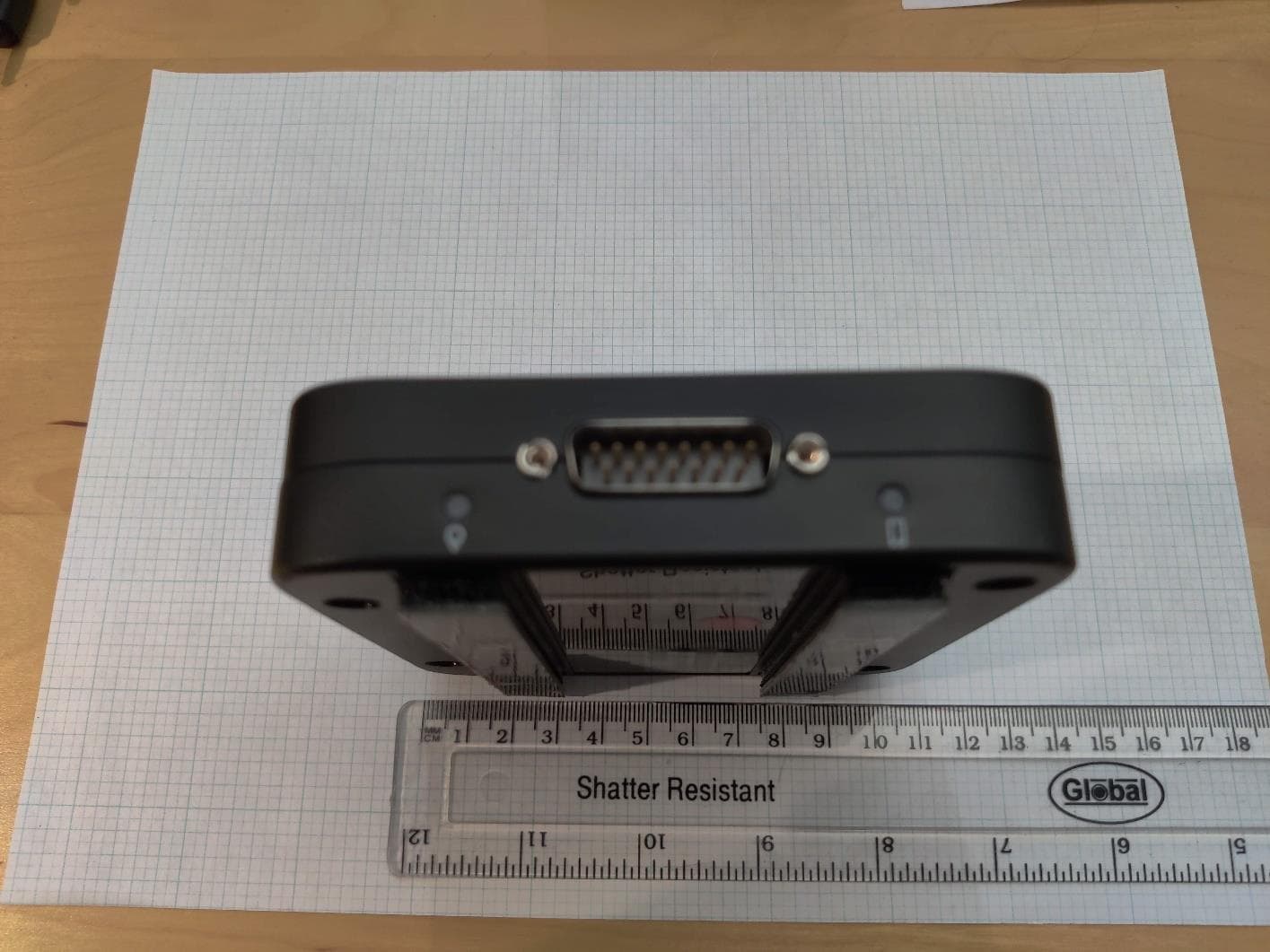
Click to zoom
Application Details
- Equipment Class
- DSS - Part 15 Spread Spectrum Transmitter
- Date of Grant
- Sep 27, 2022
- Application Purpose
- Original Equipment
- Date of Application
- Sep 26, 2022
- Equipment Note
- LBB-3.6CA-b is a Vehicle Gateway. Its purpose is to act as the primary gateway between various pieces of hardware and software in a motor vehicle and the Motive Technologies database back-end in the cloud.
- Frequency Range
- 2402.00000000 - 2480.00000000
- Company
- Motive Technologies, Inc.
- Country
- United States
Documents & Files
Document Text
Text extracted from the exhibit documents filed with the FCC. Open a document above to read the original.
Users Manual
Environmental Sensor (ES- ) Installation guide Français se trouve au dos. Vehicle Gateway Installation manual English Vehicle Gateway Alcohol wipes Zip ties ALCOHOL Scan this code or visit gomotive.com/vg-install for additional support, including step-by-step instructions in multiple languages and tips about mounting and cabling. Table of contentsWhat’s in the box Before you begin Installing in a pickup or van Installing in a large truck Activation Understanding the LEDs Troubleshooting 1 2 4 12 20 21 28 What's in the box Cables shipped separately You should’ve also received the appropriate cable to match your vehicle. For cable-specific guidance, visit: gomotive.com/vg-install 1 Before you begin1 Log into gomotive.com 2 Go to the Admin section You’ll need to be set up as a fleet admin to add/edit vehicles and assign the Vehicle Gateway. If you don’t see the Admin section a ter logging in, contact a fleet admin. NOTE: If you are installing, but not activating, the Vehicle Gateway, you can skip to page 4. 3 Add a vehicle From the Admin section, select “Vehicles” and either add a new vehicle or search for an existing vehicle to edit. 4 Assign your Vehicle Gateway In the vehicle’s profile, add (or update) the Vehicle Gateway’s serial number (printed on the back of the device and on the outside of the packaging). Make sure to hit “Save” when you’re done. 5 Add a new driver to your account From the Admin section of the Motive Fleet Dashboard, go to the Drivers tab and select “Add Driver” to begin creating their account. This will generate a new login that the driver will use to sign into the Motive Driver App and connect to the Vehicle Gateway. 6 Download the Motive Driver App Log in with the driver account credentials. You’re now ready to install your Vehicle Gateway! 2 If you are the driver or manage driver accounts, follow these additional steps. 3 Watch installation video Installing in a pickup or van There are 2 types of installations: Basic install The fastest way to get up and running. Continue to the next page Covert install Keeps your Vehicle Gateway concealed from view, which can help deter the t or tampering. Skip to page 7 54 On the dashboard Avoid placing near obstructions like air vents or metal which can cause interference. Behind the diagnostic port Use the adhesive strips and zip ties to secure the device. Basic install Here are some examples of where the Vehicle Gateway can be mounted. Exact placement will depend on your vehicle make/model. 7 Covert installations Here are some examples of covert installation locations in light duty vehicles. The locations in your vehicle may vary somewhat from those shown below. Above the glove box Many vehicles have some space above or behind the glove box that can be used to place the Vehicle Gateway. Behind the multimedia screen Many vehicles have cavities behind or along the sides of the multimedia touch screen that can be used to place the Vehicle Gateway. 16 Basic install cable options Before deciding on cable options, first locate the diagnostic port (OBD-II) which should be to the le t of the footwell or behind a removable plastic panel. Direct connection The fastest way to get up and running. Skip to page 8 Y spli ter cable Leaves the port accessible and facilitates a covert installation. Please review important safety and warranty information at the end of this manual. 4 4 98 Covert install cable options First locate the diagnostic port (OBD-II), which should be to the le t of the footwell or hidden behind a removable plastic panel. For covert installations, you’ll want to use the Y spli ter cable. Y spli ter cable This option leaves the port accessible. Please see important safety and warranty information at the end of this manual. Mounting instructions A ter connecting to the vehicle, plug the other end of the cable into the Vehicle Gateway. Use the included alcohol swab to thoroughly clean the area where you’ve chosen to position your Vehicle Gateway. If you removed a panel during installation, rea tach it now. 11 Activation instructions Mounting instructions (continued) Peel o f the adhesive backing on the Vehicle Gateway, then mount it in the desired location. Use the zip ties to secure the cables in place. Are both of the LED lights illuminated? If not, turn on the vehicle’s ignition. The le t-side LED will change to green to show a cellular/GPS connection has been established (this may take several minutes). Drivers who are tracking Hours of Service (HOS) will need to open the Motive Driver App and log in with their credentials. The Motive Driver App will ask you to pair your mobile device with the Vehicle Gateway and select the vehicle you’ve just performed the installation in. When the right-side LED turns green, the app has successfully paired with the vehicle. 10 Watch installation video There are 2 types of installations: Basic install The fastest way to get up and running. Continue to the next page Covert install Keeps your Vehicle Gateway concealed from view, which can help deter the t or tampering. Skip to page 15 Installing in a large truck 1312 On the dashboard The fastest way to get up and running. Continue to the next page Behind the diagnostic port Placing the Vehicle Gateway underneath the dashboard and behind the diagnostic port is an easy way to install and keep things out of the driver’s way. Basic install Here are some examples of where the Vehicle Gateway can be mounted. Exact placement will depend on your vehicle make/model. Covert install Basic install cable options Once you’ve decided on the location, you’ll need to determine which type of cable to use. Motive strongly recommends using cables provided by Motive for use with the Motive Vehicle Gateway. To the extent you choose to install the Motive Vehicle Gateway using a cable not provided by Motive, your device will no longer be covered by Motive's limited hardware warranty and Motive will not be responsible or liable for any resulting injury, loss, da…
Text truncated - open the document above for the full version.
Attestation Statements
Subject: Validity of Test Results from Testing / Certification of the Integrated Module To Whom It May Concern: We, Motive Technologies, Inc., 55 Hawthorn St. Suite 400, San Francisco CA 94105, do hereby declare that that the test results from conducted tests applied to the radio module: Manufacturer: Laird Connectivity LLC Model: LSR 450-0159R FCC ID: TFB-1003 IC: 5969A-1003 and as reported in module test report(s): Report Number: # 316050 DTS, Issue Date: 4-20-16 (Technology 2.4GHz WiFi) Report Number: #316050 FHSS, Issue Date: 4/20/16 (Technology BT) (BLE mode supported in module is not supported in LBB-3.6CA-b and will be disabled in LBB- 3.6CA-b such that BLE mode is not accessible to end user), and also that the test results from conducted tests applied to the radio module: Manufacturer: Sierra Wireless Inc. Model: RC7612 FCC ID: N7NRC76C IC: 2417C-RC76C and as reported in module test report(s): Report Number: Report No.: BTL-FCCP-1-2203T030, BTL-FCCP-2-2203T030, Report No.: BTL-FCCP-3-2203T030 Issue Date: 2022/6/21 (Technology: UMTS & LTE) both of which modules are incorporated in our host equipment: Manufacturer: Motive Technologies, Inc. Model: LBB-3.6CA-b FCC ID: 2AQM7-36B IC: 24516-36B accurately represent the test results under the new conditions when the identified radio module is integrated in the identified host equipment. By integration of the said radio module into the identified host equipment, no changes were made to it or by external adaptation circuitry that impacts the validity of the results of the original module’s test reports; hence conducted signal measurements in the above listed reports also apply to Product/Model: LBB- 3.6CA-b Sincerely, Daniel A. Nelson Director of Compliance
Attestation Statements
55 Hawthorne Street, Floor 4 San Francisco, CA 94105 gomotive.com Letter of Authorization and Anti- Drug Statement Applicant Name: Motive Technologies, Inc. Address: 55 Hawthorn St., Suite 400, San Francisco, CA 94105 Product Name: Vehicle Gateway LBB-3.6CA Model Number: LBB-3.6CA FCC ID: 2AQM7-36B We authorize: CETECOM Inc., to act on our behalf on all matters concerning the above-named equipment. We declare that CETECOM Inc. is allowed to forward all information related to the approval project to the Federal Communications Commission and discuss any issues concerning the approval application. The applicant must certify that neither the applicant nor any party to the application is subject to a denial of Federal benefits, that include FCC benefits, pursuant to Section 5301 of the Anti-Drug Abuse Act of 1988, 21 U.S.C. § 862 because of a conviction for possession or distribution of a controlled substance. See 47 CFR 1.2002(b) for the definition of a "party" for these purposes. Does the applicant or authorized agent so certify? ☒ Yes I certify that I am authorized to sign this application. All of the statements herein and the exhibits attached hereto, are true and correct to the best of my knowledge and belief. In accepting a Grant of Equipment Authorization as a result of the representations made in this application, the applicant is responsible for (1) labeling the equipment with the exact FCC ID specified in this application, (2) compliance statement labeling pursuant to the applicable rules, and (3) compliance of the equipment with the applicable technical rules. If the applicant is not the actual manufacturer of the equipment, appropriate arrangements have been made with the manufacturer to ensure that production units of this equipment will continue to comply with the FCC's technical requirements. Authorizing an agent to sign this application, is done solely at the applicant's discretion; however, the applicant remains responsible for all statements in this application. If an agent has signed this application on behalf of the applicant, a written letter of authorization which includes information to enable the agent to respond to the above section 5301 (Anti-Drug Abuse) Certification statement has been provided by the applicant. It is understood that the letter of authorization must be submitted to the FCC upon request, and that the FCC reserves the right to contact the applicant directly at any time. Signature of Authorized Person Filing: Title: Director of Compliance Date: August 8, 2022
Cover Letter(s)
Federal Communications Commission Equipment Authorization Division 7435 Oakland Mills Road Columbia, MD 21048 Date: 8/9/2022 Subject: Request for Permanent Confidentiality FCC ID: 2AQM7-36B To Whom It May Concern: In accordance with §0.457(d) and §0.459 of CFR 47, and KDB 726920, Motive Technologies, Inc. hereby requests permanent confidentiality for documents filed under the following exhibit types: 1. Block Diagram 2. Schematic Diagram 3. Part List 4. Operational Description These items contain detailed system and equipment description and related information about the product which Motive Technologies, Inc. considers to be proprietary, confidential and a custom design which otherwise would not be released to the general public. Since this design is a basis from which future technological products will evolve, Motive Technologies, Inc. also feels that this information would be of benefit to its competitors, and that the disclosure of the information in these exhibits would give our competitors an unfair advantage in the market. We are aware that exhibit types cover letters, attestations, label document, test reports, RF exposure information (SAR and MPE reports), cannot be requested to be classified confidential and are thus subject to publication, as will be documents of all other exhibit types for which we have not requested a confidentiality classification. Best Regards, Name: Daniel A. Nelson Title: Director of Compliance Company Name: Motive Technologies, Inc. Address: 55 Hawthorne St Suite 400 San Francisco, CA 94105
Cover Letter(s)
Federal Communications Commission Equipment Authorization Division 7435 Oakland Mills Road Columbia, MD 21048 Date: 8/9/2022 Subject: Request for Short Term Confidentiality FCC-ID: 2AQM7-36B To Whom It May Concern: In accordance with §0.457(d) and §0.459 of CFR 47, Motive Technologies, Inc. hereby requests short term confidentiality for documents filed under the following exhibit types: 1. External Photographs 2. Internal Photographs 3. User / Instruction Manual 4. Test Set-up Photographs until the product will be publicly announced. Short term confidentiality release date / period: 180 days from grant issue date These items contain detailed system and equipment description and related information about the product which Motive Technologies, Inc. Considers to be proprietary, confidential and a custom design which otherwise would not be released to the general public. Since this design is a basis from which future technological products will evolve, Motive Technologies, Inc. also feels that this information would be of benefit to its competitors, and that the disclosure of the information in these exhibits would give our competitors an unfair advantage in the market. We are informed and aware of our obligation that we have to inform the involved TCB in written and in due time if we intend to market the product prior to the above specified confidentiality release date so that the short term confidentiality classification can be reset prior to product launch. We are aware that exhibit types cover letters, attestations, label document, test reports, RF exposure information (SAR and MPE reports), cannot be requested to be classified confidential and are thus subject to publication, as will be documents of all other exhibit types for which we have not requested a confidentiality classification. Best Regards, Name: Daniel A. Nelson Title: Director of Quality and Compliance Company Name: Motive Technologies, Inc. Address: 55 Hawthorne St Suite 400 San Francisco, CA 94105
RF Exposure Info
Radio Frequency Exposure Evaluation Report FOR: Motive Technologies, Inc. Model Name: LBB-3.6CA-b Product Description: LBB-3.6CA-b is a Vehicle Gateway. Its purpose is to act as the primary gateway between various pieces of hardware and software in a motor vehicle and the Motive Technologies database back-end in the cloud. FCC ID: 2AQM7-36B IC ID: 24516-36B Applied Rules and Standards: CFR Part Part1 (1.1307 &1.1310), Part 2 (2.1091), FCC KDB 447498 D01 General RF Exposure Guidance v06 ISED RSS-102 Issue 5 Report number: EMC_KPTRK-030-22001_FCC_ISED_MPE DATE: 08-16-2022 CETECOM Inc. 411 Dixon Landing Road Milpitas, CA 95035 U.S.A. Phone: + 1 (408) 586 6200 Fax: + 1 (408) 586 6299 E-mail: [email protected] http://www.cetecom.com CETECOM Inc. is a Delaware Corporation with Corporation number: 2905571 V5.0 2015-10-27 © Copyright by CETECOM Test Report #: EMC_KPTRK-030-22001_FCC_ISED_MPE FCC ID: 2AQM7-36B Date of Report 0B-16-2022 Page 2 of 8 IC ID: 24516-36B Page 2 of 8 1 Assessment This RF Exposure evaluation report provides evidence for compliance of the below identified device with the RF Exposure limits for mobile devices as defined in FCC CFR Part 1 (1.1307 &1.1310), Part 2 (2.1091) and ISED standard RSS-102 issue 5 under worst case conditions (measured or rated RF output power, antenna gain, distance towards human body, multiple transmitter information as presented by the applicant). In addition, maximum antenna gain or minimum distance towards the human body is calculated respectively, where relevant. The device meets the limits as stipulated by the above given FCC and ISED rule parts based on available specifications for worst case conditions at 20cm distance to the body. Company Description Model # Motive Technologies, Inc. LBB-3.6CA-b is a Vehicle Gateway. Its purpose is to act as the primary gateway between various pieces of hardware and software in a motor vehicle and the Motive Technologies database back-end in the cloud. LBB-3.6CA-b Report reviewed by: TCB Evaluator 08-16-2022 Compliance Kevin Wang (Lab Manager) Date Section Name Signature Responsible for the Report: 08-16-2022 Compliance Kris Lazarov (Test Engineer) Date Section Name Signature The test results of this test report relate exclusively to the test item specified in Section3. CETECOM Inc. USA does not assume responsibility for any conclusions and generalizations drawn from the test results with regard to other specimens or samples of the type of the equipment represented by the test item. The test report may only be reproduced or published in full. Reproduction or publication of extracts from the report requires the prior written approval of CETECOM Inc. USA. Test Report #: EMC_KPTRK-030-22001_FCC_ISED_MPE FCC ID: 2AQM7-36B Date of Report 0B-16-2022 Page 3 of 8 IC ID: 24516-36B Page 3 of 8 2 Administrative Data 2.1 Identification of the Testing Laboratory Issuing the Test Report Company Name: CETECOM Inc. Department: Compliance Street Address: 411 Dixon Landing Road City/Zip Code Milpitas, CA 95035 Country USA Telephone: +1 (408) 586 6200 Fax: +1 (408) 586 6299 Lab Manager: Kevin Wang Responsible Project Leader: Akanksha Baskaran 2.2 Identification of the Client / Manufacturer Client’s Name: Motive Technologies, Inc. Street Address: 55 Hawthorne Street #400 City/Zip Code San Francisco, California 94105 Country USA 2.3 Identification of the Manufacturer Manufacturer’s Name: Same as Client Manufacturers Address: City/Zip Code Country Test Report #: EMC_KPTRK-030-22001_FCC_ISED_MPE FCC ID: 2AQM7-36B Date of Report 0B-16-2022 Page 4 of 8 IC ID: 24516-36B Page 4 of 8 3 Equipment under Assessment Marketing name: LBB-3.6CA-b HW Version : 1 SW Version : 75012 Hardware Version Identification Number (HVIN): LBB-3.6CA-b Product Marketing Name (PMN): Vehicle Gateway Regulatory Band: Cellular Module: WCDMA/UMTS FDD BAND II: 1852.4 ~ 1907.6 MHz WCDMA/UMTS FDD BAND IV: 1712.4 ~ 1752.6 MHz WCDMA/UMTS FDD BAND V: 826.4 ~ 846.6 MHz LTE BAND 2: 1850 ~ 1910 MHz LTE BAND 4: 1710 ~ 1755 MHz LTE BAND 5: 824 ~ 849 MHz LTE BAND 12: 699 ~ 716 MHz LTE BAND 13: 777 ~ 787 MHz BT: Nominal band: 2400 MHz – 2483.5 MHz Center to center: 2402 MHz (ch 0) – 2480 MHz (ch 78), 79 Channels WLAN : Nominal band: 2400 MHz – 2483.5 MHz; Center to center: 2412 MHz (ch 1) – 2462 MHz (ch 11), 11 channels Integrated Module Info: WCDMA, LTE Manufacture: Sierra Wireless Module name/number: RC7612 FCC ID: N7NRC76C IC ID: 2417C-RC76C WLAN, BT Manufacture: Laird Connectivity Module name/number: LSR 450-0159R FCC ID: TFB-1003 IC ID: 5969A-1003 Antenna Type: Cellular: Model Name : WCDMA/LTE Main Antenna Part No. : CWT0020P Type & Gain : Inverted–F Antenna (IFA), Max Gain 2.7dBi BT, WLAN: Model Name : LTE Diversity with GPS & Wi-Fi Antenna Part No. : CWT0031P BT/WiFi Type & Gain: Inverted F Antenna (IFA), 1.92 dBi Maximum Conducted Output Power: Cellular: From modular grant [Watts]: WCDMA Band II: 0.170 WCDMA Band IV: 0.181 WCDMA Band V: 0.197 LTE Band 2: 0.191 LTE Band 4: 0.170 LTE Band 5: 0.171 LTE Band 12: 0.169 LTE Band 13: 0.169 BT: From modular grant [Watts]: 0.0078 WLAN: From modular grant [Watts]: 0.2519 Power Supply/ Rated Operating Voltage Range: Vmin: 6 VDC/ Vnom: 12 VDC / Vmax: 32 VDC Operating Temperature Range: Low -20⁰C, Nominal 20⁰C, High 85⁰C Sample Revision: Prototype Unit; Production Unit; Pre-Production Test Report #: EMC_KPTRK-030-22001_FCC_ISED_MPE FCC ID: 2AQM7-36B Date of Report 0B-16-2022 Page 5 of 8 IC ID: 24516-36B Page 5 of 8 4 RF Exposure Evaluation Methods 4.1 RF Exposure Test Exemptions for Single Source 4.1.1 FCC § 2.1091 Radiofrequency radiation exposure evaluation: mobile devices. Single RF sources as defined in paragraph (b)(2) of FCC § 2.1091 is exempt if the ERP (watts) is no more than the calculated value prescribed for that frequency. General frequency and separation-distance dependent MPE-based effective radiated power ERP thresho…
Text truncated - open the document above for the full version.
Test Report
A2LA Accredited IC recognized # 3462B-2 CABID: US0187 CETECOM Inc. 411 Dixon Landing Road Milpitas, CA 95035 U.S.A. Phone: + 1 (408) 586 6200 Fax: + 1 (408) 586 6299 E-mail: [email protected] http://www.cetecom.com CETECOM Inc. is a Delaware Corporation with Corporation number: 2905571 © Copyright by CETECOM FCC / ISED Test Report FOR: Motive Technologies, Inc. Model Name: LBB-3.6CA-b Product Description: LBB-3.6CA-b is a Vehicle Gateway. Its purpose is to act as the primary gateway between various pieces of hardware and software in a motor vehicle and the Motive Technologies database back- end in the cloud. FCC ID: 2AQM7-36B IC ID: 24516-36B Applied Rules and Standards: 47 CFR Part 15.247 (DSS) RSS-247 Issue 2 (FHSs) & RSS-Gen Issue 5 REPORT #: EMC_KPTRK-030-22001_15.247_BT DATE: 08-12-2022 Test Report #: EMC_KPTRK-030-22001_15.247_BT FCC ID: 2AQM7-36B Date of Report 08-12-2022 Page 2 of 27 IC ID: 24516-36B TABLE OF CONTENTS 1 ASSESSMENT .............................................................................................................................................................. 3 2 ADMINISTRATIVE DATA ............................................................................................................................................... 4 2.1 IDENTIFICATION OF THE TESTING LABORATORY ISSUING THE EMC TEST REPORT ........................................................................... 4 2.2 IDENTIFICATION OF THE CLIENT ............................................................................................................................................. 4 2.3 IDENTIFICATION OF THE MANUFACTURER ................................................................................................................................. 4 3 EQUIPMENT UNDER TEST (EUT) ................................................................................................................................... 5 3.1 EUT SPECIFICATIONS ......................................................................................................................................................... 5 3.2 EUT SAMPLE DETAILS ......................................................................................................................................................... 6 3.3 ACCESSORY EQUIPMENT (AE) DETAILS ................................................................................................................................... 6 3.4 TEST SAMPLE CONFIGURATION ............................................................................................................................................. 6 3.5 JUSTIFICATION FOR WORST CASE MODE OF OPERATION ............................................................................................................ 6 4 SUBJECT OF INVESTIGATION ...................................................................................................................................... 7 5 MEASUREMENT RESULTS SUMMARY .......................................................................................................................... 7 6 MEASUREMENTS ......................................................................................................................................................... 8 6.1 MEASUREMENT UNCERTAINTY .............................................................................................................................................. 8 6.2 ENVIRONMENTAL CONDITIONS DURING TESTING: ...................................................................................................................... 8 6.3 DATES OF TESTING: ............................................................................................................................................................ 8 7 MEASUREMENT PROCEDURES .................................................................................................................................... 9 7.1 RADIATED MEASUREMENT .................................................................................................................................................... 9 8 TEST RESULT ............................................................................................................................................................ 12 8.1 OUTPUT POWER VERIFICATION MEASUREMENT ACCORDING TO ANSI C63.10-2020 ..................................................................... 12 8.2 TRANSMITTER SPURIOUS EMISSIONS AND RESTRICTED BANDS ................................................................................................. 13 9 TEST SETUP PHOTOS ................................................................................................................................................ 26 10 TEST EQUIPMENT USED FOR TESTING ...................................................................................................................... 26 11 REVISION HISTORY ................................................................................................................................................... 27 Test Report #: EMC_KPTRK-030-22001_15.247_BT FCC ID: 2AQM7-36B Date of Report 08-12-2022 Page 3 of 27 IC ID: 24516-36B 1 Assessment The following device was evaluated against the applicable criteria specified in FCC rules Parts 15.247 of Title 47 of the Code of Federal Regulations and the relevant ISED Canada standard RSS-247. No deviations were ascertained. Company Description Model # Motive Technologies, Inc. LBB-3.6CA-b is a Vehicle Gateway. Its purpose is to act as the primary gateway between various pieces of hardware and software in a motor vehicle and the Motive Technologies database back-end in the cloud. LBB-3.6CA-b Responsible for Testing Laboratory: 08-12-2022 Compliance Kevin Wang (EMC Lab Manager) Date Section Name Signature Responsible for the Report: 08-12-2022 Compliance Kris Lazarov (Test Engineer) Date Section Name Signature The test …
Text truncated - open the document above for the full version.
Test Report
W66 N220 Commerce Court ● Cedarburg, WI 53012 Phone: 262.375.4400 ● Fax: 262.375.4248 www.lsr.com TEST REPORT # 316050 FHSS LSR Job #: C-2391 Compliance Testing of: Sterling-LWB Test Date(s): February 12 th to April 18 th and May 5 th , 2016 Prepared For: Attention: Josh Bablitch LSR W66 N220 Commerce Court Cedarburg, WI 53012 This Test Report is issued under the Authority of: Coty Hammerer, EMC Engineer Signature: Date: 4/20/16 Test Report Reviewed by: Adam Alger, Quality Systems Engineer – Test Services Signature: Date: 4-20-16 Project Engineer: Coty Hammerer, EMC Engineer. Signature: Date: 4/20/16 This Test Report may not be reproduced, except in full, without written approval of LS Research, LLC. Prepared For: LSR EUT: Sterling-LWB LSR, LLC Report # 316050 B Model #: Sterling-LWB Template: 15.247 FHSS template LSR Job #: C-2391 Serial #: Radiated: 29 Conducted: 26 Page 2 of 50 TABLE OF CONTENTS EXHIBIT 1. INTRODUCTION ............................................................................................................. 4 1.1 - Scope .................................................................................................................................. 4 1.2 – Normative References ....................................................................................................... 4 1.3 - LS Research, LLC Test Facility .......................................................................................... 5 1.4 – Location of Testing ............................................................................................................. 5 1.5 – Test Equipment Utilized ..................................................................................................... 5 EXHIBIT 2. PERFORMANCE ASSESSMENT ................................................................................... 6 2.1 – Client Information ............................................................................................................... 6 2.2 - Equipment Under Test (EUT) Information .......................................................................... 6 2.3 - Associated Antenna Description ......................................................................................... 6 2.4 - EUT’S Technical Specifications .......................................................................................... 7 2.5 - Product Description ............................................................................................................. 8 EXHIBIT 3. EUT OPERATING CONDITIONS & CONFIGURATIONS DURING TESTS ................... 9 3.1 - Climate Test Conditions ...................................................................................................... 9 3.2 - Applicability & Summary Of EMC Emission Test Results ................................................... 9 3.3 - Modifications Incorporated In The EUT For Compliance Purposes .................................... 9 3.4 - Deviations & Exclusions From Test Specifications ............................................................. 9 EXHIBIT 4. DECLARATION OF CONFORMITY .............................................................................. 10 EXHIBIT 5. RADIATED EMISSIONS TEST ...................................................................................... 11 5.1 - Test Setup ......................................................................................................................... 11 5.2 - Test Procedure ................................................................................................................. 11 5.3 - Test Equipment Utilized .................................................................................................... 12 5.4 - Test Results ...................................................................................................................... 12 5.5 - Calculation of Radiated Emissions Limits and reported data ............................................ 13 5.6 - Radiated Emissions Test Data Chart ................................................................................ 14 5.7 – Screen Captures. ...................................................…
Text truncated - open the document above for the full version.
Contact Information
Applicant
Daniel Nelson(Director of Compliance)
Test Firm
CETECOM Inc.Meinolf Glunz
[email protected]408-586-6301
Technical Specifications
| # | Rule Parts | Frequency Range | Power Output |
|---|---|---|---|
| 1 | 15C | 2.40 GHz - 2.48 GHz | 7.80 mW |
Other Applications from Motive Technologies, Inc.
2AQM7-AG31E
Jul 24, 2026Asset Gateway Mini
Equipment Class
DTS - Digital Transmission System
2AQM7-OC1
Jun 29, 2023The Motive Omnicam OC-1
Equipment Class
NII - Unlicensed National Information Infrastructure TX