2AQPW-SB450Ultra Bright LCD Display with LED Backlight
Innolux Corporation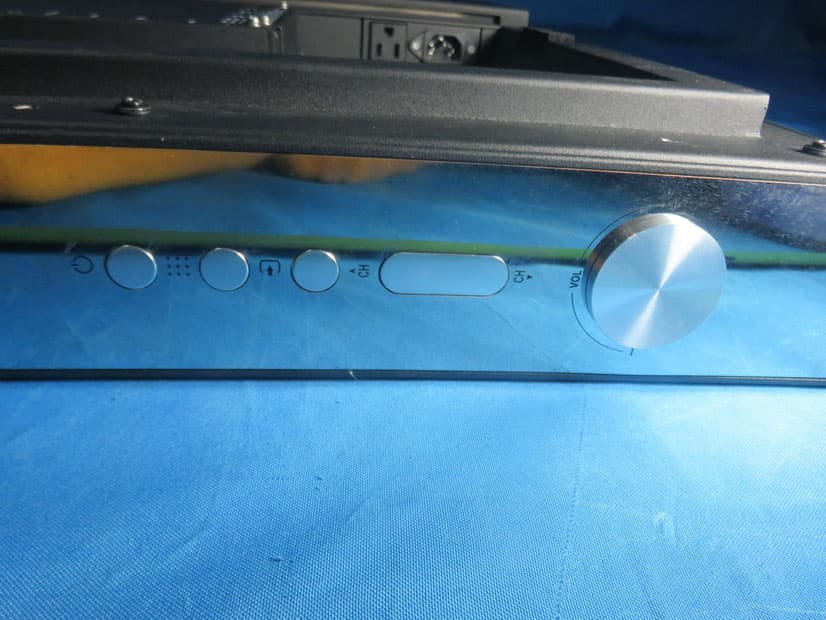
Click to zoom
Application Details
- Equipment Class
- DTS - Digital Transmission System
- Date of Grant
- Jun 27, 2021
- Application Purpose
- Original Equipment
- Date of Application
- Jun 24, 2021
- Equipment Note
- Ultra Bright LCD Display with LED Backlight
- Frequency Range
- 2402.00000000 - 2480.00000000
- Company
- Innolux Corporation
- Country
- Taiwan
Documents & Files
Document Text
Text extracted from the exhibit documents filed with the FCC. Open a document above to read the original.
Users Manual
WELCOME GUIDE Ultra Bright ™ UB4-50 UB4-65 UB4-85 WARRANTY REGISTRATION REGISTER FOR EXTRA BENEFITS Activate within 30 days of purchase: seura.com/activate 2 3 Specifications 50 INCH Model: UB4-50 65 INCH Model: UB4-65 85 INCH Model: UB4-85 GENERAL OPERATING TEMP.-40°F to 122°F IDEAL OPERATING TEMP. 32°F to 122°F NON-OPERATING TEMP. -40°F to 140°F OPERATING HUMIDITY 5%-90% Relative Humidity, Non-Condensing WATERPROOFIP55 Rating* VIDEO RESOLUTIONFull UHD Native 3840 x 2160 BRIGHTNESS1900 Nits CONTRAST RATIO5000:1 DOLBY DIGITAL COMPLIANT Yes (HDMI and Digital Audio Outs) HDR COMPATIBLEHDR-10 RESPONSE TIME8 ms VIEWING ANGLE178° Horizontal/Vertical DISPLAY POWER CONS. Standby: 3.5W Heating: 398W Normal: 361W Max Standby: 3.5W Heating: 682W Normal: 625W Max Standby: 3.5W Heating: 1096W Normal: 1018W Max INSTALLATION DIMENSIONS45.1” w x 26.2” h x 3.8” d58.2” w x 33.6” h x 3.8” d75.8” w x 43.5” h x 3.8” d TV WEIGHT65 lbs.90 lbs.140 lbs. VESA PATTERN400 x 400mm400 x 400mm600 x 400mm * IP Rating is an international standard that specifies the degree of protection against dust and water ingress. Séura Outdoor Displays are IP rated and designed to protect against rain, snow, ice, dust, and other outdoor elements. Manufactured under license from Dolby Laboratories. Dolby and the double-D symbol are trademarks of Dolby Laboratories. 4 This symbol is intended to alert the user to the presence of uninsulated “dangerous voltage” within the product’s enclosure that may be of sufficient magnitude to constitute a risk of electric shock to persons. This symbol is intended to alert the user to the presence of important operating and maintenance instructions in the literature accompanying the appliance. WARNING: READ ALL INSTRUCTIONS BEFORE ATTEMPTING TO INSTALL OR SERVICE THIS PRODUCT. Warnings: Do not handle or remove your outdoor display from the packaging until it is ready to be installed. To avoid damage to the outdoor display, only transport it in a vertical position. It is highly recommended that at least two (2) persons assist in the installation of the outdoor display. CAUTION RISK OF ELECTRIC SHOCK DO NOT OPEN CAUTION: TO REDUCE THE RISK OF ELECTRIC SHOCK DO NOT OPEN BACK PANEL, NO USER-SERVICEABLE PARTS INSIDE, REFER SERVICING TO QUALIFIED SERVICE PERSONNEL. Do not submerge Séura ® Outdoor Display in water: The Séura ® Outdoor Display will resist water exposure from normal rain, sprinklers, snow, etc.; however, it is not designed to be submerged in water. Do not wash with garden hose or pressure-wash: Séura ® Outdoor Display will resist water exposure from normal rain, sprinklers, snow etc.; however, it is not designed to withstand pressure washers, high-pressure water jets, projected snow from a blower, or hurricane-type weather. Do not let metal pieces or objects of any kind fall into the display. High voltage flows in the product, and inserting an object can cause electric shock and/or short internal parts. To prevent fire, never place any type of candle or flames on the top or near the display. To prevent fire or shock hazard, do not place the AC cord under the display or other heavy items. Power Lines An outside antenna system should not be located in the vicinity of overhead power lines or other electric light or power circuits, or where it can fall into such power lines or circuits. When installing an outside antenna system, extreme care should be taken to keep from touching such power lines or circuits as contact with them might be fatal. Accessories Do not use accessories not specifically recommended by the manufacturer. Use of improper attachments can result in accidents. 5 Ce symbole est destiné à alerter l’utilisateur de la présence d’une «tension dangereuse» non isolée à l’intérieur de l’enceinte du produit qui peut être d’une amplitude suffisante pour constituer un risque de choc électrique pour les personnes. Ce symbole est destiné à alerter l’utilisateur de la présence d’instructions importantes d’utilisation et de maintenance dans la documentation accompagnant l’appareil. AVERTISSEMENT: LIRE TOUTES LES INSTRUCTIONS AVANT D’INSTALLER OU SERVICE CE PRODUIT. Avertissements: Ne pas manipuler ou supprimer votre moniteur extérieure de l’emballage jusqu’ à ce qu’ il soit prêt à être installé. Pour éviter d’endommager la moniteur en plein air, seul le transporter dans une position verticale. Il est fortement recommandé qu’au moins deux (2) personnes aident à l’ installation de la moniteur en plein air. CAUTION RISQUE DE CHOC ELECTRIQUE. NE PAS OUVRIR. ATTENTION: POUR RÉDUIRE LE RISQUE DE CHOC ÉLECTRIQUE, NE RETIREZ PAS LE CAPOT (NI L’ARRIÈRE), AUCUNE PIÈCE RÉPARABLE PAR L’UTILISATEUR, RÉFÉREZ L’ENTRETIEN AU PERSONNEL DE SERVICE QUALIFIÉ. N’ immergez pas le Séura® Outdoor moniteur dans l’eau: le moniteur Séura® Outdoor résistera à l’exposition à l’eau causée par la pluie, les gicleurs, la neige, etc. Cependant, il n’est pas conçu pour être immergé dans l’eau. Ne lavez pas avec un tuyau d’arrosage ou avec un nettoyeur haute pression: Séura® Outdoor moniteur résistera à l’exposition à l’eau causée par la pluie, les sprinklers, la neige, etc. Cependant, il n’est pas conçu pour résister aux laveuses à pression, aux jets d’eau à haute pression, aux projections de neige d’un ventilateur ou aux intempéries de type ouragan. Ne laissez pas de morceaux de métal ou d’objets de toute sorte tomber dans la moniteur. Une tension élevée circule dans le produit et l’ insertion d’un objet peut provoquer un choc électrique et / ou un court-circuit des pièces internes. Pour éviter les incendies, ne placez jamais de bougies ni de flammes sur le dessus ou à proximité du moniteur. Pour éviter tout risque d’ incendie ou d’ électrocution, ne placez pas le cordon d’alimentation sous le moniteur ou d’autres objets lourds. Les lignes électriques Une antenne extérieure ne doit pas être située à proximité de lignes électriques aériennes ou d’autres circuits d’ éclairage ou de circuits électriques, ni à un endroit où ell…
Text truncated - open the document above for the full version.
External Photos
Report No.: 2103T148 Page 2 of 17 Report No.: 2103T148 Page 3 of 17 Report No.: 2103T148 Page 4 of 17
ID Label/Location Info
PRODUCT SPECIFICATION Version 1.0 18 Date: :: :23 Dec. 2020 The copyright belongs to InnoLux. Any unauthorized use is prohibited 6.4 RATING LABEL
Internal Photos
Report No.: 2103T148 Page 5 of 17 Antenna Report No.: 2103T148 Page 6 of 17 Report No.: 2103T148 Page 7 of 17 Report No.: 2103T148 Page 8 of 17 Report No.: 2103T148 Page 9 of 17 Report No.: 2103T148 Page 10 of 17 Report No.: 2103T148 Page 11 of 17 Report No.: 2103T148 Page 12 of 17 Report No.: 2103T148 Page 13 of 17 Report No.: 2103T148 Page 14 of 17 Report No.: 2103T148 Page 15 of 17 Report No.: 2103T148 Page 16 of 17 Report No.: 2103T148 Page 17 of 17
RF Exposure Info
Report No.: BTL-FCCP-3-2103T148 Page 1 of 4 FCC RF EXPOSURE REPORT FCC ID: 2AQPW-SB450 Project No. : 2103T148 Equipment : Ultra Bright LCD Display with LED Backlight Brand Name : Seura Test Model : UB4-50 Series Model : N/A Applicant : Innolux Corporation Address : No. 160, Kesyue Rd. Jhunan Science Park, Miaoli County, Taiwan 350 Manufacturer : Innolux Corporation Address : No. 160, Kesyue Rd. Jhunan Science Park, Miaoli County, Taiwan 350 Factory : Keewin Display (Suzhou) Co.,LTD Address : No. 17 Chengpu Rd,Suzhou Industrial Park,Jiangsu Date of Receipt : Mar. 29, 2021 Date of Test : Mar. 29, 2021 ~ May 11, 2021 Issued Date : Jun. 24, 2021 Report Version : R00 Test Sample : Engineering Sample No.: DG20210325161 Standard(s) : FCC Guidelines for Human Exposure IEEE C95.1 & FCC Part 2.1091 FCC Title 47 Part 2.1091, OET Bulletin 65 Supplement C The above equipment has been tested and found compliance with the requirement of the relative standards by BTL Inc. Prepared by : Nick Chen Approved by : Ethan Ma Add: No.3, Jinshagang 1st Road, Shixia, Dalang Town,Dongguan, Guangdong, China. Tel: +86-769-8318-3000 Web: www.newbtl.com Report No.: BTL-FCCP-3-2103T148 Page 2 of 4 REPORT ISSUED HISTORY Report Version Description Issued Date R00 Original Issue Jun. 24, 2021 Report No.: BTL-FCCP-3-2103T148 Page 3 of 4 1. TEST FACILITY The test facilities used to collect the test data in this report is at the location of No.3,Jinshagang 1st Road, Shixia, Dalang Town, Dongguan, Guangdong, China. BTL's Test Firm Registration Number for FCC: 357015 BTL's Designation Number for FCC: CN1240 2. MPE CALCULATION METHOD Calculation Method of RF Safety Distance: where: S = power density P = power input to the antenna G = power gain of the antenna in the direction of interest relative to an isotropic radiator R = distance to the center of radiation of the antenna Table for Filed Antenna: Ant. Brand Model Name Antenna Type Connector Gain(dBi) 1 SHENZHEN ZHONGTIAN XUN Communication Technology Shares Co., Ltd. 61005-00244 Internal N/A 2.99 Note: The antenna gain is provided by the manufacturer. Report No.: BTL-FCCP-3-2103T148 Page 4 of 4 3. TEST RESULTS For BT: Antenna Gain (dBi) Antenna Gain (numeric) Max. Peak Output Power (dBm) Max. Peak Output Power (mW) Power Density (S) (mW/cm 2 ) Limit of Power Density (S) (mW/cm 2 ) Test Result 2.99 1.9907 9.09 8.1096 0.00321 1 Complies For LE: Antenna Gain (dBi) Antenna Gain (numeric) Max. Peak Output Power (dBm) Max. Peak Output Power (mW) Power Density (S) (mW/cm 2 ) Limit of Power Density (S) (mW/cm 2 ) Test Result 2.99 1.9907 1.81 1.5171 0.00060 1 Complies Note: The calculated distance is 20 cm. Output power including tune up tolerance. End of Test Report
Test Report
Report No.: BTL-FCCP-2-2103T148 Page 1 of 76 FCC Radio Test Report FCC ID: 2AQPW-SB450 This report concerns: Original Grant Project No. : 2103T148 Equipment : Ultra Bright LCD Display with LED Backlight Brand Name : Seura Test Model : UB4-50 Series Model : N/A Applicant : Innolux Corporation Address : No. 160, Kesyue Rd. Jhunan Science Park, Miaoli County, Taiwan 350 Manufacturer : Innolux Corporation Address : No. 160, Kesyue Rd. Jhunan Science Park, Miaoli County, Taiwan 350 Factory : Keewin Display (Suzhou) Co.,LTD Address : No. 17 Chengpu Rd,Suzhou Industrial Park,Jiangsu Date of Receipt : Mar. 29, 2021 Date of Test : Mar. 29, 2021 ~ May 11, 2021 Issued Date : Jun. 21, 2021 Report Version : R01 Test Sample : Engineering Sample No.: DG20210325161 Standard(s) : FCC CFR Title 47, Part 15, Subpart C FCC KDB 558074 D01 15.247 Meas Guidance v05r02 ANSI C63.10-2013 T he above equipment has been tested and found compliance with the requirement of the relative standards by BTL Inc. Prepared by : Nick Chen Approved by : Ethan Ma Add: No.3, Jinshagang 1st Road, Shixia, Dalang Town,Dongguan, Guangdong, China. Te l : +86-769-8318-3000 Web: www.newbtl.com Report No.: BTL-FCCP-2-2103T148 Page 2 of 76 Declaration BTL represents to the client that testing is done in accordance with standard procedures as applicable and that test instruments used has been calibrated with standards traceable to international standard(s) and/or national standard(s). BTL's reports apply only to the specific samples tested under conditions. It is manufacture’s responsibility to ensure that additional production units of this model are manufactured with the identical electrical and mechanical components. BTL shall have no liability for any declarations, inferences or generalizations drawn by the client or others from BTL issued reports. The report must not be used by the client to claim product certification, approval, or endorsement by NVLAP, NIST, A2LA, or any agency of the U.S. Government. This report is the confidential property of the client. As a mutual protection to the clients, the public and ourselves, the test report shall not be reproduced, except in full, without our written approval. BTL’s laboratory quality assurance procedures are in compliance with the ISO/IEC 17025 requirements, and accredited by the conformity assessment authorities listed in this test report. BTL is not responsible for the sampling stage, so the results only apply to the sample as received. The information, data and test plan are provided by manufacturer which may affect the validity of results, so it is manufacturer’s responsibility to ensure that the apparatus meets the essential requirements of applied standards and in all the possible configurations as representative of its intended use. Limitation For the use of the authority's logo is limited unless the Test Standard(s)/Scope(s)/Item(s) mentioned in this test report is (are) included in the conformity assessment authorities acceptance respective. Please note that the measurement uncertainty is provided for informational purpose only and are not use in determining the Pass/Fail results. Report No.: BTL-FCCP-2-2103T148 Page 3 of 76 Table of Contents Page REPORT ISSUED HISTORY 6 1 . SUMMARY OF TEST RESULTS 7 1.1 TEST FACILITY 8 1.2 MEASUREMENT UNCERTAINTY 8 1.3 TEST ENVIRONMENT CONDITIONS 9 2 . GENERAL INFORMATION 10 2.1 GENERAL DESCRIPTION OF EUT 10 2.2 DESCRIPTION OF TEST MODES 11 2.3 PARAMETERS OF TEST SOFTWARE 12 2.4 BLOCK DIAGRAM SHOWING THE CONFIGURATION OF SYSTEM TESTED 13 2.5 SUPPORT UNITS 13 3 . AC POWER LINE CONDUCTED EMISSIONS 14 3.1 LIMIT 14 3.2 TEST PROCEDURE 14 3.3 DEVIATION FROM TEST STANDARD 14 3.4 TEST SETUP 15 3.5 EUT OPERATING CONDITIONS 15 3.6 TEST RESULTS 15 4 . RADIATED EMISSIONS 16 4.1 LIMIT 16 4.2 TEST PROCEDURE 17 4.3 DEVIATION FROM TEST STANDARD 18 4.4 TEST SETUP 18 4.5 EUT OPERATING CONDITIONS 19 4.6 TEST RESULT - 9 KHZ TO 30 MHZ 19 4.7 TEST RESULT - 30 MHZ TO 1000 MHZ 19 4.8 TEST RESULT - ABOVE 1000 MHZ 19 5 . BANDWIDTH 20 5.1 LIMIT 20 5.2 TEST PROCEDURE 20 5.3 DEVIATION FROM STANDARD 20 5.4 TEST SETUP 20 Report No.: BTL-FCCP-2-2103T148 Page 4 of 76 Table of Contents Page 5.5 EUT OPERATION CONDITIONS 20 5.6 TEST RESULTS 20 6 . MAXIMUM OUTPUT POWER 21 6.1 LIMIT 21 6.2 TEST PROCEDURE 21 6.3 DEVIATION FROM STANDARD 21 6.4 TEST SETUP 21 6.5 EUT OPERATION CONDITIONS 21 6.6 TEST RESULTS 21 7 . CONDUCTED SPURIOUS EMISSION 22 7.1 LIMIT 22 7.2 TEST PROCEDURE 22 7.3 DEVIATION FROM STANDARD 22 7.4 TEST SETUP 22 7.5 EUT OPERATION CONDITIONS 22 7.6 TEST RESULTS 22 8 . POWER SPECTRAL DENSITY 23 8.1 LIMIT 23 8.2 TEST PROCEDURE 23 8.3 DEVIATION FROM STANDARD 23 8.4 TEST SETUP 23 8.5 EUT OPERATION CONDITIONS 23 8.6 TEST RESULTS 23 9 . MEASUREMENT INSTRUMENTS LIST 24 10 . EUT TEST PHOTO 26 APPENDIX A - AC POWER LINE CONDUCTED EMISSIONS 31 APPENDIX B - RADIATED EMISSION - 9 KHZ TO 30 MHZ 34 APPENDIX C - RADIATED EMISSION - 30 MHZ TO 1000 MHZ 39 APPENDIX D - RADIATED EMISSION - ABOVE 1000 MHZ 42 APPENDIX E - BANDWIDTH 67 APPENDIX F - MAXIMUM OUTPUT POWER 70 Report No.: BTL-FCCP-2-2103T148 Page 5 of 76 Table of Contents Page APPENDIX G - CONDUCTED SPURIOUS EMISSION 72 APPENDIX H - POWER SPECTRAL DENSITY 75 Report No.: BTL-FCCP-2-2103T148 Page 6 of 76 REPORT ISSUED HISTORY Report Version Description Issued Date R00 Original Issue. Jun. 18, 2021 R01 Changed the product name. Jun. 21, 2021 Report No.: BTL-FCCP-2-2103T148 Page 7 of 76 1. SUMMARY OF TEST RESULTS Test procedures according to the technical standard(s): FCC CFR Title 47, Part 15, Subpart C Standard(s) Section Test Item Test Result Judgment Remark 15.207 AC Power Line Conducted Emissions APPENDIX A PASS ------ 15.247(d) 15.205(a) 15.209(a) Radiated Emissions APPENDIX B APPENDIX C APPENDIX D PASS ------ 15.247(a)(2) Bandwidth APPENDIX E PASS ------ 15.247(b)(3) Maximum Output Power APPENDIX F PASS ------ 15.247(d) Conducted Spurious Emission APPENDIX G PASS ------ 15.247(e) Power Spectral Density APPENDIX H PASS ------ 1…
Text truncated - open the document above for the full version.
Test Setup Photos
Report No.: BTL-FCCP-1-2103T148 Page 29 of 91 12. EUT TEST PHOTO AC Power Line Conducted Emissions Test Photos Report No.: BTL-FCCP-1-2103T148 Page 30 of 91 Radiated Emissions Test Photos 9 kHz to 30 MHz Report No.: BTL-FCCP-1-2103T148 Page 31 of 91 Radiated Emissions Test Photos 30 MHz to 1000 MHz Report No.: BTL-FCCP-1-2103T148 Page 32 of 91 Radiated Emissions Test Photos Above 1 GHz Report No.: BTL-FCCP-1-2103T148 Page 33 of 91 Conducted Test Photos
Contact Information
Applicant
Janice Chao(Engineer)
Technical Contact
Non-Technical Contact
BTL Inc.Rose Liu
[email protected]86-769-83183000
Test Firm
BTL Inc.Sophia Huang
[email protected]+86-769-83183000
Technical Specifications
| # | Rule Parts | Frequency Range | Power Output |
|---|---|---|---|
| 1 | 15C | 2.40 GHz - 2.48 GHz | 1.50 mW |
Other Applications from Innolux Corporation
2AQPW-DD313IA-01A
Jan 23, 2023Automotive Rear Seat Entertainment LCD display mounted on the ceiling
Equipment Class
DSS - Part 15 Spread Spectrum Transmitter
2AQPW-SB465
Jul 11, 2021Ultra Bright LCD Display with LED Backlight
Equipment Class
DTS - Digital Transmission System