2AQURZW39M-V8Z-Wave Dimmer Plug
NIE-TECH CO., LTD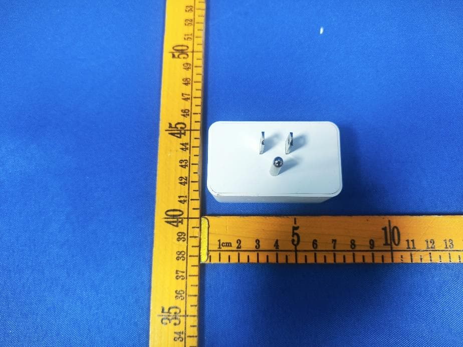
Click to zoom
Application Details
- Equipment Class
- DXX - Part 15 Low Power Communication Device Transmitter
- Date of Grant
- Dec 31, 2023
- Application Purpose
- Original Equipment
- Date of Application
- Dec 31, 2023
- Equipment Note
- Z-Wave Dimmer Plug
- Frequency Range
- 908.40000000 - 916.00000000
- Company
- NIE-TECH CO., LTD
- Country
- China
Documents & Files
Document Text
Text extracted from the exhibit documents filed with the FCC. Open a document above to read the original.
Users Manual
Please contact us if you have any questions: [email protected] www.newonetree.com Indoor use in dry location 1: Press the button 5 times quickly, the LED indicator flashes slowly to enter the setting “Min brightness” mode. The lamp will adjusts to the min brightness automatically. brightness” mode. The lamp will adjusts to the max brightness automatically. the max brightness. The LED indicator will flashes 3 times. the min brightness. The LED indicator will flashes 3 times. 2: Hold the button to adjust the brightness of the bulb, select the appropriate brightness to set 3: Press the button 5 times quickly to confirm it (the min brightness setting is completed). 1: Press the button 10 times quickly, the LED indicator flashes slowly to enter the setting “Max 2: Hold the button to adjust the brightness of the bulb, select the appropriate brightness to set 3: Press the button 10 times quickly to confirm it (the max brightness setting is completed). Remark: If the setting is not confirmed at Step 3, the setting mode will be exited after 10S. 1. Z-Wave on / off + dimmer control. 2. Grounded 3-wire power connection for safety. 3. Remember and restore on/off status after power failure. 4. Built-in Z-Wave Plus signal repeater to extend network range 5. S2 security and 800 Z-Wave chip for reliable wireless communication. 6. Work with all certificated Z-Wave controllers. 7. Support Long Range. Min brightness level setting( Refer to Parameter 11) Max brightness level setting( Refer to Parameter 12) Features: devices from other manufacturers and/or other applications. All non-battery operated nodes This product can be included and operated in any Z-Wave network with other Z-Wave certified within the network will act as repeaters regardless of vendor to increase the reliability of the network. This Device supports Lifeline (association group 1) supporting 1 node for lifeline communication. Group 1 must be assigned the Node ID of the primary controller where unsolicited notifications will be sent. The Z-Wave controller should set this association automatically after inclusion. Lifeline association only supports the “Device Reset Locally” function. This parameter can access you to set a timer to make the switch turn off automatically after the switch turns on.The numberentered as value (LED flashes 3 times when the configuration parameter changed.) --- Parameter =4, Size=4Value: 0– 65535(minutes); Value=0(default) disable Auto Turn-Off Timer corresponds to number of minutes. Operation: Set up on the hub. Z-Wave Dimmer Plug(800S) • MP31ZD • Specification Input: 125VAC 60Hz Frequency: 908.42 MHz Dimmable CFL/LED Loading: 200W Incandescent 100W Program button Press 1x: Manually Reset: Press the button twice quickly then hold a 3rd press for 10 seconds LED indicator Blue: Light status indicator Blue: ADD / Inclusion Purple: Remove / Exclusion Red: Network Failure Z-WAVE INTEROPERABILITY Adding Device To Z-Wave Network for QR CODE Scan here for SmartStar inclusion Note: DSK Code can be found on the packaging box. Do not remove or damage them. Z-Wave Network Configuration Adding Device To Z-Wave Network Again: If you have issues with pairing / including, please move the device as close as possible to the hub and try again--you can move to your final location when completed. Note:If the manual button doesn't light up after pressing 3 times, please reset the device: press the button twice quickly then hold a 3rd press for 10 seconds. (2)The flashing purple light means the device is already paired and also in exclusion mode. If adding fails, please do a z-wave exclusion on your z-wave controller and re-add it. 2. Once the controller is ready to add your device, press the Manual/ Program button on the smart plug 3 times quickly. The blue LED will flash quickly. 1. Follow the instructions for your Z-Wave certified controller to add a device to the Z-Wave network. Now, you have completed control to turn your device ON / OFF according to groups, schedules and interactive automation programmed by your controller. If your Z-Wave certified controller features remote access, you can control your device from your mobile devices. 1. Follow the instructions for your Z-Wave certified controller to remove a device from the Z-Wave network. 2. Once the controller is ready to remove your device, press the manual / program button on the smart plug 3 times quickly. Manual: Press the button twice quickly then hold a 3rd press for 10 seconds. Host reset: Remove it from hub, the device will be restore to factory default. •The device is compatible with smartstart. SmartStart enabled products can be added into a Z-Wave network by scanning the Z-Wave QR Code found on the top of the outlet or the back of the box with a controller providing SmartStart inclusion. No furthe action is required and the SmartStart product will be added automaticaly within 10 minutes of being switched on and in the network vicinity. •Note:Z- Wave Long Range device can only support be included via SmartStart. Extract the DSK from end device and paste it into the DSK Value in PC Controller, make sure the Long Range' option is ticked. Association Group 1: Z-Wave Plus Lifeline Association Group 2: Send Basic Set ON / Off Group 1 supports 1 node ID,Group 2 Supports maximum of 5 node ID’s To Remove The Device To Return The Device To Factory Defaults Add QR Code For LR Association Group Our Products warrant this product to be free from manufacturing defects for a period of one year from the original date of consumer purchase. This warranty is limited to the repair or replacement of this product only and does not extend to consequential or incidental damage to other products that may be used with this product. This warranty is in lieu of all other warranti- es, expressed or implied. Some states do not allow limitations on how long an implied warranty lasts or permit the exclusion or limitation of incidental or consequential damage, so the above limitations may not a…
Text truncated - open the document above for the full version.
Attestation Statements
{NIE-TECH Co., Ltd} { Jinlian commercial center 9001, Jinxiu road No.2, Changan Town,Dongguan City, GuangDongProv., CHINA } Federal Communications Commission Authorization and Evaluation Division Equipment Authorization Branch 7435 Oakland Mills Road Columbia, MD 21046 {2023-12-27} U.S. Agent Designation { NIE-TECH Co., Ltd} acknowledges their consent for the following contact located in the United States to act as their agent for service of process for the equipment for which authorization is sought (FCC ID: 2AQURZW39M-V8): Name and company of U.S. agent: { Jasco Products Company LLC } Physical U.S. address of agent: {10 e memorial road Office oklahoma city OK 73114} FRN of U.S. agent: {0017309360} Email address of U.S. agent: {[email protected]} { Jasco Products Company LLC } acknowledges their obligation to accept service of process on behalf of {NIE- TECH Co., Ltd}. { NIE-TECH Co., Ltd} with the FRN [{0027755610}] accepts its obligation to maintain an agent for service of process in the United States for no less than one year after either the grantee has permanently terminated all marketing and importation of the applicable equipment within the U.S., or the conclusion of any Commission-related administrative or judicial proceeding involving the equipment, whichever is later. By signing this form, we confirm the above and that we are aware of the application requirements listed under § 2.911(d)(7). The information provided in this letter is based on the referenced rule parts of Title 47 of the CFR as well as KDB 986446 D01. An expiration date for this letter does not exist. In case the U.S. agent changes, the grantee is obligated to notify the FCC within 30 days via the granting TCB. Sincerely, { } Signature { jianghai} { Nie } { Manager } {NIE-TECH Co., Ltd} {} Signature {Mark Simpkins} {Manager} {Jasco Products Company LLC} 48_[mo del] US_Agent_2.911(d)(7) - U, V0 5
External Photos
FCC ID: 2AQURZW39M-V8 FCC ID: 2AQURZW39M-V8 FCC ID: 2AQURZW39M-V8
ID Label/Location Info
Model: MP31ZD (ZW39M) Input: 125VAC 60Hz Frequency: 908.42 MHz Date: Made in China FCC ID: 2AQURZW39M-V8 VER: 8.0 For indoor use 100W Dimmable CFL/LED Loading: 200W Incandescent Conforms to UL Cert. to CSA Std. E60730-1:2015 Std. 60730-1:2016 MP31ZD(ZW39M) Z-Wave Dimmer Smart Plug(800S)
Internal Photos
FCC ID: 2AQURZW39M-V8 FCC ID: 2AQURZW39M-V8 FCC ID: 2AQURZW39M-V8 FCC ID: 2AQURZW39M-V8 ANT FCC ID: 2AQURZW39M-V8
RF Exposure Info
Page 1 of 3 RF EXPOSURE EVALUATION FCC ID: QOBZWN6310 Product Name : Z-Wave Dimmer Plug Model Name : ZW39M, MP31ZD,N4012 Operating frequency : 908.40MHz 908.42MHz 916.00MHz 912 MHz 920 MHz Type of Modulation : 2FSK for 908.40MHz 2FSK for 908.42MHz 2GFSK for 916.00MHz DSSS OQPSK LR for 912 MHz and 920 MHz Antenna Type : PCB Antenna Antenna Gain : -6.16dBi Power supply : Input: AC 125V/60Hz Output: 125V 200W 60Hz Hardware Version : V1.3 Software Version : V1 Page 2 of 3 Standard Requirement According to § 15.247(i) and § 1.1307b(1), systems operating under the provisions of this section shall be operated in a manner that ensures that the public is not exposed to radio frequency energy levels in excess of the Commission’s guidelines. See KDB 447498 D01 General RF Exposure Guidance v06, section 4. 3. 1. The 1-g and 10-g SAR test exclusion thresholds for 100MHz to 6GHz at test separation distances ≤ 50mm are determined by: [ (max. power of channel, including tune-up tolerance, mW)/(min. test separation distance, mm)]*[ √f(GHz)] ≤3.0 for 1-g SAR and ≤7.5 for 10-g SAR extremity SAR, where f(GHz) is the RF channel transmit frequency in GHz Power and distance are rounded to the nearest mW and mm before calculation The result is rounded to one decimal place for comparison. The test exclusions are applicable only when the minimum test separation distance is ≤ 50mm and for transmission frequencies between 100MHz and 6GHz. When the minimum test separation distance is <5mm, a distance of 5mm is applied to determine SAR test exclusion. Routine SAR evaluation refers to that specifically required by § 2.1093, using measurements or computer simulation. When routine SAR evaluation is not required, portable transmitters with output power greater than the applicable low threshold require SAR evaluation to quality for TCB approval. E (V/m) = d G P 30 Power Density: Pd (W/m²) = 377 2 E E = Electric field (V/m) P = Peak RF output power (W) G = EUT Antenna numeric gain (numeric) d = Separation distance between radiator and human body (m) The formula can be changed to Pd = 2 377 30 d GP θφ From the peak EUT RF output power, the minimum mobile separation distance, d=0.2m, as well as the gain of the used antenna, the RF power density can be obtained Page 3 of 3 RF Output power Freq. (MHz) Field strength(max)(dBuV/m) EIRP (max) (dBm) 908.40 90.11 -5.09 908.42 90.21 -4.99 916.00 89.59 -5.61 Note: EIRP=E-104.8+20logD, Where E is the electric field strength in dBμV/m. EIRP is the equivalent isotropically radiated power in dBm. d is the specified measurement distance in m. where D=3, EIRP=E-95.2. Channel (MHz) Maximum output power (dBm) Tune up tolerance (dBm) Max Tune Up Power (mW) Distance (mm) Calculation results Limit Result 912MHz -0.380 0.00 ± 1 1.000000 5 0.190997 3 Pass 920MH -0.611 -0.50 ± 1 0.891251 5 0.170972 3 Pass 908.40MH -5.09 -5.00 ± 1 0.316228 5 0.060279 3 Pass 908.42MH -4.99 -4.50±1 0.354813 5 0.067635 3 Pass 916.00MH -5.61 -5.50±1 0.281838 5 0.053948 3 Pass According to KDB 447498, no stand-alone required for the antenna, and no simultaneous SAR measurement is required. Signature Manager Simon Pu Date: 2023-12-26
Test Report
ReportNo.:RFI-LAB-RF-202306-FF05-3 QP030-E41 Page1of10 TestingReport CustomerName:NIE-TECHCo.,Ltd ProductName:ZW800_V8.42 SampleModel:ZW800_V8.42ANT ReferenceStandard:GB/T9410-2008;ANSI/IEEEStd149-1979 IssueDate:2023.6.12 Engineer:Date: Auditor:Date: Approver:Date: ReportNo.:RFI-LAB-RF-202306-FF05-3 QP030-E41 Page2of10 Version VersionNo.DateDescriptionFormulateApproval A02023.6.12Forthefirsttime,formulateZkrisEason Contents 1.GeneralInformation.........................................................................................................................3 1.1Generalinformationoftestinginstitutions...........................................................................3 1.2Testingprinciple...................................................................................................................3 1.3Testequipment......................................................................................................................4 1.4Testenvironment...................................................................................................................4 1.5Statement..............................................................................................................................4 2.SampleInformation.........................................................................................................................5 2.1Clientinformation.................................................................................................................5 2.2DescriptionofEUT(S)..........................................................................................................5 2.3EUTappearance....................................................................................................................6 2.4EUTsetupphotooffreespaceOTAtesting.........................................................................6 3.TestResults.....................................................................................................................................7 3.1Teststandard.........................................................................................................................7 3.2Testuncertainty.....................................................................................................................7 3.3Testdata................................................................................................................................8 3.3.1VSWRparameters.....................................................................................................8 3.3.2VSWRdata................................................................................................................8 3.3.3Typicalfreespaceefficiencyandgain......................................................................8 3.3.4Typicalfreespaceradiationpattern...........................................................................9 (Thefollowingisblank)..............................................................................................................10 ReportNo.:RFI-LAB-RF-202306-FF05-3 QP030-E41 Page3of10 1.GeneralInformation 1.1Generalinformationoftestinginstitutions Name ShenzhenRFI-LABCommunicationTechnologyCo.,Ltd. Address 10/FA,LingyunBld,LiufangRd,BaoanDistrict,SZ Tel 13682621346 E-mail [email protected] Equipment AlltheequipmentusedinthereportisfixedinZoneB,WestSideof1/F,Building1, TingweiIndustrialPark,No.6LiufangRoad,Bao'anDistrict,Shenzhen 1.2Testingprinciple ReportNo.:RFI-LAB-RF-202306-FF05-3 QP030-E41 Page4of10 1.3Testequipment EquipmentModelNo.SerialNo.Manufacturer Calibration date Next calibration date OTATest System RayZone-5000 RFI-LAB-RF -D00 GTS2023.3.142025.3.13 Network Analyzer E5071C RFI-LAB-RF -D01 KEYSIGHT2023.5.112024.5.10 Network Analyzer E5071C RFI-LAB-RF -C02 KEYSIGHT2023.5.112024.5.10 1.4Testenvironment Temperature 24.2°C Humidity 59%RH Pressure 100.15kPa 1.5Statement (1)Thetestresultsinthereportareonlyapplicabletothetestedsamplesandthetestedsamples workundertheenvironmentdescribedinthereport. (2)OnlyShenzhenRFI-LABCommunicationTechnologyCo.,Ltd.havetherighttomodifythe report,andthemodificationinformationshallbeannotatedintherevisionform. (3)Anyobjectiontothisreportshallberaisedwithin30daysafterformalconfirmationofthe report. (4)Thisreportisinvalidifthereisanyevidencethatthesampleinformationprovidedisfalsified. (5)Thereportisinvalidwithoutthesignatureoftheauditorandapprover. ReportNo.:RFI-LAB-RF-202306-FF05-3 QP030-E41 Page5of10 2.SampleInformation 2.1Clientinformation Name NIE-TECHCo.,Ltd Address / Contacts / Tel / E-mail / Manufacturer / 2.2DescriptionofEUT(S) ProductName ZW800_V8.42 SampleModel ZW800_V8.42ANT AntennaSize / SerialNo. / AntennaType PCBAntenna TestItem VSWR;Antennagain;Efficiency;Radiationpattern FrequencyRange 902-928MHz ReceivedDate 2023.6.08 TestDate 2023.6.09 Remark ThelengthoftheRFcableis50mm ReportNo.:RFI-LAB-RF-202306-FF05-3 QP030-E41 Page6of10 2.3EUTappearance 2.4EUTsetupphotooffreespaceOTAtesting Planform Frontview ReportNo.:RFI-LAB-RF-202306-FF05-3 QP030-E41 Page7of10 3.TestResults 3.1Teststandard NameParameterMethodStandardno. Mobile communication antenna Antennagain Genericspecification forantennasusedinthe mobilecommunications GB/T 9410-2008 Radiationpattern VSWR Antenna Radiationefficiency IEEEStandardTest ProceduresforAntennas ANSI/IEEEStd 149-1979 Gainanddirectivity 3.2Testuncertainty TheuncertaintywascalculatedonthebasisoftheGUMpublishedbyISO,usingthe inclusionfactorofK=2andthe95%confidenceleveltoexpresstheextended uncertainty. ItemUncertainty VSWR±0.3 Antennagain±0.72dB Radiationefficiency±0.72dB ReportNo.:RFI-LAB-RF-202306-FF05-3 QP030-E41 Page8of10 3.3Testdata 3.3.1VSWRparameters 3.3.2VSWRdata 3.3.3Typicalfreespaceefficiencyandgain Frequency/MHz 902915928 VSWR 6.44816.50926.5622 Frequency/MHz 902904906908910912914916918920922924926928 PeakGain/dBi -7.64-7.43-7.29-7.16-7.05-6.91-6.77-6.61-6.48-6.36-6.26-6.21-6.21-6.16 Efficiency/% 6.046.196.286.376.526.696.897.067.257…
Text truncated - open the document above for the full version.
Test Report
FCC TEST REPORT FCC ID: 2AQURZW39M-V8 Product Name : Z-Wave Dimmer Plug Model Name : ZW39M,MP31ZD,N4012 Brand Name : Ministon Report No. : PTC23120112102E-FC01 Prepared for NIE-TECH Co., Ltd Jinlian commercial center 9001, Jinxiu road No.2, Changan Town,Dongguan City, GuangDongProv., CHINA Prepared by Precise Testing & Certification Co., Ltd. Building 1, No. 6, Tongxin Road, Dongcheng Street, Dongguan, Guangdong, China Report No.: PTC23120112102E-FC01 Page 2 of 38 1 TEST RESULT CERTIFICATION Applicant’s name : NIE-TECH Co., Ltd Address : Jinlian commercial center 9001, Jinxiu road No.2, Changan Town,Dongguan City, GuangDongProv., CHINA Manufacture's name : NIE-TECH Co., Ltd Address : Jinlian commercial center 9001, Jinxiu road No.2, Changan Town,Dongguan City, GuangDongProv., CHINA Product name : Z-Wave Dimmer Plug Model name : ZW39M,MP31ZD,N4012 Standards : FCC Part15 Subpart C, Paragraph 15.249 Test procedure : ANSI C63.10: 2013 Test Date : Dec. 06, 2023 to Dec. 26, 2023 Date of Issue : Dec. 26, 2023 Test Result : Pass This device described above has been tested by PTC, and the test results show that the equipment under test (EUT) is in compliance with the FCC requirements. And it is applicable only to the tested sample identified in the report. This report shall not be reproduced except in full, without the written approval of PTC, this document may be altered or revised by PTC, personal only, and shall be noted in the revision of the document. Test Engineer: Jack zhou / Engineer Technical Manager: Simon Pu / Manager Report No.: PTC23120112102E-FC01 Page 3 of 38 Contents Page 1 TEST RESULT CERTIFICATION .............................................................................................................................. 2 2 TEST SUMMARY ......................................................................................................................................................... 4 3 TEST FACILITY ............................................................................................................................................................ 5 4 GENERAL INFORMATION ........................................................................................................................................ 6 4.1 GENERAL DESCRIPTION OF E.U.T. .................................................................................................................... 6 4.2 TEST MODE ........................................................................................................................................................ 7 4.3 LIST OF CHANNELS ............................................................................................................................................. 8 5 EQUIPMENT DURING TEST ..................................................................................................................................... 9 5.1 EQUIPMENTS LIST............................................................................................................................................... 9 5.2 MEASUREMENT UNCERTAINTY ......................................................................................................................... 11 5.3 DESCRIPTION OF SUPPORT UNITS ................................................................................................................... 12 6 TEST STANDARD AND LIMIT ............................................................................................................................... 13 6.1. TEST SETUP .................................................................................................................................................... 13 6.2. TEST PROCEDURE ........................................................................................................................................... 13 6.3. TEST DATA ...................................................................................................................................................... 14 7 . RADIATED EMISSION AND BAND EDGE ......................................................................................................... 16 7.1. TEST STANDARD AND LIMIT ............................................................................................................................ 16 7.2. TEST SETUP .................................................................................................................................................... 17 7.3. TEST PROCEDURE ........................................................................................................................................... 18 7.4. TEST DATA ...................................................................................................................................................... 19 8. 20DB BANDWIDTH TEST ....................................................................................................................................... 22 8.1. TEST STANDARD AND LIMIT ............................................................................................................................ 26 8.2. TEST SETUP .................................................................................................................................................... 26 8.3. TEST PROCEDURE ........................................................................................................................................... 26 8.4. TEST DATA ...................................................................................................................................................... 26 9. ANTENNA REQUIREMENT .................................................................................................................................... 27 9.1. TEST STANDARD AND REQUIREMENT ............................................................................................................. 28 9.2. ANTENNA CONNECTED CONST…
Text truncated - open the document above for the full version.
Test Setup Photos
FCC ID: 2AQURZW39M-V8 Conducted Emissions Radiated Spurious Emissions From 30MHz-1000MHz FCC ID: 2AQURZW39M-V8 Test frequency from Above 1GHz
Contact Information
Applicant
Jianghai Nie(Manager)
Test Firm
Precise Testing & Certification Co., LTD.Chris Du
[email protected]+86-769-38808222
Technical Specifications
| # | Rule Parts | Frequency Range | Power Output |
|---|---|---|---|
| 1 | 15C | 908.4 MHz - 916 MHz | - |
Other Applications from NIE-TECH CO., LTD
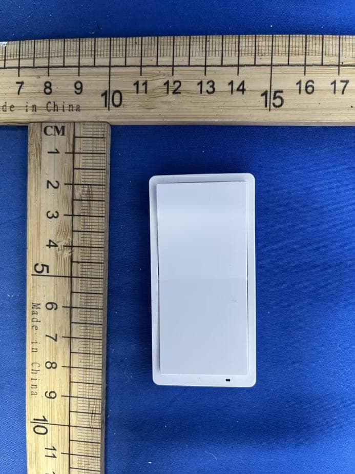
2AQUR-RF922
Jun 10, 20262 Button Remote ON/ON
Equipment Class
DSC - Part 15 Security/Remote Control Transmitter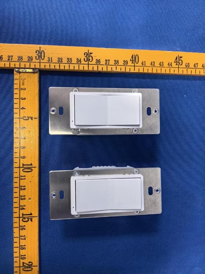
2AQUR-ZW305Z
Mar 03, 2026ON/OFF SWITCH 800
Equipment Class
DXX - Part 15 Low Power Communication Device Transmitter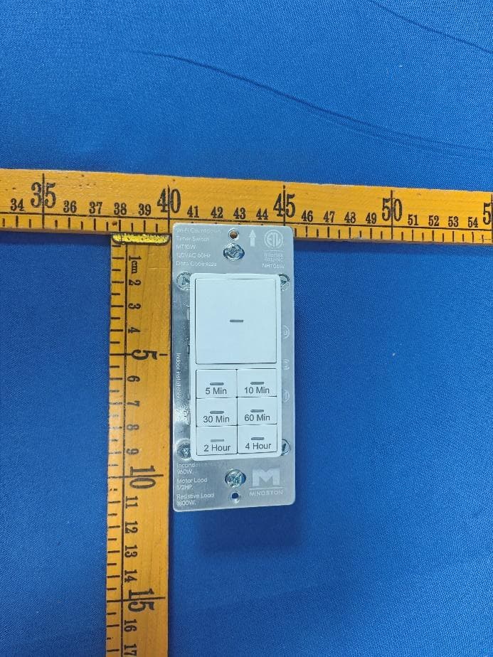
2AQURNHT06W
Jun 26, 2024Wi-Fi Countdown Timer Switch
Equipment Class
DTS - Digital Transmission System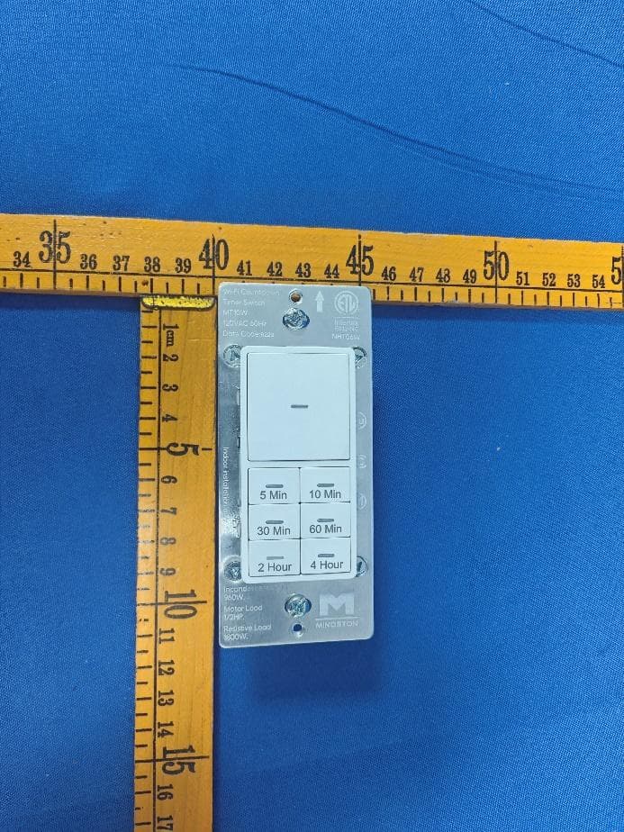
2AQURNHTO6W
Jun 26, 2024Wi-Fi Countdown Timer Switch
Equipment Class
DTS - Digital Transmission System
2AQURZW37MU
Mar 08, 2024Z-Wave Mini Smart Plug (800S)
Equipment Class
DXX - Part 15 Low Power Communication Device Transmitter