2AQVB-DN2458G2.4&5.8GHz HD Wireless Link
Taisync Technology Inc.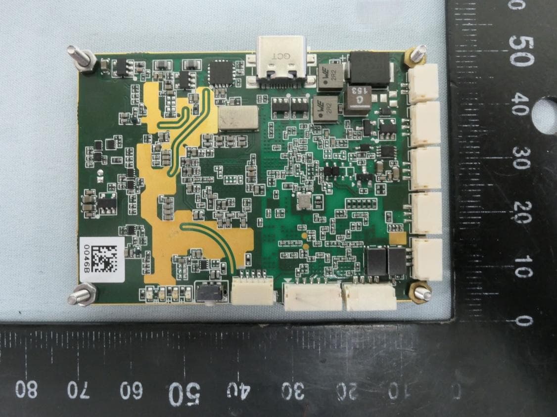
Click to zoom
Application Details
- Equipment Class
- DTS - Digital Transmission System
- Date of Grant
- Dec 15, 2025
- Application Purpose
- Original Equipment
- Equipment Note
- 2.4&5.8GHz HD Wireless Link
- Frequency Range
- 2412.00000000 - 2470.00000000
- Company
- Taisync Technology Inc.
- Country
- United States
Documents & Files
Document Text
Text extracted from the exhibit documents filed with the FCC. Open a document above to read the original.
Users Manual
Viulinx Dual-band Quick Start www.taisync.com Contents 1. Package Contents ....................................................................................................... 1 2. Introduction ................................................................................................................ 2 2.1. Air Unit Ports ................................................................................................... 2 2.2. Air Unit LEDs & Button .................................................................................. 3 2.3. Ground Unit Ports ............................................................................................ 3 2.4. Ground Unit LEDs & Button ........................................................................... 4 2.5. Setting up Air Unit ........................................................................................... 5 2.6. Setting up Ground Unit .................................................................................... 5 3. Web-page Management .............................................................................................. 7 3.1. Manage Air Unit .............................................................................................. 7 3.2. Manage Ground Unit ..................................................................................... 11 1 1. Package Contents Air unit & Ground Unit Accessories Air antenna x 2 Ground antenna x 2 Power cable x2 Serial cable (Air Unit) x 2 Serial cable (Ground Unit) x 2 RC cable (Air Unit) x 2 RC cable (Ground Unit) x 2 RJ45 cable x 2 2 2. Introduction 2.1. Air Unit Ports ① RF port for antenna. ② RF port for antenna. ③ Ethernet video input from a camera, web-page management interface. Pinouts of the Ethernet port is R- R+ T- T+ seen from left to right in above figure. ④ Serial port for telemetry, ttl(voltage level 3.3V) or RS232. Pinouts of the serial port is Tx Rx GND seen from left to right in above figure. ⑤ Serial port for telemetry, ttl(voltage level 3.3V) or RS232. Pinouts of the serial port is Tx Rx GND seen from left to right in above figure. ⑥ S.Bus port connected to a flight controller. Pinouts of the S.Bus port is 5V GND S.BUS seen from left to right in above figure. ⑦ S.Bus port connected to a flight controller. Pinouts of the S.Bus port is 5V GND S.Bus seen from left to right in above figure. ⑧ Power input (DC12V ~ 26V). Pinouts of the power port is GND PWR seen from left to right in above figure. ⑨ PPM port connected to a flight controller. Pinouts of the PPM port is GND PPM seen from left to right in above figure. ⑩ Type-C USB port. 3 2.2. Air Unit LEDs & Button ① It’s off when radio link connected. ② It’s off when radio link connected. ③ Solid on in orange: 100Mbps Ethernet physical link connected. ④ Flickering in green: when there’s data transmission. ⑤ Bind button: press-and-hold till LED1&LED2 are flashing, it’s bound already before factory delivery. 2.3. Ground Unit Ports ① RF port for antenna. ② RF port for antenna. ③ Ethernet video output to PC, web-page management interface. Pinouts of the Ethernet port is R- R+ T- T+ seen from left to right in above figure. ④ Serial port for telemetry, ttl(voltage level 3.3V) or RS232. Pinouts of the serial port is Tx Rx 4 GND seen from left to right in above figure. ⑤ Serial port for telemetry, ttl(voltage level 3.3V) or RS232. Pinouts of the serial port is Tx Rx GND seen from left to right in above figure. ⑥ S.Bus port connected to a S.Bus receiver. Pinouts of the S.Bus port is 5V GND S.Bus seen from left to right in above figure. ⑦ S.Bus port connected to a S.Bus receiver. Pinouts of the S.Bus port is 5V GND S.Bus seen from left to right in above figure. ⑧ Power input (DC12V ~ 26V). Pinouts of the power port is GND PWR seen from left to right in above figure. ⑨ PPM port connected to a remote controller. Pinouts of the PPM port is GND PPM seen from left to right in above figure. ⑩ Type-C USB port. 2.4. Ground Unit LEDs & Button ① Solid on in green: Air-to-Ground link connected. ② Solid on in orange: Ground-to-Air link connected. ③ Solid on in orange: 100Mbps Ethernet physical link connected. ④ Flickering in green: when there’s data transmission. ⑤ Bind button: press-and-hold till LED1&LED2 are flashing, it’s bound already before factory delivery. 5 2.5. Setting up Air Unit 1. Connect antennas to RF ports of the air unit. 2. Connect camera to Ethernet port of the air unit. 3. Connect the PPM/S.bus port of the flight controller to the RC port of the air unit. 4. Connect the flight controller telemetry port to the serial port of the air unit. 5. Connect a 12V DC power to the power port of the air unit and turn on the power. 2.6. Setting up Ground Unit 6 1. Connect antennas to RF ports of the ground unit. 2. Connect the remote controller’s PPM/S.bus output to the RC port of the ground unit. 3. Connect the USB port of GCS/PC to the serial port of the ground unit with Serial-USB cable. 4. Connect Ethernet output port of ground unit to the GCS/PC. 5. Connect a 12V DC power to the power port of the ground unit. 7 3. Web-page Management ViulinxPro Dual-band has web-page management interface. Directly connect PC to air unit/ground unit by Ethernet cable, set PC IP address as 192.168.199.33/24, and visit 192.168.199.18 (air unit)/192.168.199.16 (ground unit) through web-page. 3.1. Manage Air Unit Status→Baseband status, there’s detailed real-time information like RSSI, SNR, Tx Power, LDPC stats, telemetry stats, etc. 8 Status→Device information, there’s information of SN and firmware version, etc. Config→Net settings, this is IP address of unit itself, it can be changed as per user’s request. 9 Config→Radio settings, there are options of auto/antenna1/antenna2 for air antenna select, and options of 2.4G/5.8G/2.4G&5.8G for band select, band select must keep the same as ground unit. Transmitting power can be set for 2.4G/5.8G independently as per user request. Config→Bind setting, bind process can be triggered b…
Text truncated - open the document above for the full version.
Attestation Statements
Federal Communications Commission Authorization and Evaluation Division 7435 Oakland Mills Road Columbia, MD 21046 USA ATTENTION: FCC Certification – Section 2.911(d)(7) Information This letter is to confirm that the Applicant will also serve as the U.S. Agent for Service of Process as required by 47 CFR 2.911(d)(7). The Applicant acknowledges that they must maintain an agent for no less than one year after terminating all marketing and importation OR the conclusion of any Commission-related proceeding involving the equipment. The Applicant further acknowledges their responsibility to inform the FCC whenever the Designated U.S. Agent information changes. Applicant & Agent Information: Company name: Taisync Technology Inc. FRN: 0027760776 Grantee Code: 2AQVB FCC ID: 2AQVB-DN2458G Contact person name: Yan Li Agent name: Yan Li Street address: 2051 Junction Ave. Ste 115 ZIP/City/State 95131/ San Jose/ CA Telephone number: (408) 912-0094 Email address: [email protected] Signature Contact person*: Date: 2025-11-04 Signature Agent*: Date: 2025-11-04 Note *Must be signed by both the applicant, and agent on behalf
Attestation Statements
Federal Communications Commission Authorization and Evaluation Division 7435 Oakland Mills Road Columbia, MD 21046 USA Ref: Attestation Statements Part 2.911(d)(5)(i) Filing and Part 2.911(d)(5)(ii) Filing FCC ID: 2AQVB-DN2458G Taisync Technology Inc. (“the applicant”) certifies that the equipment for which authorization is sought is not “covered” equipment prohibited from receiving an equipment authorization pursuant to section 2.903 of the FCC rules. Taisync Technology Inc. (“the applicant”) certifies that, as of the date of the filing of the application, the applicant is not identified on the Covered List (as a specifically named entity or any of its subsidiaries or affiliates) as an entity producing “covered” equipment. Taisync Technology Inc. (“the applicant”) certifies that the equipment for which authorization is sought does not include cybersecurity or anti-virus software produced or provided by Kaspersky Lab, Inc. or any of its successors and assignees, including equipment with integrated Kaspersky Lab, Inc. (or any of its successors and assignees) cybersecurity or anti-virus software pursuant to DA-24-886 and KDB 986446 D01 Covered Equipment Guidance section B(2a). Device is inherently compliant based on hardware limitations or software controls. or A Software Bill of Materials (SBOM) is provided to the TCB for review, and The end-user or third parties cannot install additional software on this device. Sincerely, _________________ Name: Yan Li Title: CEO Date: November 4, 2025
Cover Letter(s)
Declaration of Authorization We Name: Taisync Technology Inc. Address: 2051 Junction Ave. Ste 115, San Jose, CA 95131, United States Declare that: Name Representative of agent: Marlin Chen Agent Company name: MRT Technology (Taiwan) Co., Ltd Address: No. 38, Fuxing Second Rd., Guishan Dist, City: Taoyuan Country: Taiwan is authorized to apply for Certification of the following product(s): Product: 2.4&5.8GHz HD Wireless Link FCC ID: 2AQVB-DN2458G Model No.: WVL-A2458J28TTVX32_I_US WVL-A2458J28TTVX32_S_US Sincerely, ________________ Name: Yan Li Title: CEO Date: November 4, 2025
Cover Letter(s)
Confidentiality Request Letter Federal Communications Commission Authorization and Evaluation Division FCC ID: 2AQVB-DN2458G Pursuant to Sections 0.457 and 0.459 of the Commission’s Rules, we hereby request confidential treatment of information accompanying this application as outlined below: 1. Operational Description 2. Block Diagram 3. Schematics The above materials contain trade secrets and proprietary information not customarily released to the public. The public disclosure of these matters might be harmful to the applicant and provide unjustified benefits to its competitors. The applicant understands that pursuant to Rule 0.457, disclosure of this application and all accompanying documentation will not be made before the date of the Grant for this application. Sincerely, _________________ Name: Yan Li Title: CEO Date: November 4, 2025
Cover Letter(s)
Taisync Ltd. 070920-02b Request for Modular/Limited Modular Approval Date: December 15, 2025 Subject: Manufacturer’s Declaration for ☒ - Modular Approval ☐ - Split Modular Approval ☐ - Limited Modular Approval ☐ - Limited Split Modular Approval Confidentiality Request for: ______2AQVB-DN2458G______ 8 Basic Requirements – FCC Part 15.212(a)(1) For Items Marked “NO(*)”, the Limited Module Description Must be Filled Out on the Following Pages Modular Approval Requirement Requirement Met 1. The modular transmitter must have its own RF shielding. This is intended to ensure that the module does not have to rely upon the shielding provided by the device into which it is installed in order for all modular transmitter emissions to comply with FCC limits. It is also intended to prevent coupling between the RF circuitry of the module and any wires or circuits in the device into which the module is installed. Such coupling may result in non-compliant operation. The physical crystal and tuning capacitors may be located external to the shielded radio elements. 15.212(a)(1)(i) ☒ - YES ☐ - NO(*) Details: <The radio elements of the modular transmitter have their own shielding.> 2. The modular transmitter must have buffered modulation/data inputs (if such inputs are provided) to ensure that the module will comply with FCC requirements under conditions of excessive data rates or over-modulation. 15.212(a)(1)(ii) ☒ - YES ☐ - NO(*) Details: <The modular has buffered data inputs, it is integrated in chip. Please refer to schematics.> 3. The modular transmitter must have its own power supply regulation on the module. This is intended to ensure that the module will comply with FCC requirements regardless of the design of the power supplying circuitry in the device into which the module is installed. 15.212(a)(1)(iii) ☒ - YES ☐ - NO(*) Details: <The RF module has its own independent power supply, you can refer to the module schematic.> 4. The modular transmitter must comply with the antenna and transmission system requirements of §§ 15.203, 15.204(b), 15.204(c), 15.212(a), and 2.929(b). The antenna must either be permanently attached or employ a ‘‘unique’’ antenna coupler (at all connections between the module and the antenna, including the cable). The ‘‘professional installation’’ provision of § 15.203 is not applicable to modules but can apply to limited modular approvals under paragraph 15.212(b). 15.212(a)(1)(iv) ☒ - YES ☐ - NO(*) Details: <Can refer the internal photo.> 5. The modular transmitter must be tested in a stand-alone configuration, i.e., the module must not be inside another device during testing. This is intended to demonstrate that the module is capable of complying with Part 15 emission limits regardless of the device into which it is eventually installed. Unless the transmitter module will be battery powered, it must comply with the AC line conducted requirements found in Section 15.207. AC or DC power lines and data input/output lines connected to the module must not contain ferrites, unless they will be marketed with the module (see Section 15.27(a)). The length of these lines shall be length typical of actual use or, if that length is unknown, at least 10 centimeters to insure that there is no coupling between the case of the module and supporting equipment. Any accessories, peripherals, or support equipment connected to the module during testing shall be unmodified or commercially available (see Section 15.31(i)). 15.212(a)(1)(v) ☒ - YES ☐ - NO(*) Details: <Modules can be independently configured and tested via the TTL interface. You can refer to the test setup photos.> Taisync Ltd. 070920-02b Modular Approval Requirement Requirement Met 6. The modular transmitter must be labeled with its own FCC ID number, or use an electron display (see KDB Publication 784748). If using a permanently affixed label with its own FCC ID number, if the FCC ID is not visible when the module is installed inside another device, then the outside of the device into which the module is installed must also display a label referring to the enclosed module. This exterior label can use wording such as the following: “Contains Transmitter Module FCC ID: XYZMODEL1” or “Contains FCC ID: XYZMODEL1.” Any similar wording that expresses the same meaning may be used. The Grantee may either provide such a label, an example of which must be included in the application for equipment authorization, or, must provide adequate instructions along with the module which explain this requirement. In the latter case, a copy of these instructions must be included in the application for equipment authorization. If the modular transmitter uses an electronic display of the FCC identification number, the information must be readily accessible and visible on the modular transmitter or on the device in which it is installed. If the module is installed inside another device, then the outside of the device into which the module is installed must display a label referring to the enclosed module. This exterior label can use wording such as the following: “Contains FCC certified transmitter module(s).” Any similar wording that expresses the same meaning may be used. The user manual must include instructions on how to access the electronic display. A copy of these instructions must be included in the application for equipment authorization. 15.212(a)(1)(vi) ☒ - YES ☐ - NO(*) Details: <Can refer the label.> 7. The modular transmitter must comply with all specific rule or operating requirements applicable to the transmitter, including all the conditions provided in the integration instructions by the grantee. A copy of these instructions must be included in the application for equipment authorization. For example, there are very strict operational and timing requirements that must be met before a transmitter is authorized for operation under Section 15.231. For instance, data transmission is prohibited, except for operation under Section 15.231(e), in…
Text truncated - open the document above for the full version.
Cover Letter(s)
Non-SDR (Software Defined Radio) Cover Letter Refer to KDB 442812 D01 SDR apps Guide v02r03. The following six questions can be used for determining if a radio can elect to be, or must be an SDR. 1. Can the RF parameters of the device be altered through software? Yes - go to 2. No, not an SDR No 2. Can third parties not permitted by the Commission through specific filings modify, configure, or load different software, or make configuration settings to operate the device or host hardware radio frequency parameters (frequency range, modulation type, maximum output power or other radio parameters) in any other way than granted (or expected to be granted)? Yes, must be an SDR. No - go to 3. No 3. Is the device capable of operating in any other in any other way than granted, or will be, granted? Yes, - go to 4. No - go to 5. No 4. Is this a Part 15 client Device as defined in Section 15.202 (as opposed to a master device)? Yes, qualifies as a part 15 client devices - go to 5. No, must be an SDR. 5. Does the manufacturer elect SDR? Yes, elects to be an SDR. No, Not an SDR No Conclusion: According to the above questions reply, we can confirm this device (FCC ID: 2AQVB- DN2458G) must be a Non-SDR device. __________________ Name: Yan Li Title: CEO Date: November 4, 2025
External Photos
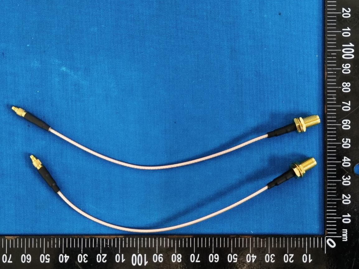
Report No.: 2510TW0109-UE 1 of 7 External Photograph (1) EUT Photo (WVL-A2458J28TTVX32_I_US) (2) EUT Photo (WVL-A2458J28TTVX32_I_US) Report No.: 2510TW0109-UE 2 of 7 (3) EUT Photo (WVL-A2458J28TTVX32_I_US) (4) EUT Photo (WVL-A2458J28TTVX32_I_US) Report No.: 2510TW0109-UE 3 of 7 (5) EUT Photo (WVL-A2458J28TTVX32_I_US) (6) EUT Photo (WVL-A2458J28TTVX32_I_US) Report No.: 2510TW0109-UE 4 of 7 (7) EUT Photo (WVL-A2458J28TTVX32_S_US) (8) EUT Photo (WVL-A2458J28TTVX32_S_US) Report No.: 2510TW0109-UE 5 of 7 (9) EUT Photo (WVL-A2458J28TTVX32_S_US) (10) EUT Photo (WVL-A2458J28TTVX32_S_US) Report No.: 2510TW0109-UE 6 of 7 (11) EUT Photo (WVL-A2458J28TTVX32_S_US) (12) EUT Photo (WVL-A2458J28TTVX32_S_US) Report No.: 2510TW0109-UE 7 of 7 (13) Antenna Photo
Internal Photos
Report No.: 2510TW0109-UI 1 of 11 Internal Photograph (1) EUT Photo (WVL-A2458J28TTVX32_I_US) (2) EUT Photo (WVL-A2458J28TTVX32_I_US) Report No.: 2510TW0109-UI 2 of 11 (3) EUT Photo (WVL-A2458J28TTVX32_I_US) (4) EUT Photo (WVL-A2458J28TTVX32_I_US) Report No.: 2510TW0109-UI 3 of 11 (5) EUT Photo (WVL-A2458J28TTVX32_I_US) (6) EUT Photo (WVL-A2458J28TTVX32_I_US) Report No.: 2510TW0109-UI 4 of 11 (7) EUT Photo (WVL-A2458J28TTVX32_I_US) (8) EUT Photo (WVL-A2458J28TTVX32_I_US) Report No.: 2510TW0109-UI 5 of 11 (9) EUT Photo (WVL-A2458J28TTVX32_I_US) (10) EUT Photo (WVL-A2458J28TTVX32_I_US) Report No.: 2510TW0109-UI 6 of 11 (11) EUT Photo (WVL-A2458J28TTVX32_I_US) (12) EUT Photo (WVL-A2458J28TTVX32_S_US) Report No.: 2510TW0109-UI 7 of 11 (13) EUT Photo (WVL-A2458J28TTVX32_S_US) (14) EUT Photo (WVL-A2458J28TTVX32_S_US) Report No.: 2510TW0109-UI 8 of 11 (15) EUT Photo (WVL-A2458J28TTVX32_S_US) (16) EUT Photo (WVL-A2458J28TTVX32_S_US) Report No.: 2510TW0109-UI 9 of 11 (17) EUT Photo (WVL-A2458J28TTVX32_S_US) (18) EUT Photo (WVL-A2458J28TTVX32_S_US) Report No.: 2510TW0109-UI 10 of 11 (19) EUT Photo (WVL-A2458J28TTVX32_S_US) (20) EUT Photo (WVL-A2458J28TTVX32_S_US) Report No.: 2510TW0109-UI 11 of 11 (21) EUT Photo (WVL-A2458J28TTVX32_S_US) (22) EUT Photo (WVL-A2458J28TTVX32_S_US)
RF Exposure Info
MRT Technology (Taiwan) Co., Ltd Report No.: 2510TW0109-U3 Phone: +886-3-3288388 Repor t Vers ion: 1.0 Web: www.mrt-cert.com Issue Date: 2025-12-03 Page Number: 1 of 12 RF Exposure Evaluation Declaration FCC ID : 2AQVB-DN2458G Applicant : Taisync Technology Inc. Application Type : Certification Product : 2.4&5.8GHz HD Wireless Link Model No. : WVL-A2458J28TTVX32_I_US Series Model No. : WVL-A2458J28TTVX32_S_US Brand Name : Viulinx FCC Classification : Digital Transmission System (DTS) Unlicensed National Information Infrastructure (NII) Received Date : October 22, 2025 Test By : ( Owen Tsai ) Reviewed By : ( Paddy Chen ) Approved By : ( Chenz Ker) The test results relate only to the samples tested. The test results shown in the test report are traceable to the national/international standards through the calibration of the equipment and evaluated measurement uncertainty herein. The test report shall not be reproduced except in full without the written approval of MRT Technology (Taiwan) Co., Ltd. Report No.: 2510TW0109-U3 Page Number: 2 of 12 Revision History Report No. Version Description Issue Date Note 2510TW0109-U3 1.0 Original Report 2025-12-03 Report No.: 2510TW0109-U3 Page Number: 3 of 12 CONTENTS Description Page 1. INTRODUCTION ................................................................................................................... 5 1.1. Scope ........................................................................................................................ 5 1.2. MRT Test Location .................................................................................................... 5 2. PRODUCT INFORMATION ................................................................................................... 6 2.1. Feature of Equipment under Test .............................................................................. 6 2.2. Description of Available Antennas .............................................................................. 6 2.3. Device Classification .................................................................................................. 7 2.4. Applied Standards ..................................................................................................... 7 3. RF Exposure Evaluation ..................................................................................................... 8 3.1. Limits ......................................................................................................................... 8 3.2. MPE Exemptions ....................................................................................................... 9 3.3. Test Result of RF Exposure Evaluation .....................................................................12 Report No.: 2510TW0109-U3 Page Number: 4 of 12 General Information Applicant Taisync Technology Inc. Applicant Address 2051 Junction Ave. Ste 115, San Jose, CA 95131 Manufacturer Taisync Technology Inc. Manufacturer Address 2051 Junction Ave. Ste 115, San Jose, CA 95131 Test Site MRT Technology (Taiwan) Co., Ltd Test Site Address No. 38, Fuxing Second Rd., Guishan Dist., Taoyuan City 333, Taiwan (R.O.C) MRT FCC Registration No. 291082 Test Device Serial No. N/A Production Pre-Production Engineering Test Facility / Accreditations 1. MRT facility is a FCC registered (Reg. No. 291082) test facility with the site description report on file and is designated by the FCC as an Accredited Test Firm. 2. MRT facility is an IC registered (MRT Reg. No. 21723) test laboratory with the site description on file at Industry Canada. 3. MRT Lab is accredited to ISO 17025 by the Taiwan Accreditation Foundation (TAF Cert. No. 3261) in EMC, Telecommunications and Radio testing for FCC (Designation Number: TW3261), Industry Canada, EU and TELEC Rules. Report No.: 2510TW0109-U3 Page Number: 5 of 12 1. INTRODUCTION 1.1. Scope Measurement and determination of electromagnetic emissions (EMC) of radio frequency devices including intentional and/or unintentional radiators for compliance with the technical rules and regulations of the Federal Communications Commission and the Innovation, Science and Economic Development Canada and Certification and Engineering Bureau. 1.2. MRT Test Location The map below shows the location of the MRT LABORATORY, its proximity to the Taoyuan City. These measurement tests were conducted at the MRT Technology (Taiwan) Co., Ltd. Facility located at No.38, Fuxing 2nd Rd., Guishan Dist., Taoyuan City 33377, Taiwan (R.O.C). Report No.: 2510TW0109-U3 Page Number: 6 of 12 2. PRODUCT INFORMATION 2.1. Feature of Equipment under Test Note: 1. Model Difference: WVL-A2458J28TTVX32_S_US is SMA connector, WVL-A2458J28TTVX32_I_US is IPEX connector, the other hardware was the same. (declared by the manufacturer) 2. The test was performed base on WVL-A2458J28TTVX32_I_US. 2.2. Description of Available Antennas No. Manufacturer Part No. Antenna Type Peak Gain 1 Be-Comfortable N12-7419-R0A Dipole 2.4G: 5.02dBi 5.8G: 4.95dBi Product Name: 2.4&5.8GHz HD Wireless Link Model No. WVL-A2458J28TTVX32_I_US Series Model No. WVL-A2458J28TTVX32_S_US Specification SRD 2.4GHz & 5.8GHz Report No.: 2510TW0109-U3 Page Number: 7 of 12 2.3. Device Classification According to the user manual, this device is classified as a Mobile Device. So, the RF exposure evaluation requirements of § 2.1091 for mobile device exposure conditions subject to MPE limits. 2.4. Applied Standards According to the specifications of the manufacturer, the EUT must comply with the requirements of the following standards: FCC Part 2.1091 & KDB 447498 D04 Interim General RF Exposure Guidance v01 Report No.: 2510TW0109-U3 Page Number: 8 of 12 3. RF Exposure Evaluation 3.1. Limits According to FCC 1.1310: The criteria listed in the following table shall be used to evaluate the environment impact of human exposure to radio frequency (RF) radiation as specified in 1.1307(b) Limits For Maximum Permissible Exposure (MPE) Frequency Range (MHz) Electric…
Text truncated - open the document above for the full version.
Test Report
MRT Technology (Taiwan) Co., Ltd Report No.: 2510TW0109-U1 Phone: +886-3-3288388 R ep or t Ver s i on: 1.0 Fax: +886-3-3288918 Issue Date: 2025-12-03 Web: www.mrt-cert.com Page Number: 1 of 77 FCC ID : 2AQVB-DN2458G APPLICANT : Taisync Technology Inc. Application Type : Certification Product : 2.4&5.8GHz HD Wireless Link Model No. : WVL-A2458J28TTVX32_I_US Series Model No. : WVL-A2458J28TTVX32_S_US Brand Name : Viulinx FCC Classification : (DTS) Digital Transmission System FCC Rule Part(s) : Part 15.247 Test Procedure(s) : ANSI C63.10-2020+Cor 1-2023+C63.10a-2024 + Errata to C63.10a-2024 Received Date : October 22, 2025 Test Date : October 23, 2025~November 6, 2025 MEASUREMENT REPORT Tested By : ( Kaunaz Lee ) Reviewed By : ( Paddy Chen ) Approved By : ( Chenz Ker) The test results only relate to the tested sample. This equipment has been shown to be capable of compliance with the applicable technical standards as indicated in the measurement report and was tested in accordance with the measurement procedures specified in ANSI C63.10. Test results reported herein relate only to the item(s) tested. The test report shall not be reproduced except in full without the written approval of MRT Technology (Taiwan) Co., Ltd. Report No.: 2510TW0109-U1 Page Number: 2 of 77 Revision History Report No. Version Description Issue Date Note 2510TW0109-U1 1.0 Original Report 2025-12-03 Report No.: 2510TW0109-U1 Page Number: 3 of 77 CONTENTS Description Page 1. INTRODUCTION ..................................................................................................................... 6 1.1. Scope .................................................................................................................................... 6 1.2. MRT Test Location ................................................................................................................ 6 2. PRODUCT INFORMATION ..................................................................................................... 7 2.1. Equipment Description .......................................................................................................... 7 2.2. Product Specification Subjective to this Standard .................................................................. 8 2.3. Test Mode ............................................................................................................................. 8 2.4. Operation Frequency / Channel List ...................................................................................... 9 2.5. Test Configuration ............................................................................................................... 10 2.6. Test System Details ............................................................................................................ 10 2.7. Test Software ...................................................................................................................... 10 2.8. Duty Cycles ......................................................................................................................... 11 2.9. EMI Suppression Device(s)/Modifications ........................................................................... 11 2.10. Labeling Requirements.................................................................................................... 11 3. DESCRIPTION of TEST ........................................................................................................ 12 3.1. Evaluation Procedure .......................................................................................................... 12 3.2. AC Line Conducted Emissions ............................................................................................ 12 3.3. Radiated Emissions ............................................................................................................ 13 4. ANTENNA REQUIREMENTS ................................................................................................ 14 5. TEST EQUIPMENT CALIBRATION DATE ............................................................................ 15 6. MEASUREMENT UNCERTAINTY ......................................................................................... 16 7. TEST RESULT ...................................................................................................................... 17 7.1. Summary ............................................................................................................................. 17 7.2. 6dB Bandwidth Measurement ...................................................…
Text truncated - open the document above for the full version.
Contact Information
Applicant
Yan Li
[email protected]Fax: 888-217-9882
Technical Contact
MRT Technology (Suzhou) Co., LtdMarlin Chen
[email protected]Fax: 86-512-66308368
D8 Building, Youxin Industrial Park, · China
Test Firm
MRT Technology (Taiwan) Co.,LtdChenz Ker
[email protected]Fax: +886-3-328-8918
Technical Specifications
| # | Rule Parts | Frequency Range | Power Output |
|---|---|---|---|
| 1 | 15C | 2.41 GHz - 2.47 GHz | 380.00 mW |
Other Applications from Taisync Technology Inc.
2AQVB-P241F
Feb 17, 20262.4GHz HD Wireless Link
Equipment Class
DTS - Digital Transmission System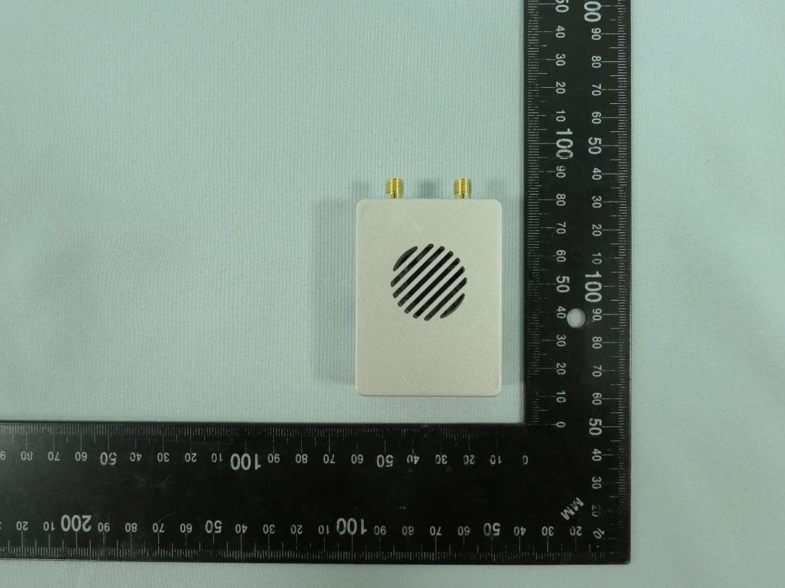
2AQVB-DN2458A
Feb 09, 2025Video&Data transmission device
Equipment Class
NII - Unlicensed National Information Infrastructure TX