2ARPE-SAFW004SSmart Large Display Radio Clock
Shenzhen Juku Intelligent Technology Co., Ltd.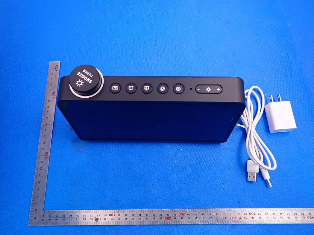
Click to zoom
Application Details
- Equipment Class
- DTS - Digital Transmission System
- Date of Grant
- Feb 23, 2021
- Application Purpose
- Original Equipment
- Date of Application
- Feb 23, 2021
- Equipment Note
- Smart Large Display Radio Clock
- Frequency Range
- 2412.00000000 - 2462.00000000
- Country
- China
Documents & Files
Document Text
Text extracted from the exhibit documents filed with the FCC. Open a document above to read the original.
Users Manual
Productcharacteristics Smartscreenalarmclockradiomanual Excellentdesignandqualityofproducts Nine-inchlargewhiteLEDtimedisplay,brightnesscanbeadjustedtoautomaticallyadjust thebrightnessaccordingtotheenvironment,orthelightsensitivepersoncompletelyoffthe uniquedesignofthebottomindirectwarmlight,canadjustthebrightnessbetween1-10 levels,provideyouwithsoftwarmlightingFMradioprovidesfastautomaticsearch,and maximumstorageof60stations,supporttoconnect3.5mmheadphonesandvolume adjustment Twosetsofseparatealarmclocks,equippedwith4naturalmusic,supportradiowake-up, andthealarmclockcanbeadjustedaccordingtotheworkingdayandrestdayrepeat cycle Softlightsfadeandprofessionalwhitenoiseorradiosleepwith10-120minutestoadjust, withtheendofthesleepcanautomaticallyturnoffthesoundandlights Richfeatures,provideambienttemperatureand month,day,weekandotherinformationdisplay timeformatsupport12/24Hsystem,12Hsystem, screendisplayAM/PMnetworktime,supporttime zoneanddaylightsavingtime VoiceandAPPcontrolalarmclocks,sleepersandlights Model SAFW004-S Size220×126.6×71.6mm Weight374g Color Black MaterialABS+PC、metal Control mode keystrokecontrol,APPcontrol,voicecontrol(linkthirdparty smartaudio) InputDC5V2A Productparameters OperationalGuidelines Displayicon description alarmclockclockclockclockclosingperiod closingperiod Between,the iconflashes. Partner Brighttogoto sleeptoclosethe Seticonflashduring sleep Gotosleep: ChangLiang Close,icon goesout Month Japan Annex Period(1)The dateofthedistributionperiodis Definition settings) Stars From Period Dynamic Display School S howtime(graphsupport:self-display Brokennetworkstate, iconextinguished. Wdistributioninetwork-Fshapemap statemark:thermalpunctuationfast matchingflashnetwork;shapedistribution Freq uen Temperature,degrees /Thephonograph shows"frequency°Frate";theicon Component;secondPMpoint;default recognitionnetflicker,long. Pressthe Always AM between; / Supportdisplay1 figure2/2standard4:Hnetwork Timedisplay Beautifulwhite9-inchsizeLEDdigital display,timeisclear Thebrightnesscanbeadjustedto automaticallyadjustthebrightness accordingtotheenvironmentor completelyturnoffthelightsensitive person Supportmonth,week,dateinformation display Support12/24Hsystem,12Hsystem, screendisplayAM/PMnetworktime, supporttimezoneanddaylightsavingtime OutputUSBAoutput5V1A Power10W(MAX) SpeakerΩ3W4 Packing List Smartscreenalarmclockradio,manual,adapter(optional), chargingline(optional) Nightlight Nightlightswitch:lightpressthetopofthe device"knob",canturnon/offthenight light. Cancooperatewiththeuseof+/-key,adjust thebrightnessofnightlights. Ifyouwakeupatnight,gentlypressthetop knoboftheproducttoturnonthenightlight, andthesoftlightintensityprovidedbythe faintamberlightjustallowsyoutoseethe roadinthedark. CanyoualsouseAPP settings:nightlightson,off, name,brightness Radio CanusethedevicetolistentoFMradio,or youcansetyourfavoriteradiostationto wakeupalarmclocksoundorsleepsound. Youcan: ClicktheFMkeytoturnon/offFMradio; PresstheFMkey,searchthestation automatically,andstorethefrequencyof theradiostationtotheradiostationlist onebyone(maximumstorageof60 stations); Intheradiolist,quicklyrotatetheknob toquicklyswitchtothenextvalidradio station; Slowturnknob,canbe0.1Hzforunit increment,declinetoadjustthefrequency, manualtable;(intheadjustment,suchas "MHz"flashinginstructionssearchtothe validtable); Supportconnection 3.5mmheadset;can beusedinAPPFM. Sleep Youcangentlypressthe"sleepwith"button atthetopofthedevicetoopenthesleep withsleep.Duringsleep,thelightisdimmed, andthesoundeffectisweakeneduntil completelyclosed. Youcan: Clickthesleepbuttontoturnon/offsleep; Pressthesleepbuttonlongandstartsetting thesleepsoundtypeS01-S04andF05(FM canbesleepsound).Adjustradiofrequency withknob; Usesiderollertoadjustsleepingsoundsize; Clickthesleepbuttonagaintosetthe brightnessofthesleepinglightL01-L10,and usetheknobtoadjustthebrightness; Clickthesleepbuttonagain,setthesleep time,thedefaultsleeptime30min,with theuseofknobadjustmenttime;(pressthe sleepbuttontoconfirmthesettings,while sleepingopen,backtothemainpage)can besetintheAPPwithsleepmusicand volume MusicEffect:Willitturnoff automaticallyattheendof gradual,gradualornormal sleep APP control Wakeupalarmclock Twosetsofindependentwake-upalarm clock,alarmtimearrived,withthealarm clockorradioring,youcanwakeupmore easilyandnaturally.Youcan: Clickthealarmkeytoturnon/offthealarm clock; Alwayspressthealarmclockkey,set thealarmclocktime,settheHH:MM; withtheknob Pressagain,setalarmsoundtype,useknob toadjust ;(S01-S06defaultalarmclockringing) When"F07""isdisplayed,pressthealarm clockagainandchooseFMradioasalarm. Adjustradiofrequencywithknob; Adjustthesoundofthealarmclockwith thesideroller;(pressthealarmclock buttontoconfirmthesetting,whilethe alarmclockisturnedon,backtothemain page)cansetthealarmclocktime,name, repeatintheAPP(workingday/restday/ day); Alarmclocksound:default6setsofalarm clockringorradio,volume; Soundeffect:strongor normal;soundtime; Sleepyswitch,mode,time. Sleepy Whenthealarmclockrings,youcangently pressthesleepbuttonatthetopofthe deviceandtakeanap.Duringsleep,the soundbecomesweaker9minuteslater,the alarmclockwillringagain. Youcanset: Sleepinterval Sleepinessturnsoffalarmmusic supportAPPcontrolthedetailedsettingof alarmclock,sleepandradio.Distribution NetworkGuidelines Downloadclient AQRcodedownloadinstallationApp.forsearching"Smart Life"orscanninginstructionsintheappstoreAndroiduser:can search"SmartLife"download"inGooglePlay; IOSusers:cansearchtheIOSAPPStore"SmartLife"download,; Forthefirstdownload,pleaseclickthe"Registration"buttontoregistertheaccount;if thereisanaccount,clickthe"login"button. Forthefirstdownload,pleaseclickthe"Registration"buttontoregistertheaccount;ifthere isanaccount,clickthe"login"button. Distributionnetworkrequirements Thebindingdevicedistributionnetworkneedstoopenthephonelocation,BluetoothandWi- F(Ionlysupport2.4G),allowingthephonetoaccessAPPlocationpermissions.Distribution NetworkMode[1AutomaticDiscovery/2ManualAdd(Wi-FiExpress,HotspotDistribu…
Text truncated - open the document above for the full version.
Cover Letter(s)
Shenzhen Juku Intelligent Technology Co., Ltd. Jan.08, 2021 Office of Engineering Technology Federal Communications Commission 7435 Oakland Mills Road Columbia, MD 21046 USA Subject: Explanation of differences between product types FCC ID : 2ARPE-SAFW004S Model Number: SAFW004S, SAFW004B, BW-LAC1, BW-LAC2, BW-LAC3 To Whom It May Concern: We, The Shenzhen Juku Intelligent Technology Co., Ltd. hereby declare that the model : SAFW004B, BW-LAC1, BW-LAC2, BW-LAC3 is identical with the model : SAFW004S, except the model name. Except for the different above, no other modification is performed. Sincerely, Signature: Shenzhen Juku Intelligent Technology Co., Ltd. Contact person: Ason Chen
Cover Letter(s)
Shenzhen Juku Intelligent Technology Co., Ltd. Agent Authorization Company: Shenzhen Juku Intelligent Technology Co., Ltd. Address: 303, Building 12, Jinshun Industrial Zone, No.20 Huancheng South Road, Ma'antang Community, Bantian street, Longgang District, Shenzhen, China Product Name: Smart Large Display Radio Clock Model Number(s): SAFW004S, SAFW004B, BW-LAC1, BW-LAC2, BW-LAC3 Product Description: Smart Large Display Radio Clock We authorize MiCOM Labs Inc., 575 Boulder Court, Pleasanton, California 94566, USA, to act on our behalf on all matters concerning the certification of above named equipment. We declare that MiCOM Labs Inc. is allowed to forward all information related to the approval and certification of equipment to the regulatory agencies as required and to discuss any issues concerning the approval application. Any and all acts carried out by MiCOM Labs on our behalf shall have the same effect as acts of our own. Signature: Date: 2021-01-08 Name: Ason Chen Company: Shenzhen Juku Intelligent Technology Co., Ltd.
Cover Letter(s)
Shenzhen Juku Intelligent Technology Co.,Ltd. Office of Engineering Technology Federal Communications Commission 7435 Oakland Mills Road Columbia, MD 21046 USA Date: 2021-01-07 Subject; Request for Confidentiality FCC ID: 2ARPE-SAFW004S To Whom It May Concern, Pursuant to the provisions of the Commission’s rules Title 47 Sections §0.457 and §0.459, we are requesting the Commission to withhold the following attachment(s) as confidential documents from public disclosure indefinitely. These documents contain detailed system and equipment descriptions and are considered as proprietary information in operation of the equipment. The public disclosure of these documents might be harmful to our company and would give competitors an unfair advantage in the market. Schematic Diagram Block Diagram Parts List Operational Description Tune-up Procedure In additional to above mentioned documents, in order to comply with the marketing regulations in Title 47 CFR §2.803 and the importation rules in Title 47 CFR §2.1204, while ensuring that business sensitive information remains confidential until the actual marketing of newly authorized devices, we request Short Term Confidentiality of the following attachment(s); External Photos Test Setup Photos Internal Photos User Manual For 45 days, pursuant to Public Notice DA 04-1705. OR For 180 days pursuant to KDB 726920 D01. It is our understanding that all measurement test reports, FCC ID label format and correspondence during the certification review process cannot be granted as confidential documents and this information will be available for public review once the grant of equipment authorization is issued. Sincerely Shenzhen Juku Intelligent Technology Co.,Ltd. Contact person: Ason Chen
External Photos
External Photos ALL VIEW OF EUT TOP VIEW OF EUT BOTTOM VIEW OF EUT FRONT VIEW OF EUT BACK VIEW OF EUT LEFT VIEW OF EUT RIGHT VIEW OF EUT VIEW OF EUT (PORT)-1 VIEW OF EUT (PORT)-2 VIEW OF EUT (PORT)-3
ID Label/Location Info
FCC ID Label Location FCC ID: 2ARPE-SAFW004S
Internal Photos
Internal Photos OPEN VIEW OF EUT-1 INTERNAL VIEW OF EUT-1 INTERNAL VIEW OF EUT-2 INTERNAL VIEW OF EUT-3 INTERNAL VIEW OF EUT-4 INTERNAL VIEW OF EUT-5 INTERNAL VIEW OF EUT-6 INTERNAL VIEW OF EUT-7 FM Antenna INTERNAL VIEW OF EUT-8 INTERNAL VIEW OF EUT-9 INTERNAL VIEW OF EUT-10 INTERNAL VIEW OF EUT-11 INTERNAL VIEW OF EUT-12 INTERNAL VIEW OF EUT-13 INTERNAL VIEW OF EUT-14 INTERNAL VIEW OF EUT-15 INTERNAL VIEW OF EUT-16 WIFI Antenna
RF Exposure Info
RF EXPOSURE EVALUATION 1. PRODUCT INFORMATION Product Description Smart Large Display Radio Clock Model Name SAFW004S, SAFW004B, BW-LAC1, BW-LAC2, BW-LAC3 FCC ID 2ARPE-SAFW004S 2. EVALUATION METHOD AND LIMIT Human exposure to RF emissions from mobile devices (47 CFR §2.1091) may be evaluated based on the MPE limits adopted by the FCC for electric and magnetic field strength and/or power density, as appropriate, since exposures are assumed to occur at distances of 20 cm or more from persons. LIMITS FOR GENERAL POPULATION / UNCONTROLLED EXPOSURE Frequency Range (MHz) E-field Strength (E) (V/m) Magnetic Field Strength (H) (A/m) Power Density (S) (mW/cm 2 ) Averaging Time |E| 2 , |H| 2 or S (Minutes) 0.3 -- 1.34 614 1.63 (100)* 30 1.34 -- 30 824/f 2.19/f (180/f 2 )* 30 30 -- 300 27.5 0.073 0.2 30 300 -- 1500 -- -- f/1500 30 1500 -- 100,000 -- -- 1.0 30 *Note: 1. f= Frequency in MHz * Plane-wave Equivalent Power Density 2. The averaging time for General Population/Uncontrolled exposure to fixed transmitters is not applicable for mobile and portable transmitters. See 47 CFR §§2.1091 and 2.1093 on source-based time-averaging requirement for mobile and portable transmitters. S=PG/4πR² Where: S=power density P=power input to antenna G=power gain of the antenna in the direction of interest relative to an isotropic radiator R=distance to the center of radiation of the antenna CALCULATION A minimum test separation distance ≥ 20 cm is required between the antenna and radiating structures of the device and nearby persons to apply mobile device exposure limits. The distance must be at least 20 cm and fully supported by the operating and installation configurations of the transmitter and its antenna(s), according to the source-based time-averaged maximum power requirements of § 2.1091(d)(2). In cases where cable losses or other attenuations are applied to determine compliance, the most conservative operating configurations and exposure conditions must be evaluated. 2.4G WIFI Antenna Gain=1.0dBi (Numeric 1.26), π=3.14 Note: 1. Only the worst case recorded. 3. conclusion Compliance the RF exposure requirement Frequency Output Power Output Power Power Density Power Density Limit MHz dBm mW mW/cm 2 mW/cm 2 2412 15.65 36.73 0.0092 1
Test Report
Page 1 of 82 Report No.: AGC09264201202FE05 FCC ID : 2ARPE-SAFW004S APPLICATION PURPOSE : Original Equipment PRODUCT DESIGNATION : Smart Large Display Radio Clock BRAND NAME : N/A MODEL NAME : SAFW004S, SAFW004B, BW-LAC1, BW-LAC2, BW-LAC3 APPLICANT : Shenzhen Juku Intelligent Technology Co., Ltd DATE OF ISSUE : Jan. 06, 2021 STANDARD(S) TEST PROCEDURE(S) : FCC Part 15.247 REPORT VERSION : V1.0 Attestation of Global Compliance (Shenzhen) Co., Ltd FCC Test Report Report No.: AGC09264201202FE05 Page 2 of 82 EPORT REVISE RECORD Report Version Revise Time Issued Date Valid Version Notes V1.0 / Jan. 06, 2021 Valid Initial Release Report No.: AGC09264201202FE05 Page 3 of 82 TABLE OF CONTENTS 1. VERIFICATION OF CONFORMITY ............................................................................................................... 5 2. GENERAL INFORMATION ............................................................................................................................ 6 2.1. PRODUCT DESCRIPTION ..................................................................................................................... 6 2.2. TABLE OF CARRIER FREQUENCYS ..................................................................................................... 6 2.3. IEEE 802.11N MODULATION SCHEME .................................................................................................. 7 2.4. RELATED SUBMITTAL(S) / GRANT (S) .................................................................................................. 7 2.5. TEST METHODOLOGY .......................................................................................................................... 7 2.6. SPECIAL ACCESSORIES ....................................................................................................................... 7 2.7. EQUIPMENT MODIFICATIONS .............................................................................................................. 7 2.8. ANTENNA REQUIREMENT .................................................................................................................... 8 3. MEASUREMENT UNCERTAINTY ................................................................................................................. 9 4. DESCRIPTION OF TEST MODES ............................................................................................................... 10 5. SYSTEM TEST CONFIGURATION ............................................................................................................. 11 5.1. CONFIGURATION OF EUT SYSTEM .................................................................................................... 11 5.2. EQUIPMENT USED IN EUT SYSTEM .................................................................................................... 11 5.3. SUMMARY OF TEST RESULTS ............................................................................................................. 11 6. TEST FACILITY ........................................................................................................................................... 12 7. OUTPUT POWER ........................................................................................................................................ 13 7.1. MEASUREMENT PROCEDURE ........................................................................................................... 13 7.2. TEST SET-UP (BLOCK DIAGRAM OF CONFIGURATION) ................................................................... 13 7.3. LIMITS AND MEASUREMENT RESULT ............................................................................................... 14 8. 6 DB BANDWIDTH ...................................................................................................................................... 15 8.1. MEASUREMENT PROCEDURE ........................................................................................................... 15 8.2. TEST SET-UP (BLOCK DIAGRAM OF CONFIGURATION) ................................................................... 15 8.3. LIMITS AND MEASUREMENT RESULTS ............................................................................................. 16 9. CONDUCTED SPURIOUS EMISSION ........................................................................................................ 22 Report No.: AGC09264201202FE05 Page 4 of 82 9.1. MEASUREMENT PROCEDURE ........................................................................................................... 22 9.2. TEST SET-UP (BLOCK DIAGRAM OF CONFIGURATION) ................................................................... 22 9.3. MEASUREMENT EQUIPMENT USEDJN ............................................................................................. 22 9.4. LIMITS AND MEASUREMENT RESULT ............................................................................................... 22 10. MAXIMUM CONDUCTED OUTPUT POWER SPECTRAL DENSITY ....................................................... 35 10.1 MEASUREMENT PROCEDURE .......................................................................................................... 35 10.2 TEST SET-UP (BLOCK DIAGRAM OF CONFIGURATION) .................................................................. 35 10.3 MEASUREMENT EQUIPMENT USED ................................................................................................. 35 10.4 LIMITS AND MEASUREMENT RESULT .............................................................................................. 35 11. RADIATED EMISSION ............................................................................................................................... 42 11.1. MEASUREMENT PROCEDURE ......................................................................................................... 42 11.2. TEST SETUP ...........................................................................................................................…
Text truncated - open the document above for the full version.
Test Report
Report No.: AGC09264201202FE05 Page 41 of 82 TEST PLOT OF SPECTRAL DENSITY FOR HIGH CHANNEL Report No.: AGC09264201202FE05 Page 42 of 82 11. RADIATED EMISSION 11.1. MEASUREMENT PROCEDURE 1. The EUT was placed on the top of the turntable 0.8 or 1.5 meter above ground. The phase center of the receiving antenna mounted on the top of a height-variable antenna tower was placed 3 meters far away from the turntable. 2. Power on the EUT and all the supporting units. The turntable was rotated by 360 degrees to determine the position of the highest radiation. 3. The height of the broadband receiving antenna was varied between one meter and four meters above ground to find the maximum emissions field strength of both horizontal and vertical polarization. 4. For each suspected emissions, the antenna tower was scan (from 1 M to 4 M) and then the turntable was rotated (from 0 degree to 360 degrees) to find the maximum reading. 5. Set the test-receiver system to Peak or CISPR quasi-peak Detect Function with specified bandwidth under Maximum Hold Mode. 6. For emissions above 1GHz, use 1MHz RBW and 3MHz VBW for peak reading. Place the measurement antenna away from each area of the EUT determined to be a source of emissions at the specified measurement distance, while keeping the measurement antenna aimed at the source of emissions at each frequency of significant emissions, with polarization oriented for maximum response. The measurement antenna may have to be higher or lower than the EUT, depending on the radiation pattern of the emission and staying aimed at the emission source for receiving the maximum signal. The final measurement antenna elevation shall be that which maximizes the emissions. The measurement antenna elevation for maximum emissions shall be restricted to a range of heights of from 1 m to 4 m above the ground or reference ground plane. 7. When the radiated emissions limits are expressed in terms of the average value of the emissions, and pulsed operation is employed, the measurement field strength shall be determined by averaging over one complete pulse train, including blanking intervals, as long as the pulse train does not exceed 0.1 seconds. As an alternative (provided the transmitter operates for longer than 0.1 seconds) or in cases where the pulse train exceeds 0.1 seconds, the measured field strength shall be determined from the average absolute voltage during a 0.1 second interval during which the field strength is at its maximum values. 8.If the emissions level of the EUT in peak mode was 3 dB lower than the average limit specified, then testing will be stopped and peak values of EUT will be reported, otherwise, the emissions which do not have 3 dB margin will be repeated one by one using the quasi-peak method for below 1GHz. 9. For testing above 1GHz, the emissions level of the EUT in peak mode was lower than average limit (that means the emissions level in peak mode also complies with the limit in average mode), then testing will be stopped and peak values of EUT will be reported, otherwise, the emissions will be measured in average mode again and reported. 10. In case the emission is lower than 30MHz, loop antenna has to be used for measurement and the recorded data should be QP measured by receiver. High - Low scan is not required in this case. Report No.: AGC09264201202FE05 Page 43 of 82 11.2. TEST SETUP Radiated Emission Test-Setup Frequency Below 30MHz RADIATED EMISSION TEST SETUP 30MHz-1000MHz RADIATED EMISSION TEST SETUP ABOVE 1000MHz Report No.: AGC09264201202FE05 Page 44 of 82 11.3. LIMITS AND MEASUREMENT RESULT 15.209(a) Limit in the below table has to be followed Frequencies (MHz) Field Strength (micorvolts/meter) Measurement Distance (meters) 0.009~0.490 2400/F(KHz) 300 0.490~1.705 24000/F(KHz) 30 1.705~30.0 30 30 30~88 100 3 88~216 150 3 216~960 200 3 Above 960 500 3 Note: All modes were tested For restricted band radiated emission, the test records reported below are the worst result compared to other modes. 11.4. TEST RESULT RADIATED EMISSION BELOW 30MHZ The amplitude of spurious emissions from 9kHz to 30MHz which are attenuated more than 20 dB below the permissible value need not be reported. Report No.: AGC09264201202FE05 Page 45 of 82 RADIATED EMISSION BELOW 1GHZ EUT Smart Large Display Radio Clock Model Name SAFW004S Temperature 25°C Relative Humidity 60% Pressure 960hPa Test Voltage Normal Voltage Test Mode 802.11b with date rate 1 2412MHZ Antenna Horizontal NO. Freq. [MHz] Level [dBμV/m] Factor [dB] Limit [dBμV/m] Margin [dB] Height [cm] Angle [°] Polarity 1 104.6900 31.66 11.86 43.50 11.84 200 4 Horizontal 2 133.7900 31.79 14.42 43.50 11.71 200 359 Horizontal 3 191.9900 38.48 12.43 43.50 5.02 200 359 Horizontal 4 217.2100 35.99 13.11 46.00 10.01 200 190 Horizontal 5 315.1800 35.63 16.48 46.00 10.37 100 339 Horizontal 6 366.5900 30.77 18.50 46.00 15.23 200 253 Horizontal RESULT: PASS Report No.: AGC09264201202FE05 Page 46 of 82 EUT Smart Large Display Radio Clock Model Name SAFW004S Temperature 25°C Relative Humidity 60% Pressure 960hPa Test Voltage Normal Voltage Test Mode 802.11b with date rate 1 2412MHZ Antenna Vertical NO. Freq. [MHz] Level [dBμV/m] Factor [dB] Limit [dBμV/m] Margin [dB] Height [cm] Angle [°] Polarity 1 52.3100 29.48 11.49 40.00 10.52 100 292 Vertical 2 99.8400 27.20 11.30 43.50 16.30 100 285 Vertical 3 129.9100 28.42 14.14 43.50 15.08 100 178 Vertical 4 159.9800 29.91 14.94 43.50 13.59 100 342 Vertical 5 224.0000 33.10 13.59 46.00 12.90 100 70 Vertical 6 265.7100 28.21 15.04 46.00 17.79 100 6 Vertical RESULT: PASS Note: 1. Factor=Antenna Factor + Cable loss, Margin=Limit-Level. 2. The “Factor” value can be calculated automatically by software of measurement system. 3. All test modes had been pre-tested. The 802.11b at low channel is the worst case and recorded in the report. Report No.: AGC09264201202FE05 Page 47 of 82 RADIATED EMISSION ABOVE 1GHZ EUT Smart Large Display Radio Clock Model Name SAFW004S Temperature 25°C Relative Humid…
Text truncated - open the document above for the full version.
Test Report
Report No.: AGC09264201202FE05 Page 72 of 82 RIGHT VIEW OF EUT VIEW OF EUT (PORT)-1 Report No.: AGC09264201202FE05 Page 73 of 82 VIEW OF EUT (PORT)-2 VIEW OF EUT (PORT)-3 Report No.: AGC09264201202FE05 Page 74 of 82 OPEN VIEW OF EUT-1 INTERNAL VIEW OF EUT-1 Report No.: AGC09264201202FE05 Page 75 of 82 INTERNAL VIEW OF EUT-2 INTERNAL VIEW OF EUT-3 Report No.: AGC09264201202FE05 Page 76 of 82 INTERNAL VIEW OF EUT-4 INTERNAL VIEW OF EUT-5 Report No.: AGC09264201202FE05 Page 77 of 82 INTERNAL VIEW OF EUT-6 INTERNAL VIEW OF EUT-7 FM Antenna Report No.: AGC09264201202FE05 Page 78 of 82 INTERNAL VIEW OF EUT-8 INTERNAL VIEW OF EUT-9 Report No.: AGC09264201202FE05 Page 79 of 82 INTERNAL VIEW OF EUT-10 INTERNAL VIEW OF EUT-11 Report No.: AGC09264201202FE05 Page 80 of 82 INTERNAL VIEW OF EUT-12 INTERNAL VIEW OF EUT-13 Report No.: AGC09264201202FE05 Page 81 of 82 INTERNAL VIEW OF EUT-14 INTERNAL VIEW OF EUT-15 Report No.: AGC09264201202FE05 Page 82 of 82 INTERNAL VIEW OF EUT-16 VIEW OF ADAPTER ----END OF REPORT---- WIFI Antenna Conditions of Issuance of Test Reports 1. All samples and goods are accepted by the Attestation of Global Compliance (Shenzhen) Co., Ltd (the “Company”) solely for testing and reporting in accordance with the following terms and conditions. The company provides its services on the basis that such terms and conditions constitute express agreement between the company and any person, firm or company requesting its services (the “Clients”). 2. Any report issued by Company as a result of this application for testing services (the “Report”) shall be issued in confidence to the Clients and the Report will be strictly treated as such by the Company. It may not be reproduced either in its entirety or in part and it may not be used for advertising or other unauthorized purposes without the written consent of the Company. The Clients to whom the Report is issued may, however, show or send it, or a certified copy thereof prepared by the Company to its customer, supplier or other persons directly concerned. The Company will not, without the consent of the Clients, enter into any discussion or correspondence with any third party concerning the contents of the Report, unless required by the relevant governmental authorities, laws or court orders. 3.The Company shall not be called or be liable to be called to give evidence or testimony on the Report in a court of law without its prior written consent, unless required by the relevant governmental authorities, laws or court orders. 4. The non-CMA report issued by AGC is only permitted to be used by the client as internal reference use and shall not be used for public demonstration purpose. 5. In the event of the improper use of the report as determined by the Company, the Company reserves the right to withdraw it, and to adopt any other additional remedies which may be appropriate. 6. Samples submitted for testing are accepted on the understanding that the Report issued cannot form the basis of, or be the instrument for, any legal action against the Company. 7. The Company will not be liable for or accept responsibility for any loss or damage however arising from the use of information contained in any of its Reports or in any communication whatsoever about its said tests or investigations. 8.Clients wishing to use the Report in court proceedings or arbitration shall inform the Company to that effect prior to submitting the sample for testing. 9. The Company is not responsible for recalling the electronic version of the original report when any revision is made to them. The Client assumes the responsibility to providing the revised version to any interested party who uses them. 10. Subject to the variable length of retention time for test data and report stored hereinto as otherwise specifically required by individual accreditation authorities, the Company will only keep the supporting test data and information of the test report for a period of six years. The data and information will be disposed of after the aforementioned retention period has elapsed. Under no circumstances shall we provide any data and information which has been disposed of after retention period. Under no circumstances shall we be liable for damage of any kind, including (but not limited to) compensatory damages, lost profits, lost data, or any form of special, incidental, indirect, consequential or punitive damages of any kind, whether based on breach of contract of warranty, tort (including negligence), product liability or otherwise, even if we are informed in advance of the possibility of such damages.
Test Setup Photos
Test Setup Photos FCC RADIATED EMISSION TEST SETUP BELOW 1GHZ FCC RADIATED EMISSION TEST SETUP ABOVE 1GHZ CONDUCTED EMISSION TEST SETUP
Contact Information
Applicant
Ason Chen
Technical Contact
Test Firm
Attestation of Global Compliance (Shenzhen) Co., LDoris Li
[email protected]+86-755-25234088
Technical Specifications
| # | Rule Parts | Frequency Range | Power Output |
|---|---|---|---|
| 1 | 15C | 2.41 GHz - 2.46 GHz | 151.70 mW |
Other Applications from Shenzhen Juku Intelligent Technology Co., Ltd.
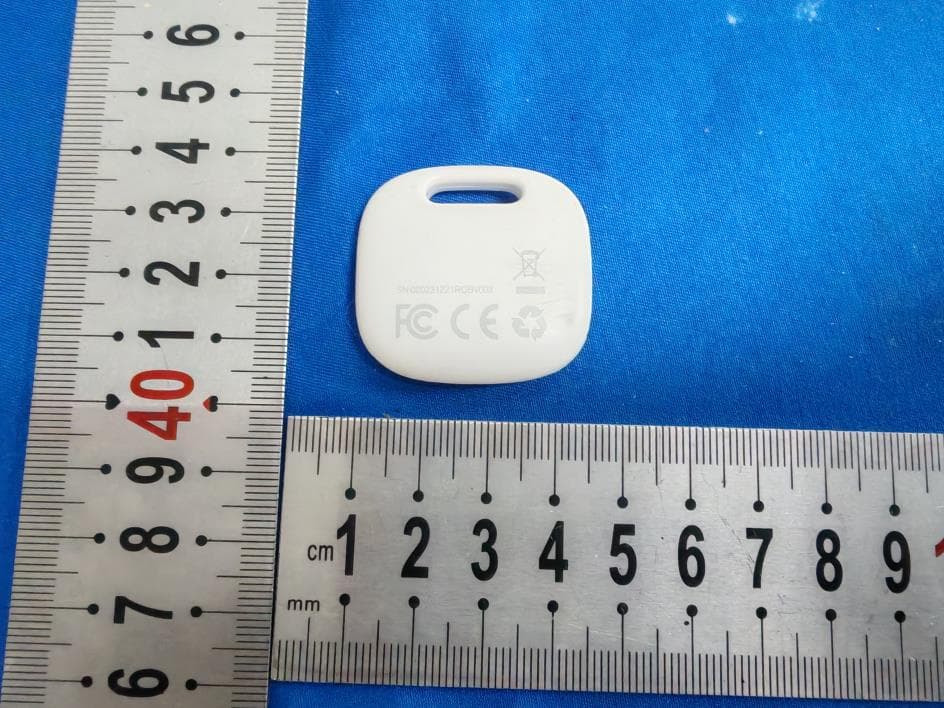
2ARPET2PRO
Sep 17, 2024Item Finder
Equipment Class
DTS - Digital Transmission System
2ARPE-SSM
Mar 23, 2024RestOn White Noise Wake-Up Light
Equipment Class
DTS - Digital Transmission System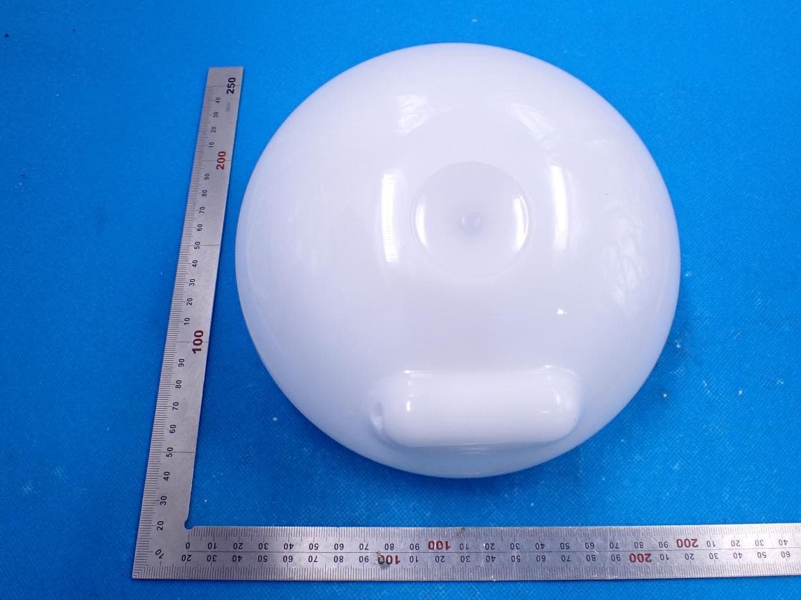
2ARPE-SAL
May 29, 2021Smart Ambiance Light
Equipment Class
DTS - Digital Transmission System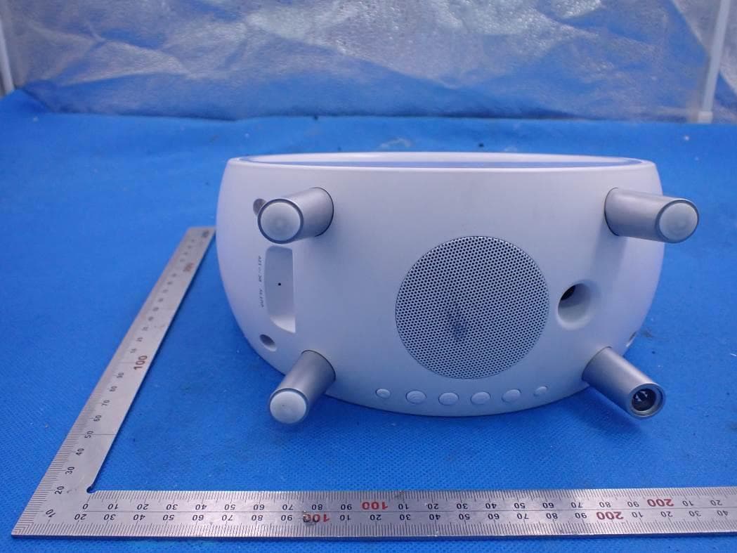
2ARPE-SAC
Mar 04, 2021Smart Ambiance Lamp With Alarm Clock
Equipment Class
DTS - Digital Transmission System
2ARPE-SNA006S
Feb 24, 2021Smart Night Light Alarm Clock
Equipment Class
DTS - Digital Transmission System