2ARPEWTHDWireless Indoor or Outdoor Humidity Aad Temperature Monitor
Shenzhen Juku Intelligent Technology Co., Ltd.
Click to zoom
Application Details
- Equipment Class
- DSC - Part 15 Security/Remote Control Transmitter
- Date of Grant
- Nov 25, 2020
- Application Purpose
- Original Equipment
- Date of Application
- Nov 25, 2020
- Equipment Note
- Wireless Indoor or Outdoor Humidity Aad Temperature Monitor
- Frequency Range
- 433.92400000 - 433.92400000
- Country
- China
Documents & Files
Document Text
Text extracted from the exhibit documents filed with the FCC. Open a document above to read the original.
Users Manual
Table of contentIntroduction Wireless Indoor or Outdoor Humidity And Temperature Monitor User Guide Please read this manual carefully before usingthe product and keep it in a safe place for future reference. 1.Introduction.....................................................................................................1 2.Precaution........................................................................................................1 3.Main machine features....................................................................................2 4.Auxiliary machine features.............................................................................3 5.Battery replacement and product placement..............................................4 6.Main machine & auxiliary machine synchronization and installation........6 7.Main machine & auxiliary machine placement.............................................7 8.Temperature & humidity trend.......................................................................7 9.Maximum & minimum recorded temperature & humidity...........................8 10.Comfort level icon display............................................................................8 11.Package list....................................................................................................9 12.Specification..................................................................................................9 13.Troubleshooting..........................................................................................10 14.Certification.................................................................................................11 Indoor temperature and humidity monitor main machine (hereby called main machine) Indoor/Outdoor wireless remote sensor auxiliary machine (hereby called auxiliary machine) Thanks for your purchase of the Wireless Indoor or Outdoor Humidity And Temperature Monitor. You can place the auxiliary machine indoor or outdoor, and the collected data will be transmit- ted to the main machine indoor to let you know the indoor or outdoor temperature and humidity changes from the screen on the main machine. Indoor humidity and temperature monitor main machine x 1 Indoor/Outdoor remote sensor auxiliary machine x 1 User guide x 1 3M adhesive tape x 1 Main machine featuresPackage list Top view Back view Front view Back view Auxiliary machine featuresBattery replacement and product placement Main machine battery replacement Main machine placement Main machine & auxiliary machine synchronization and installation 1.Press “MAX/MIN/CLEAR” to display the maximum or minimum temperature and humidity; 2.Press and hold “MAX/MIN/CLEAR” to clear the maximum or minimum history data, the buzzer will sound 3 times. 3.Press “MAX/MIN/CLEAR” , and then press “DISPLAY”, the buzzer will sound, indicating the maximum or minimum temperature and humidity of the corresponding auxiliary machine. If this equipment does cause harmful interference to radio or television reception, which can be determined by turning the equipment off and on, the user is encouraged to try to correct the interference by one or more of the following measures: • Reorient or relocate the receiving antenna. • Increase the separation between the equipment and the receiver. • Connect the equipment into an outlet on a circuit different from that to which the receiver is connected. • Consult the dealer or an experienced radio/TV technician for help. NOTE: The manufacturer is not responsible for any radio or TV interference caused by unauthorized modifications to this equipment. Such modifications could void the user authority to operate the equipment. Maximum & minimum recorded temperature & humidity 1.Place the main machine indoor. 2.Place the auxiliary machine indoor/outdoor. Make sure that the main machine and the auxiliary machine are within the communi- cation distance. 3.Press the " SYNC/PAIR" button on the main machine to enter the data synchronization mode, and the buzzer will sound; press the button on the auxiliary machine, the auxiliary machine transmits data to the main machine. After the main machine receive the data, the buzzer will sound 3 times; repeat the step of pressing the button on the auxiliary machine until the main machine can’t receive the data, the buzzer will no longer sound, indicating this is the optimal installation distance between the main machine and the auxiliary machine. Main machine & auxiliary machine installation Temperature & humidity trend Back view 2.Twist the battery cover counterclockwise to unlock 1.Lift the bracket4.Twist the battery cover clockwise to lock Auxiliary machine battery replacement Auxiliary machine placement 1.Twist the battery cover counterclockwise to unlock Twist the battery cover counterclockwise to unlock 3.Twist the battery cover clockwise to lock Twist the battery cover clockwise to lock This device complies with part 15 of FCC rules. Operation is subject to the following two conditions: 1- This device may NOT cause harmful interference, and 2- This device must accept any interference received, including interference that may cause undesired operation. WARNING: Changes or modifications to this unit not expressly approved by the party responsible for compliance could void the user’s authority to operate the equipment. NOTE: This equipment has been tested and found to comply with the limits for a Class B digital device, pursuant to Part 15 of the FCC rules. These limits are designed to provide reasonable protection against harmful interference in a residential installation. This equipment generates, uses and can radiate radio frequency energy and, if not installed and used in accordance with the instructions, may cause harmful interference to radio communications. However, there is no guarantee that interference will not occur in a particular installation. FCC Information Certification Wall mountMagnetically attached (to metal surfaces such as refrigerator and…
Text truncated - open the document above for the full version.
Cover Letter(s)
Shenzhen Juku Intelligent Technology Co., Ltd. Nov.19, 2020 Office of Engineering Technology Federal Communications Commission 7435 Oakland Mills Road Columbia, MD 21046 USA Subject: Explanation of differences between product types FCC ID : 2ARPEWTHD Model Number: WTHD, WTHD-01, WTHD-02, WTHD-03, WTHD3, WTHD3-01, WTHD3-02, WTHD3-03 To Whom It May Concern: We, The Shenzhen Juku Intelligent Technology Co., Ltd. hereby declare that the model : WTHD-01, WTHD-02, WTHD-03, WTHD3, WTHD3-01, WTHD3-02, WTHD3- 03 is identical with the model : WTHD, except the model name. Except for the different above, no other modification is performed. Sincerely, Signature: Shenzhen Juku Intelligent Technology Co., Ltd. Contact person: Ason Chen
Cover Letter(s)
Shenzhen Juku Intelligent Technology Co., Ltd. Agent Authorization Company: Shenzhen Juku Intelligent Technology Co., Ltd. Address: Room 303, Building 12, Jinshun Industrial Zone, No.20 Huancheng South Road, Ma'antang Community, Bantian street, Longgang District, Shenzhen, China Product Name: Wireless Indoor or Outdoor Humidity Aad Temperature Monitor Model Number(s): WTHD, WTHD-01, WTHD-02, WTHD-03, WTHD3, WTHD3-01, WTHD3-02, WTHD3-03 Product Description: Wireless Indoor or Outdoor Humidity Aad Temperature Monitor We authorize MiCOM Labs Inc., 575 Boulder Court, Pleasanton, California 94566, USA, to act on our behalf on all matters concerning the certification of above named equipment. We declare that MiCOM Labs Inc. is allowed to forward all information related to the approval and certification of equipment to the regulatory agencies as required and to discuss any issues concerning the approval application. Any and all acts carried out by MiCOM Labs on our behalf shall have the same effect as acts of our own. Signature: Date: 2020-11-19 Name: Ason Chen Company: Shenzhen Juku Intelligent Technology Co., Ltd.
Cover Letter(s)
Shenzhen Juku Intelligent Technology Co.,Ltd. Office of Engineering Technology Federal Communications Commission 7435 Oakland Mills Road Columbia, MD 21046 USA Date: 2020-10-15 Subject; Request for Confidentiality FCC ID: 2ARPEWTHD To Whom It May Concern, Pursuant to the provisions of the Commission’s rules Title 47 Sections §0.457 and §0.459, we are requesting the Commission to withhold the following attachment(s) as confidential documents from public disclosure indefinitely. These documents contain detailed system and equipment descriptions and are considered as proprietary information in operation of the equipment. The public disclosure of these documents might be harmful to our company and would give competitors an unfair advantage in the market. Schematic Diagram Block Diagram Parts List Operational Description Tune-up Procedure In additional to above mentioned documents, in order to comply with the marketing regulations in Title 47 CFR §2.803 and the importation rules in Title 47 CFR §2.1204, while ensuring that business sensitive information remains confidential until the actual marketing of newly authorized devices, we request Short Term Confidentiality of the following attachment(s); External Photos Test Setup Photos Internal Photos User Manual For 45 days, pursuant to Public Notice DA 04-1705. OR For 180 days pursuant to KDB 726920 D01. It is our understanding that all measurement test reports, FCC ID label format and correspondence during the certification review process cannot be granted as confidential documents and this information will be available for public review once the grant of equipment authorization is issued. Sincerely Shenzhen Juku Intelligent Technology Co.,Ltd. Contact person: Ason Chen
External Photos
External Photos TOP VIEW OF EUT BOTTOM VIEW OF EUT FRONT VIEW OF EUT BACK VIEW OF EUT LEFT VIEW OF EUT RIGHT VIEW OF EUT
ID Label/Location Info
FCC ID Label Location FCC ID: 2ARPEWTHD
Internal Photos
Internal Photos OPEN VIEW OF EUT INTERNAL VIEW-1 OF EUT INTERNAL VIEW-2 OF EUT INTERNAL VIEW-3 OF EUT Antenna
Test Report
Page 1 of 25 FCC Test Report Report No.: AGC09264200902FE03 FCC ID : 2ARPEWTHD APPLICATION PURPOSE : Original Equipment PRODUCT DESIGNATION : Wireless Indoor or Outdoor Humidity Aad Temperature Monitor BRAND NAME : N/A MODEL NAME : WTHD, WTHD-01, WTHD-02, WTHD-03, WTHD3, WTHD3-01, WTHD3-02, WTHD3-03 APPLICANT : Shenzhen Juku Intelligent Technology Co., Ltd. DATE OF ISSUE : Oct. 13, 2020 STANDARD(S) TEST PROCEDURE(S) : FCC Part 15 Subpart C Section 15.231 REPORT VERSION : V1.0 Attestation of Global Compliance (Shenzhen) Co., Ltd Report No.: AGC09264200902FE03 Page 2 of 25 Report Revise Record Report Version Revise Time Issued Date Valid Version Notes V1.0 / Oct. 13, 2020 Valid Initial release Report No.: AGC09264200902FE03 Page 3 of 25 TABLE OF CONTENTS 1. VERIFICATION OF CONFORMITY ............................................................................................................... 5 2. GENERAL INFORMATION ............................................................................................................................ 6 2.1. PRODUCT DESCRIPTION ..................................................................................................................... 6 2.2. TEST METHODOLOGY .......................................................................................................................... 6 2.3. ANTENNA REQUIREMENT .................................................................................................................... 6 3. MEASUREMENT UNCERTAINTY ................................................................................................................. 7 4. DESCRIPTION OF TEST MODES ................................................................................................................. 8 5. SYSTEM TEST CONFIGURATION ............................................................................................................... 8 5.1. CONFIGURATION OF EUT SYSTEM ..................................................................................................... 8 5.2. EQUIPMENT USED IN EUT SYSTEM ..................................................................................................... 8 5.3. SUMMARY OF TEST RESULTS .............................................................................................................. 8 6. TEST FACILITY ............................................................................................................................................. 9 7. TEST EQUIPMENT LIST ............................................................................................................................... 9 8. PROVISION FOR MOMENTARY OPERATION ........................................................................................... 10 8.1 MEASUREMENT PROCEDURE ............................................................................................................ 10 8.2 TEST SETUP .......................................................................................................................................... 10 8.3 TEST RESULT ......................................................................................................................................... 11 9. DUTY CYCLE CORRECTION FACTOR ...................................................................................................... 12 9.1 MEASUREMENT PROCEDURE ............................................................................................................ 12 9.2 TEST SETUP .......................................................................................................................................... 12 9.3 TEST RESULT ........................................................................................................................................ 12 10. RADIATED EMISSION ............................................................................................................................... 13 10.1. MEASUREMENT PROCEDURE ......................................................................................................... 13 10.2. TEST SETUP ....................................................................................................................................... 15 10.3. TEST RESULT ..................................................................................................................................... 16 11. BANDWIDTH ............................................................................................................................................. 18 11.1. MEASUREMENT PROCEDURE ......................................................................................................... 18 11.2. TEST SETUP ....................................................................................................................................... 18 11.3. TEST RESULT ..................................................................................................................................... 19 Report No.: AGC09264200902FE03 Page 4 of 25 APPENDIX A: PHOTOGRAPHS OF TEST SETUP ........................................................................................ 20 APPENDIX B: PHOTOGRAPHS OF EUT ....................................................................................................... 21 Report No.: AGC09264200902FE03 Page 5 of 25 1. VERIFICATION OF CONFORMITY Applicant Shenzhen Juku Intelligent Technology Co., Ltd. Address Room 303, Building 12, Jinshun Industrial Zone, No.20 Huancheng South Road, Ma'antang Community, Bantian Street, Longgang District, Shenzhen Manufacturer Shenzhen Juku Intelligent Technology Co., Ltd. Address Room 303, Building 12, Jinshun Industrial Zone, No.20 Huancheng South Road, Ma'antang Community, Bantian Street, Longgang District, Shenzhen Factory Shenzhen Juku Intelligent Technology Co., Ltd. Address Room 303, Building 12, Jinshun Industrial Zone, No.20 Huancheng South Road, Ma'antang Community, Ban…
Text truncated - open the document above for the full version.
Test Setup Photos
Test Setup Photos FCC RADIATED EMISSION TEST SETUP-BELOW 1GHz FCC RADIATED EMISSION TEST SETUP-ABOVE 1GHz
Contact Information
Applicant
Ason Chen
Technical Contact
Test Firm
Attestation of Global Compliance (Shenzhen) Co., LDoris Li
[email protected]+86-755-25234088
Technical Specifications
| # | Rule Parts | Frequency Range | Power Output |
|---|---|---|---|
| 1 | 15.231 | 433.924 MHz - 433.924 MHz | - |
Other Applications from Shenzhen Juku Intelligent Technology Co., Ltd.
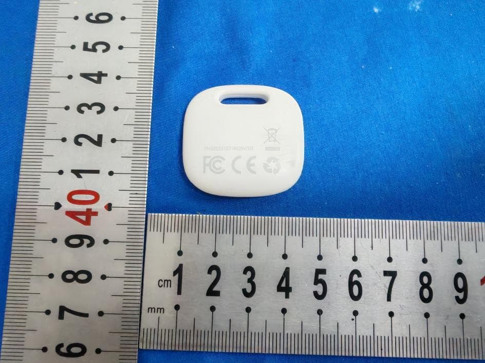
2ARPET2PRO
Sep 17, 2024Item Finder
Equipment Class
DTS - Digital Transmission System
2ARPE-SSM
Mar 23, 2024RestOn White Noise Wake-Up Light
Equipment Class
DTS - Digital Transmission System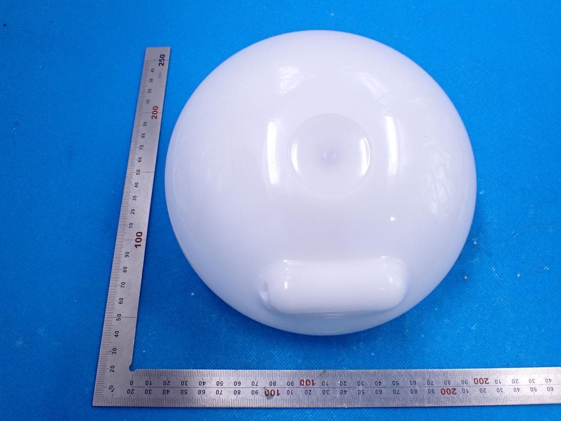
2ARPE-SAL
May 29, 2021Smart Ambiance Light
Equipment Class
DTS - Digital Transmission System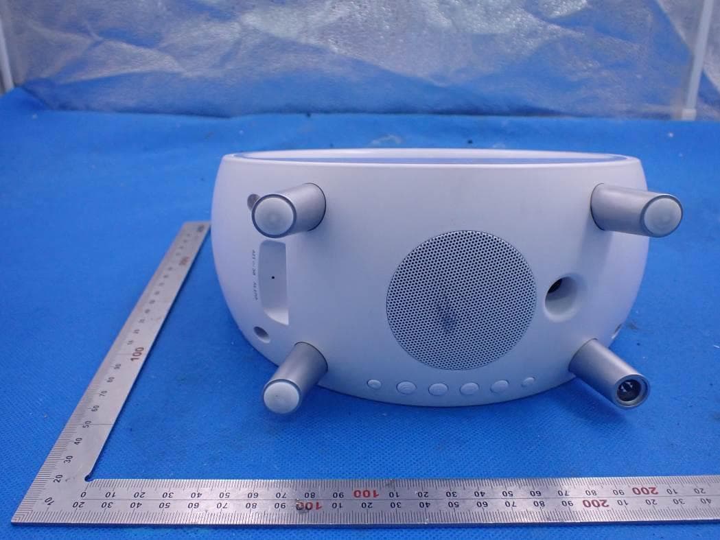
2ARPE-SAC
Mar 04, 2021Smart Ambiance Lamp With Alarm Clock
Equipment Class
DTS - Digital Transmission System
2ARPE-SNA006S
Feb 24, 2021Smart Night Light Alarm Clock
Equipment Class
DTS - Digital Transmission System