2ARVRWC074Qi Wireless Charging Pad
SHENZHEN DBK ELECTRONICS CO.,LTD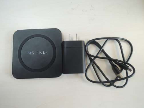
Click to zoom
Application Details
- Equipment Class
- DCD - Part 15 Low Power Transmitter Below 1705 kHz
- Date of Grant
- May 28, 2020
- Application Purpose
- Original Equipment
- Date of Application
- May 27, 2020
- Equipment Note
- Qi Wireless Charging Pad
- Frequency Range
- 0.11100000 - 0.20500000
- Country
- China
Documents & Files
Document Text
Text extracted from the exhibit documents filed with the FCC. Open a document above to read the original.
Users Manual
CARACTÉRISTIQUES • La sortie de 10 W, fournit une charge rapide des périphériques compatibles Qi • Modèle compact pratique à placer pour une charge fiable • La conception sans fil charge les périphériques sans câbles encombrants • La LED bleue indique que l'appareil est en cours de charge Avant l’utilisation de ce produit neuf, lire ces instructions afin d'éviter tout dommage. APERÇU DU PRODUIT UTILISATION DU SOCLE DE CHARGE 1 Connecter le câble de charge au socle de charge. 2 Connecter l'autre extrémité du câble à un port USB de l’ordinateur ou sur un adaptateur d'alimentation. En cas d’utilisation d'un adaptateur d’alimentation, brancher sur une prise secteur. 3 Placer l'appareil compatible Qi sur le centre du socle de charge avec l'écran tourné vers le haut. La DEL est bleue quand le périphérique est en cours de charge. Remarque : Si la DEL est rouge, l'appareil ne se charge pas. Se reporter à la section « Problèmes et solutions » pour plus d'informations. GUIDE D’INSTALLATION RAPIDE Chargeurs sans fil de 10 W NS-MWPC10K / NS-MWPC10KTP / NS-MWPC10K-C Flat size (W×H): 12 × 2.75 in. (304.8 x 69.85 mm) Final folded size: 3 × 2.75 in. (76.2 x 69.85 mm) CONTENU DE L'EMBALLAGE NS-MWPC10K / NS-MWPC10K-C • Socle de charge sans fil de 10 W certifié Qi (1) • Câble de charge de 1,2 m (4 pi) [1] • Adaptateur d'alimentation USB (1) • Guide d’installation rapide NS-MWPC10KTP • Socle de charge sans fil de 10 W certifié Qi (2) • Câble de charge de 1,2 m (4 pi) [2] • Adaptateur d'alimentation USB (2) • Guide d’installation rapide COMPATIBILITÉ Tout appareil compatible Qi d'une puissance maximale de 10 W, dont les téléphones intelligents, les casques d'écoute, les montres intelligentes. Cela inclut les derniers iPhone, Samsung Galaxy et les périphériques bloc-notes. Témoin DEL Panneau arrière Panneau avant Port micro USB Adaptateur d'alimentation USB CÂBLE de charge OU 3 2 NS-MWPC10KTP_20-0036_QSG_V1_FR_Final.ai 1 5/1/2020 9:37:02 AMNS-MWPC10KTP_20-0036_QSG_V1_FR_Final.ai 1 5/1/2020 9:37:02 AM
External Photos
Page 1 of 2 FCC ID: 2ARVRWC074 IC: 25947-WC074 Page 2 of 2 FCC ID: 2ARVRWC074 IC: 25947-WC074
Internal Photos
Page 1 of 2 FCC ID: 2ARVRWC074 IC: 25947-WC074 Page 2 of 2 FCC ID: 2ARVRWC074 IC: 25947-WC074
RF Exposure Info
FCC ID: 2ARVRWC074 1.1. Measuring Standard FCC CFR 47 Part 1(1.1310) KDB 680106 D01 v03 1.2. Requirements The EUT does comply with item 5(b) of KDB 680106 D01 v03 1) Power transfer frequency is less than 1MHz 2) Output power from each primary coil is less than or equal to 15 watts. 3) The transfer system includes only single primary and secondary coils. This includes charging systems that may have multiple primary coils and clients that able to detect and allow coupling only between individual pair of coils. 4) Client device is inserted in or placed directly in contact with the transmitter. 5) Mobile exposure conditions only (portable exposure conditions are not covered by this exclusion) 6) The aggregate H-field strengths at 15 cm surrounding the device and 20 cm above the top surface from all simultaneous transmitting coils are demonstrated to be less than 50% of the MPE limit. 1.3. Test Configuration 1) The field strength of both H-field was measured at 15cm using the equipment list above for determining compliance with the MPE requirements of FCC Part 1.1310. 2) The RF power density was measured at Under maximum load test 3) Maximum H-field measurements were made 15cm from each side of the EUT. Along the side of the EUT and still 15cm away from the edge of the EUT, the field probes were positioned at the location where there is maximum field strength. The maximum H-field is reported below. 4) This device uses a wireless charging circuit for power transfer operating at the frequency of 110 – 205 kHz. Thus, the 300kHz limits were used: H-field limit 1.63 (A/m). 1.4. Test Procedure 1) The RF exposure test was performed in anechoic chamber. 2) The aggregate H-field strengths at 15 cm surrounding the device and 20 cm above the top surface 3) The highest emission level was recorded and compared with limit as soon as measurement of each points (A, B, C, D, E) were completed. 4) The EUT was measured according to the dictates of KDB 680106 D01 v03. Remark: The EUT’s test position A, B, C, D, and E is valid for the H field measurements. 1.5. Test Setup 1.6. Limits Remark: Emissions between 100 kHz to 300 kHz should be assessed versus the limits at 300 kHz in Table 1 of Section 1.1310: 1.63 A/m 1.7. Measuring Device and Test Equipment For MPE Measurement Item Equipment Manufacturer Model No. Serial No. Last Cal. Cal. Interval 1. H-Field Probe 100 cm2 SENSOR narda D-0010 BN 2300/90.10 May 20, 2019 1 Year 2. MAGNETIC FIELD HiTESTER ELT- 400 narda D-0009 BN 2304/03 May 20, 2019 1 Year 1.8. Description of Test Facility Test Items : H field measurements Test Laboratory : TÜV Rheinland (Shenzhen) Co., Ltd. Site Location : East of F/1, F/2 - F/4, Building 1, Cybio Technology Building, No. 6 Langshan No. 2 Road, North Hi-tech Industry Park, Nanshan District, Shenzhen, P.R. China 1.9. Measuring Results Table: H-Field Strength at 15 cm from the edges surrounding the EUT and 20cm from the front surface of the EUT EUT Test Mode Measured H-Field Strength Values (A/m) 50% Limit (A/m) Limit (A/m) Test Position A (top) Test Position B(back) Test Position C(left) Test Position D (Right) Test Position E(Front) 1% Battery Level 0.268 0.245 0.250 0.221 0.226 0.815 1.63 50% Battery Level 0.252 0.216 0.227 0.211 0.217 0.815 1.63 99% Battery Level 0.246 0.224 0.234 0.218 0.221 0.815 1.63
Test Report
Produkte Products Prüfbericht-Nr.: Test report No.: 60362410 001 Auftrags-Nr.: Order No.: 168156015 Seite 1 von 24 P age 1 of 24 Kunden-Referenz-Nr.: Client reference No.: N/A Auftragsdatum: Order date: 13.03.2020 Auftraggeber: Client: SHENZHEN DBK ELECTRONICS CO.,LTD. Room No .208-1,308, 404-408 in Building Five, 2-4 Floor in Building Three, No.8 Qinghua Road, Zhu Village ,Fucheng New Community, Guanlan Street, Longhua District, Shenzhen City, Guangdong Province, P.R.China Prüfgegenstand: Test item: Qi Wireless Charging Pad Bezeichnung / Typ-Nr.: Identification / Type No.: NS-MWPC10K, NS-MWPC10K-C, NS-MWPC10KTP, NS-xxxxxxxxxx, MD- xxxxxxxxxx, PT- xxxxxxxxxx, DX- xxxxxxxxxx, RF- xxxxxxxxxx (“x” can be 0-9, A-Z, a-z, "-" or blank, for market purpose only, all models are identical except the model name or color) (Trademark: INSIGNIA, MODAL, Platinum, DYNEX, Rocketfish) Auftrags-Inhalt: Order content: FCC and IC approval Prüfgrundlage: Test specification: CFR47 FCC Part 15: Subpart C Section 15.207 CFR47 FCC Part 15: Subpart C Section 15.209 RSS-216 issue 2 January 2016 RSS-GEN issue 5 March 2019 RSS-102 issue 5 March 2015 Wareneingangsdatum: Date of receipt: 17.03.2020 Refer to photos document Prüfmuster-Nr.: Test sample No.: A001072446-018 to 019 Prüfzeitraum: Testing period: 18.03.2020 - 10.04.2020 Ort der Prüfung: Place of testing: TÜV Rheinland (Shenzhen) Co., Ltd. Prüflaboratorium: Testing laboratory: TÜV Rheinland (Shenzhen) Co., Ltd. Prüfergebnis*: Test result*: Pass geprüft von / tested by: kontrolliert von / reviewed by: 20.05.2020 Jonathan Li / Project Manager 20.05.2020 Sam Lin / Technical Certifier Datum Date Name/Stellung Name/Position Unterschrift Signature Datum Date Name/Stellung Name/Position Unterschrift Signature Sonstiges / Other: FCC ID: 2ARVRWC074 IC: 25947-WC074 HVIN: NS-MWPC10K-C Zustand des Prüfgegenstandes bei Anlieferung: Condition of the test item at delivery: Prüfmuster vollständig und unbeschädigt T est item complete and undamaged: * Legende: 1 = sehr gut 2 = gut 3 = befriedigend 4 = ausreichend 5 = mangelhalt P(ass) = entspricht o.g. Prüfgrundlage(n) F(ail) = entspricht nicht o.g. Prüfgrundlage(n) N/A = nicht anwendbar N/T = nicht getestet Legend: 1 = very good 2 = good 3 = satisfactory 4 = sufficient 5 = poor P(ass) = passed a.m. test specifications(s) F(ail) = failed a.m. test specifications(s) N/A = not applicable N/T = not tested Dieser Prüfbericht bezieht sich nur auf das o.g. Prüfmuster und darf ohne Genehmigung der Prüfstelle nicht auszugsweise vervielfältigt werden. Dieser Bericht berechtigt nicht zur Verwendung eines Prüfzeichens. This test report only relates to the a. m. test sample. Without permission of the test center this test report is not permitted to be V05 duplicated in extracts. This test report does not entitle to carry any test mark. TÜV Rheinland (Shenzhen) Co., Ltd., 1F East & 2-4F, Cybio Technology Building No.1, No.16 Langshan 2nd Road, High-Tech Industrial Park North Nanshan District, 518057, Shenzhen, China http://www.tuv.com Produkte Products Prüfbericht - Nr.: Test Report No. 60362410 001 Seite 2 von 24 Page 2 of 24 Test Summary 5.1.1 ANTENNA REQUIREMENT RESULT: Pass 5.1.2 99% BANDWIDTH RESULT: Pass 5.1.3 RADIATED EMISSIONS RESULT: Pass 5.1.4 CONDUCTED EMISSIONS RESULT: Pass Produkte Products Prüfbericht - Nr.: Test Report No. 60362410 001 Seite 3 von 24 Page 3 of 24 Contents 1 GENERAL REMARKS ........................................................................................................................... 4 1.1 COMPLEMENTARY MATERIALS ............................................................................................................ 4 2 TEST SITES ........................................................................................................................................ 5 2.1 TEST FACILITIES ................................................................................................................................. 5 2.2 LIST OF TEST AND MEASUREMENT INSTRUMENTS................................................................................. 5 2.3 TRACEABILITY .................................................................................................................................... 6 2.4 CALIBRATION ..................................................................................................................................... 6 2.5 MEASUREMENT UNCERTAINTY............................................................................................................. 7 2.6 LOCATION OF ORIGINAL DATA ............................................................................................................. 7 2.7 STATUS OF FACILITY USED FOR TESTING ............................................................................................. 7 3 GENERAL PRODUCT INFORMATION ...................................................................................................... 8 3.1 PRODUCT FUNCTION AND INTENDED USE ............................................................................................. 8 3.2 RATINGS AND SYSTEM DETAILS .......................................................................................................... 8 3.3 INDEPENDENT OPERATION MODES ...................................................................................................... 8 3.4 NOISE GENERATING AND NOISE SUPPRESSING PARTS ......................................................................... 8 3.5 SUBMITTED DOCUMENTS..................................................................................................................... 8 4 TEST SET-UP AND OPERATION MODES ................................................................................................ 9 4.1 PRINCIPLE OF CONFIGURATION SELECTION ......................................................................................... 9 4.2 TEST OPERATION AND TEST SOFTWARE ...................................................…
Text truncated - open the document above for the full version.
Test Setup Photos
MPE test photo
Test Setup Photos
Produkte Products Appe ndix A 60362410 001 Page 1 of 3 Appendix A: Photographs of the Test Set-Up APPENDIX A: PHOTOGRAPHS OF THE TEST SET-UP.................................................................................................................. 1 PHOTOGRAPH 1: SET-UP PHOTO FOR RADIATED EMISSION, 9KHZ - 30MHZ......................................................................................... 2 PHOTOGRAPH 2: SET-UP PHOTO FOR RADIATED EMISSION, 30MHZ - 1GHZ ........................................................................................ 2 PHOTOGRAPH 3: SET-UP PHOTO FOR CONDUCTED EMISSION ON AC MAINS ......................................................................................... 3 Produkte Products Appe ndix A 60362410 001 Page 2 of 3 Photograph 1: Set-up photo for Radiated Emission, 9KHz - 30MHz Photograph 2: Set-up photo for Radiated Emission, 30MHz - 1GHz Produkte Products Appe ndix A 60362410 001 Page 3 of 3 Photograph 3: Set-up photo for Conducted Emission on AC Mains
Contact Information
Applicant
Peng Shi(R&D director)
Test Firm
TUV Rheinland (Shenzhen) Co., Ltd.Gina Yang
[email protected]86 755 8268 1497
Technical Specifications
| # | Rule Parts | Frequency Range | Power Output |
|---|---|---|---|
| 1 | 15C | 0.111 MHz - 0.205 MHz | - |
Other Applications from SHENZHEN DBK ELECTRONICS CO.,LTD
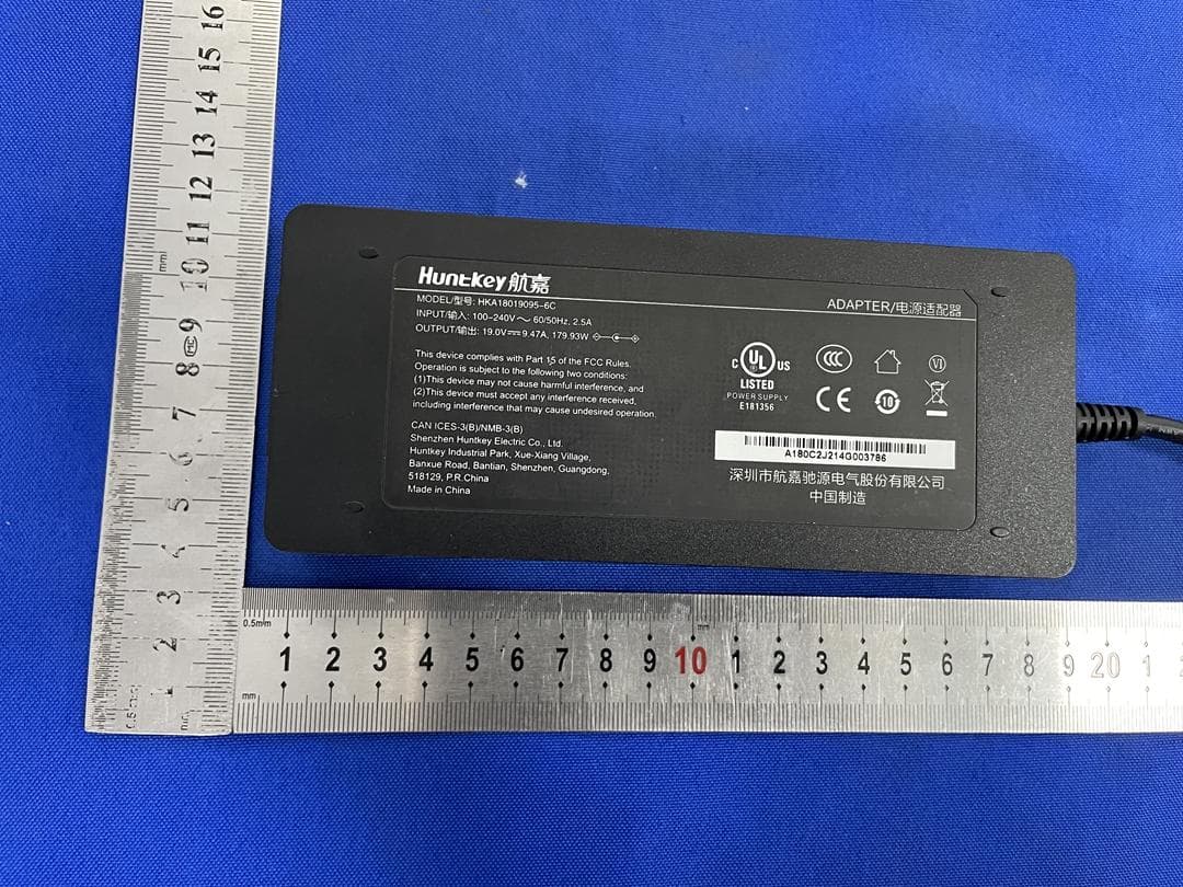
2ARVR-BLACKBEE1000
Jun 08, 2022Portable Power Station
Equipment Class
DCD - Part 15 Low Power Transmitter Below 1705 kHz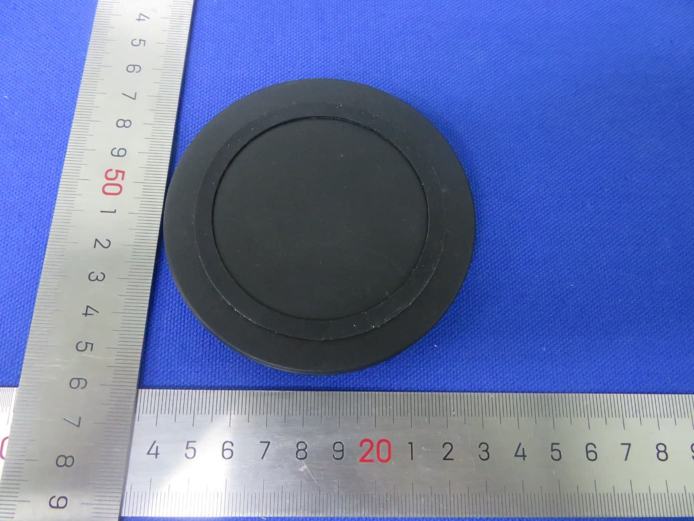
2ARVRCP610L
Apr 27, 2021QI Wireless Charging Pad
Equipment Class
DCD - Part 15 Low Power Transmitter Below 1705 kHz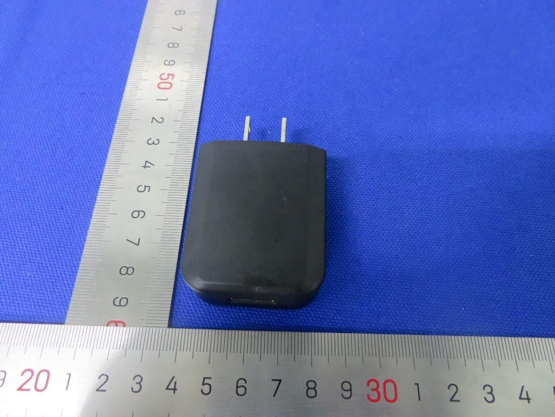
2ARVRWC073
May 24, 2020Q i Wireless Charging Pad
Equipment Class
DCD - Part 15 Low Power Transmitter Below 1705 kHz