2AS3F-WWD2SMWireless Wall Dimmer
Current Lighting Solutions, LLC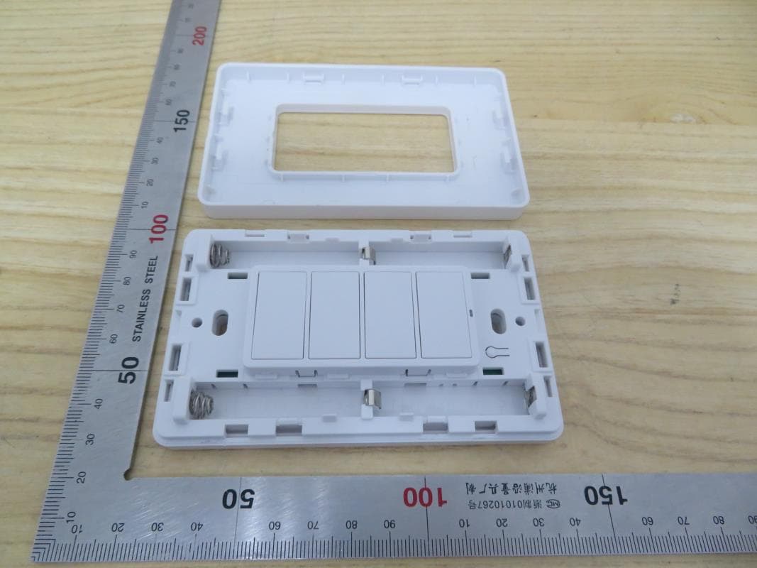
Click to zoom
Application Details
- Equipment Class
- DTS - Digital Transmission System
- Date of Grant
- Apr 14, 2021
- Application Purpose
- Original Equipment
- Date of Application
- Apr 14, 2021
- Equipment Note
- Wireless Wall Dimmer
- Frequency Range
- 2405.00000000 - 2480.00000000
- Country
- United States
Documents & Files
Document Text
Text extracted from the exhibit documents filed with the FCC. Open a document above to read the original.
Users Manual
Installation Guide 2 Installation Use a standard screwdriver to open the faceplate, Pull the plastic insulation strip out of the battery compartment. Install the faceplate onto the device. Note: Device supports the use of other standard faceplates on the market. To reset the network of the device, remove the faceplate from the device. Then press and hold the reset button for 5 seconds. Install the faceplate back onto the device. Press either dimming up or down button to enter the pairing mode to join the device to a network. If you want to install on the junction box, use the screw in the package and a cross screwdriver to lock the device on the junction box Network Reset 1 2 3 If you want to install the device on the wall, use the 3M tape in the package to stick the device firmly on the wall. 4 Surface Mounting, 2 Buttons Daintree® Networked Wireless Wall Dimmer (WWD2) You can also handheld use the device in the CSM signal cover area. 5 Battery Replacement Installation Guide 3 Product Dimensions 1 2 3 4 The device’s LED flashing every 30 seconds indicates that the batteries need to be replaced. Use a standard screwdriver to open the faceplate Install the faceplate onto the device. Separate the battery cover from the device. Replace the batteries with AAA batteries. All batteries need to be replaced at the same time. Surface Mounting, 2 Buttons Daintree® Networked Wireless Wall Dimmer (WWD2) Installation Guide 4 Product Overview Technical Data Dimensions Weight Power Supply battery life Operating Environment Status indicator Mounting Warranty SKUDESCRIPTIONARTICLE NO. WWD2-2SM FCC ID: 2AS3F-WWD2SM IC : 25008-WWD2SM 5yr (normal operation) 114mm H x 70mm W x 15mm D 130g (4) AAA1.5V battery -10°C to 40°C Indoor Use Only) Network joined/Button triggered Surface mounted, screw hole in backplate, cover could be removed, handheld 5 years 93141315 Product Specifications Product CertificationsProduct Availablity Daintree® Networked Wireless Wall Dimmer Surface Mounting, 2 Buttons Daintree® Networked Wireless Wall Dimmer (WWD2) Operating Control E486320 www.gecurrent.com © 2020 Current Lighting Solutions, LLC. All rights reserved. GE and the GE monogram are trademarks of the General Electric Company and are used under license. Information provided is subject to change without notice. All values are design or typical values when measured under laboratory conditions. CTRL027 (Rev 07/05/20) Enovia - A-1025984 Installation Guide Surface Mounting, 2 Buttons Daintree® Networked Wireless Wall Dimmer (WWD2) Caution: The user is cautioned that changes or modifications not expressly approved by the party responsible for compliance could void the user's authority to operate the equipment. Note: This equipment has been tested and found to comply with the limits for a Class B digital device, pursuant to part 15 of the FCC Rules. These limits are designed to provide reasonable protection against harmful interference in a residential installation. This equipment generates uses and can radiate radio frequency energy and, if not installed and used in accordance with the instructions, may cause harmful interference to radio communications. However, there is no guarantee that interference will not occur in a particular installation. If this equipment does cause harmful interference to radio or television reception, which can be determined by turning the equipment off and on, the user is encouraged to try to correct the interference by one or more of the following measures: —Reorient or relocate the receiving antenna. —Increase the separation between the equipment and receiver. —Connect the equipment into an outlet on a circuit different from that to which the receiver is connected. —Consult the dealer or an experienced radio/TV technician for help Suppliers phone number and / or internet contact information: 1-866-855-8629 Suppliers Name: Current Lighting Solutions, LLC Suppliers Address (USA): 1975 Noble Road, East Cleveland, OH 44112 Model No: WWD2-2SM Porduct Name: This device complies with Part 15 of the FCC Rules. Operation is subject to the following two conditions: (1) This device may not cause harmful interference, and (2) this device must accept any interference received, including interference that may cause undesired operation. Wireless Wall Dimmer Supplier's Declaration of Conformity 47 CFR § 2.1077 Compliance Information
Users Manual
Installation Guide 2 Installation To reset the network of the device, remove the faceplate from the device. Then press and hold the reset button for 5 seconds. Install the faceplate back onto the device. Press either dimming up or down button to enter the pairing mode to join the device to a network. Network Reset 1 2 3 4 Surface Mounting, 4 Buttons Use a standard screwdriver to open the faceplate, Pull the plastic insulation strip out of the battery compartment. Install the faceplate onto the device. Note: Device supports the use of other standard faceplates on the market. If you want to install on the junction box, use the screw in the package and a cross screwdriver to lock the device on the junction box If you want to install the device on the wall, use the 3M tape in the package to stick the device firmly on the wall. Daintree® Networked Wireless Wall Dimmer (WWD2) You can also handheld use the device in the CSM signal cover area. 5 Installation Guide 2 Personality Change 1 2 Hold the reset button and 2nd button for 5sec to change the personality to dual zone mode. Hold the reset button and 4st button for 5sec to change the personality to scene mode. Button Change 1 2 Take off the button module from the devices. Take off the single button and replace another one you want. 3 Psl contact your agent if you want to customize the button. Surface Mounting, 4 Buttons Daintree® Networked Wireless Wall Dimmer (WWD2) Battery Replacement Installation Guide 3 Product Dimensions 1 2 3 4 The device’s LED flashing every 30 seconds indicates that the batteries need to be replaced. Use a standard screwdriver to open the faceplate Install the faceplate onto the device. Separate the battery cover from the device. Replace the batteries with AAA batteries. All batteries need to be replaced at the same time. Surface Mounting, 4 Buttons Daintree® Networked Wireless Wall Dimmer (WWD2) Installation Guide 4 Product Overview Technical Data Dimensions Weight Power Supply battery life Operating Environment Status indicator Mounting Warranty SKUDESCRIPTIONARTICLE NO. WWD2-4SM 5yr (normal operation) 114mm H x 70mm W x 15mm D 130g (4) AAA1.5V battery -10°C to 40°C Indoor Use Only) Network joined/Button triggered Surface mounted, screw hole in backplate, cover could be removed, handheld 5 years 93141336 Product Specifications Product CertificationsProduct Availablity Daintree® Networked Wireless Wall Dimmer FCC ID: 2AS3F-WWD2SM IC : 25008-WWD2SM Surface Mounting, 4 Buttons Daintree® Networked Wireless Wall Dimmer (WWD2) Operating Control E486320 www.gecurrent.com © 2020 Current Lighting Solutions, LLC. All rights reserved. GE and the GE monogram are trademarks of the General Electric Company and are used under license. Information provided is subject to change without notice. All values are design or typical values when measured under laboratory conditions. CTRL027 (Rev 07/05/20) Enovia - A-1025984 Installation Guide Surface Mounting, 4 Buttons Daintree® Networked Wireless Wall Dimmer (WWD2) Caution: The user is cautioned that changes or modifications not expressly approved by the party responsible for compliance could void the user's authority to operate the equipment. Note: This equipment has been tested and found to comply with the limits for a Class B digital device, pursuant to part 15 of the FCC Rules. These limits are designed to provide reasonable protection against harmful interference in a residential installation. This equipment generates uses and can radiate radio frequency energy and, if not installed and used in accordance with the instructions, may cause harmful interference to radio communications. However, there is no guarantee that interference will not occur in a particular installation. If this equipment does cause harmful interference to radio or television reception, which can be determined by turning the equipment off and on, the user is encouraged to try to correct the interference by one or more of the following measures: —Reorient or relocate the receiving antenna. —Increase the separation between the equipment and receiver. —Connect the equipment into an outlet on a circuit different from that to which the receiver is connected. —Consult the dealer or an experienced radio/TV technician for help Suppliers phone number and / or internet contact information: 1-866-855-8629 Suppliers Name: Current Lighting Solutions, LLC Suppliers Address (USA): 1975 Noble Road, East Cleveland, OH 44112 Model No: WWD2-4SM Porduct Name: This device complies with Part 15 of the FCC Rules. Operation is subject to the following two conditions: (1) This device may not cause harmful interference, and (2) this device must accept any interference received, including interference that may cause undesired operation. Wireless Wall Dimmer Supplier's Declaration of Conformity 47 CFR § 2.1077 Compliance Information
Cover Letter(s)
1975 Noble Road, East Cleveland, Ohio 44112 www.gecurrent.com © 2021 Current Lighting Solutions, LLC. All rights reserved. GE is a trademark of the General Electric Company and is used under license. Jessica Browning Lead Power Electronics Engineer T +1 216 462 4540 [email protected] Federal Communications Commission 7435 Oakland Mills Road Columbia MD 21046 Subject: Request for Confidentiality FCC ID: 2AS3F-WWD2SM To Whom It May Concern: Pursuant to the provisions of Sections 0.457 and 0.459 of the Commission’s rules (47 CFR §§ 0.457, 0.459), we are requesting the Commission to withhold the following attachments as confidential document from public disclosure indefinitely. Schematic Diagram Block Diagram Theory of Operation Above mentioned document contains detailed system and equipment description are considered as proprietary information in operation of the equipment. The public disclosure of above documents might be harmful to our company and would give competitor an unfair advantage in the market. It is our understanding that all measurement test reports, FCC ID label format and correspondent during certification review process cannot be granted as confidential documents and those information will be available for public review once the grant of equipment authorization is issued. Best Regards Company Name: Current Lighting Solutions, LLC Contact Name: Jessica Browning Address: 1975 Noble Road, East Cleveland, OH 44112 Date: 03/24/2021
Cover Letter(s)
1975 Noble Road, East Cleveland, Ohio 44112 www.gecurrent.com © 2021 Current Lighting Solutions, LLC. All rights reserved. GE is a trademark of the General Electric Company and is used under license. Jessica Browning Lead Power Electronics Engineer T +1 216 462 4540 [email protected] Date: 03/24/2021 Federal Communications Commission 7435 Oakland Mills Road Columbia MD 21046 To whom it may concern: I, the undersigned, hereby authorize UL Verification Services Inc. to act on our behalf in all manners relating to application for equipment authorization, including signing of all documents relating to these matters. Any and all acts carried out by UL Verification Services Inc. on our behalf shall have the same effect as acts of our own. I, the undersigned, hereby certify that we are not subject to a denial of federal benefits, that includes FCC benefits, pursuant to Section 5301 of the Anti-Drug Abuse Act of 1988, 21 U.S.C. 853(a). In authorizing UL Verification Services Inc. as our representative, we still recognize that we are responsible to: a) comply with the relevant provisions of the certification program; b) make all necessary arrangements for the conduct of the evaluation, including provision for examining documentation and access to all areas, records (including internal audit reports) and personnel for the purposes of evaluation (e.g. testing, inspection, assessment, surveillance, reassessment) and resolution of complaints; c) make claims regarding certification only in respect of the scope for which certification has been granted; d) do not use our product certification in such a manner as to bring the Certification Division into disrepute and not make any statement regarding our product certification which the Certification Division may consider misleading or unauthorized; e) upon suspension or cancellation of certification, discontinue use of all advertising matter that contains any reference thereto and return any certification documents as required by the Certification Division; 1975 Noble Road, East Cleveland, Ohio 44112 www.gecurrent.com f) use certification only to indicate the products are certified as being in conformity with specified standards; g) endeavor to ensure that no certificate or report nor any part thereof is used in a misleading manner; h) ensure that any reference to our product certification in communication media such as documents, brochures or advertising, complies with the requirements of the Certification Division; i) keep a record of all complaints made known to us relating to the product’s compliance with requirements of the relevant standard and to make these records available to the when requested; j) take appropriate action with respect to such complaints and any deficiencies found in products or services that affect compliance with the requirements for certification; k) document the actions taken. This authorization is valid until June 30, 2021. Sincerely, Company Name: Current Lighting Solutions, LLC Contact Name: Jessica Browning Address: 1975 Noble Road, East Cleveland, OH 44112 Date: 03/24/2021
Cover Letter(s)
Current Lighting Solutions, LLC Address: 1975 Noble Road, East Cleveland, OH 44112 Confirmation Letter We, Current Lighting Solutions, LLC The product: Wireless Wall Dimmer And model No.: WWD2-2SM, WWD2-4SM FCC ID: 2AS3F-WWD2SM IC: 25008-WWD2SM WWD2-2SM have the same technical construction including circuit diagram, PCB Layout, components and component layout, all electrical construction and mechanical construction with WWD2-4SM. The difference lies only different number of buttons. all these changes do not degrade the unwanted emissions of the certified product. ______________________ Company Name: Current Lighting Solutions, LLC Contact Name: Jessica Browning Address: 1975 Noble Road, East Cleveland, OH 44112 Date: 03/24/2021
External Photos
Appendix I External Photographs Page 2 of 4 UL Verification Services (Guangzhou) Co., Ltd, Song Shan Lake Branch This report shall not be reproduced except in full, without the written approval of UL Verification Services (Guangzhou) Co., Ltd, Song Shan Lake Branch. View of EUT-1 View of EUT-2 Model:WWD2-4SM Model:WWD2-2SM Page 3 of 4 UL Verification Services (Guangzhou) Co., Ltd, Song Shan Lake Branch This report shall not be reproduced except in full, without the written approval of UL Verification Services (Guangzhou) Co., Ltd, Song Shan Lake Branch. View of EUT-3 View of EUT-4 Page 4 of 4 UL Verification Services (Guangzhou) Co., Ltd, Song Shan Lake Branch This report shall not be reproduced except in full, without the written approval of UL Verification Services (Guangzhou) Co., Ltd, Song Shan Lake Branch. View of EUT-5 View of EUT-6
ID Label/Location Info
3.5mm Wireless Wall Dimmer WWD2-2SM FCC ID: 2AS3F-WWD2SM IC: 25008-WWD2SM Ratings in Volts: 3VDC Operating Temperature Range: -10°C to 40°C FCC Par t 15 Class B CAN ICES-003 (B) / NMB-003 (B) RISK OF EXPLOSION IF BATTERY IS REPL ACED BY AN INCORRECT TYPE DISPOSE OF USED BATTERIES ACCORDING TO THE INSTRUCTIONS CAUTION ATTENTION RISQUE D’EXPLOSION SI L A PILE EST REMPL ACÉE PAR UN TYPE INCORRECT JETEZ LES PILES USAGÉES CONFORMÉMENT AUX INSTRUCTIONS #93141315YYYYMMDD Current Lighting Solutions, LLC www.gecurrent.com Made in China For assistance call 1-866-855-8629 8mm 1.5mm PS:typeface is Segoe UI,word size is 4pt YYYYMMDD,YYYY means year,MM means month,DD means day,for example:20210112 3.5mm Wireless Wall Dimmer WWD2-4SM FCC ID: 2AS3F-WWD2SM IC: 25008-WWD2SM Ratings in Volts: 3VDC Operating Temperature Range: -10°C to 40°C FCC Par t 15 Class B CAN ICES-003 (B) / NMB-003 (B) RISK OF EXPLOSION IF BATTERY IS REPL ACED BY AN INCORRECT TYPE DISPOSE OF USED BATTERIES ACCORDING TO THE INSTRUCTIONS RISQUE D’EXPLOSION SI L A PILE EST REMPL ACÉE PAR UN TYPE INCORRECT JETEZ LES PILES USAGÉES CONFORMÉMENT AUX INSTRUCTIONS CAUTION ATTENTION #93141336YYYYMMDD Current Lighting Solutions, LLC www.gecurrent.com Made in China For assistance call 1-866-855-8629 8mm 1.5mm
Internal Photos
Appendix II Internal Photographs Page 2 of 4 UL Verification Services (Guangzhou) Co., Ltd, Song Shan Lake Branch This report shall not be reproduced except in full, without the written approval of UL Verification Services (Guangzhou) Co., Ltd, Song Shan Lake Branch. Internal View of EUT-1 Internal View of EUT-2 Page 3 of 4 UL Verification Services (Guangzhou) Co., Ltd, Song Shan Lake Branch This report shall not be reproduced except in full, without the written approval of UL Verification Services (Guangzhou) Co., Ltd, Song Shan Lake Branch. Internal View of EUT-3 Internal View of EUT-4 Antenna Page 4 of 4 UL Verification Services (Guangzhou) Co., Ltd, Song Shan Lake Branch This report shall not be reproduced except in full, without the written approval of UL Verification Services (Guangzhou) Co., Ltd, Song Shan Lake Branch. Internal View of EUT-5 Model: WWD2-2SM Model: WWD2-4SM
RF Exposure Info
FCC ID: 2AS3F-WWD2SM According to KDB 447498 D01 General RF Exposure Guidance v06, section 4.3.1 At 100 MHz to 6 GHz and for test separation distances ≤ 50 mm, the SAR test exclusion threshold is determined according to the following [(max. power of channel, including tune-up tolerance, mW) / (min. test separation distance, mm)] x [√f(GHz)] ≤ 3.0 1. SAR test exclusion threshold Frequency: 2480MHz (min. separation distances = 5 mm) SAR test exclusion thresholds (5 mm) = 3 x 5 / (√ 2.480) = 9.525 mW Max. Tune-up Tolerance (mW) SAR Test Exclusion Thresholds (5mm) (mW) 5 9.525 Calculation Value: 5 (mW) / 5 (mm) x √ 2.480 = 1.579 So, Calculation value ≤ 3.0 Remark: -Max. conducted power 4.5 mW, so 5 mW was calculated. -When the minimum test separation distance is < 5 mm, a distance of 5 mm is applied to determine SAR test exclusion. 2. Conclusion: No SAR is required.
Test Report
The results reported herein have been performed in accordance with the laboratory’s terms of accreditation. This report shall not be reproduced except in full without the written approval of the Laboratory. The results in this report apply to the test sample(s) mentioned above at the time of the testing period only and are not to be used to indicate applicability to other similar products. CFR 47 FCC PART 15 SUBPART C ISED RSS-247 ISSUE 2 CERTIFICATION TEST REPORT For Wireless Wall Dimmer MODEL NUMBER: WWD2-4SM, WWD2-2SM FCC ID: 2AS3F-WWD2SM IC: 25008- WWD2SM REPORT NUMBER: 4789794026-1 ISSUE DATE: January 28, 2021 Prepared for Current Lighting Solutions, LLC 1975 Noble Road, East Cleveland, OH 44112 Prepared by UL Verification Services (Guangzhou) Co., Ltd, Song Shan Lake Branch Building 10, Innovation Technology Park, No. 1, Li Bin Road, Song Shan Lake Hi- Tech Development Zone Dongguan, 523808, People’s Republic of China Tel: +86 769 22038881 Fax: +86 769 33244054 Website: www.ul.com REPORT NO.: 4789794026-1 Page 2 of 69 UL Verification Services (Guangzhou) Co., Ltd, Song Shan Lake Branch FORM No.: 10-SL-F0087 This report shall not be reproduced except in full, without the written approval of UL Verification Services (Guangzhou) Co., Ltd, Song Shan Lake Branch. Revision History Rev. Issue Date Revisions Revised By V0 01/28/2021 Initial Issue REPORT NO.: 4789794026-1 Page 3 of 69 UL Verification Services (Guangzhou) Co., Ltd, Song Shan Lake Branch FORM No.: 10-SL-F0087 This report shall not be reproduced except in full, without the written approval of UL Verification Services (Guangzhou) Co., Ltd, Song Shan Lake Branch. Summary of Test Results Clause Test Items FCC/ISED Rules Test Results 1 6dB Bandwidth and 99% Occupied Bandwidth FCC Part 15.247 (a) (2) RSS-247 Clause 5.2 (a) ISED RSS-Gen Clause 6.7 Pass 2 Peak Conducted Output Power FCC Part 15.247 (b) (3) RSS-247 Clause 5.4 (d) Pass 3 Power Spectral Density FCC Part 15.247 (e) RSS-247 Clause 5.2 (b) Pass 4 Conducted Bandedge and Spurious Emission FCC Part 15.247 (d) RSS-247 Clause 5.5 Pass 5 Radiated Bandedge and Spurious Emission FCC Part 15.247 (d) FCC Part 15.209 FCC Part 15.205 RSS-247 Clause 5.5 RSS-GEN Clause 8.9 Pass 6 Antenna Requirement FCC Part 15.203 RSS-GEN Clause 6.8 Pass Note: 1.This test report is only published to and used by the applicant, and it is not for evidence purpose in China. 2. The measurement result for the sample received is <Pass> according to < CFR 47 FCC PART 15 SUBPART C >< ISED RSS-247 > when <Accuracy Method> decision rule is applied. REPORT NO.: 4789794026-1 Page 4 of 69 UL Verification Services (Guangzhou) Co., Ltd, Song Shan Lake Branch FORM No.: 10-SL-F0087 This report shall not be reproduced except in full, without the written approval of UL Verification Services (Guangzhou) Co., Ltd, Song Shan Lake Branch. TABLE OF CONTENTS 1. ATTESTATION OF TEST RESULTS ................................................................................. 6 2. TEST METHODOLOGY ..................................................................................................... 7 3. FACILITIES AND ACCREDITATION ................................................................................. 7 4. CALIBRATION AND UNCERTAINTY ................................................................................ 8 4.1. MEASURING INSTRUMENT CALIBRATION .............................................................. 8 4.2. MEASUREMENT UNCERTAINTY ............................................................................... 8 5. EQUIPMENT UNDER TEST ............................................................................................... 9 5.1. DESCRIPTION OF EUT .............................................................................................. 9 5.2. CHANNEL LIST ........................................................................................................... 9 5.3. MAXIMUM PEAK OUTPUT POWER ........................................................................... 9 5.4. TEST CHANNEL CONFIGURATION ........................................................................... 9 5.5. THE WORSE CASE POWER SETTING PARAMETER ..............................................10 5.6. DESCRIPTION OF AVAILABLE ANTENNAS .............................................................11 5.7. DESCRIPTION OF TEST SETUP ...............................................................................12 6. MEASURING INSTRUMENT AND SOFTWARE USED ....................................................13 7. ANTENNA PORT TEST RESULTS ...................................................................................15 7.1. ON TIME AND DUTY CYCLE .....................................................................................15 7.2. 6 dB DTS BANDWIDTH AND 99 % OCCUPIED BANDWIDTH ..................................16 7.3. CONDUCTED OUTPUT POWER ...............................................................................18 7.4. POWER SPECTRAL DENSITY ..................................................................................19 7.5. CONDUCTED BANDEDGE AND SPURIOUS EMISSIONS ........................................21 8. RADIATED TEST RESULTS .............................................................................................23 8.1. RESTRICTED BANDEDGE ........................................................................................29 8.2. SPURIOUS EMISSIONS (1 GHz ~ 3 GHz) .................................................................35 8.3. SPURIOUS EMISSIONS (3 GHz ~ 18 GHz) ...............................................................41 8.4. SPURIOUS EMISSIONS (18 GHz ~ 26 GHz) .............................................................47 8.5. SPURIOUS EMISSIONS (30 MHz ~ 1 GHz) ...............................................................49 8.6. SPURIOUS EMISSIONS BELOW 30 MHz .................................................................51 9. ANTENNA REQUIREMENTS ........................…
Text truncated - open the document above for the full version.
Test Setup Photos
Appendix II Setup Photographs RADIATED RF MEASUREMENT SETUP (30MHz ~ 1 GHz) RADIATED RF MEASUREMENT SETUP (Below 30MHz) RADIATED RF MEASUREMENT SETUP (Above 1G – X axis) RADIATED RF MEASUREMENT SETUP (Above 1G – Y axis) RADIATED RF MEASUREMENT SETUP (Above 1G – Z axis)
Contact Information
Applicant
Jessica Browning(Design Manager)
Test Firm
UL Verification Services (Guangzhou) Co., Ltd.Stephen Guo
[email protected]+86 0769 33817120
Technical Specifications
| # | Rule Parts | Frequency Range | Power Output |
|---|---|---|---|
| 1 | 15C | 2.40 GHz - 2.48 GHz | 4.13 mW |
Other Applications from Current Lighting Solutions, LLC
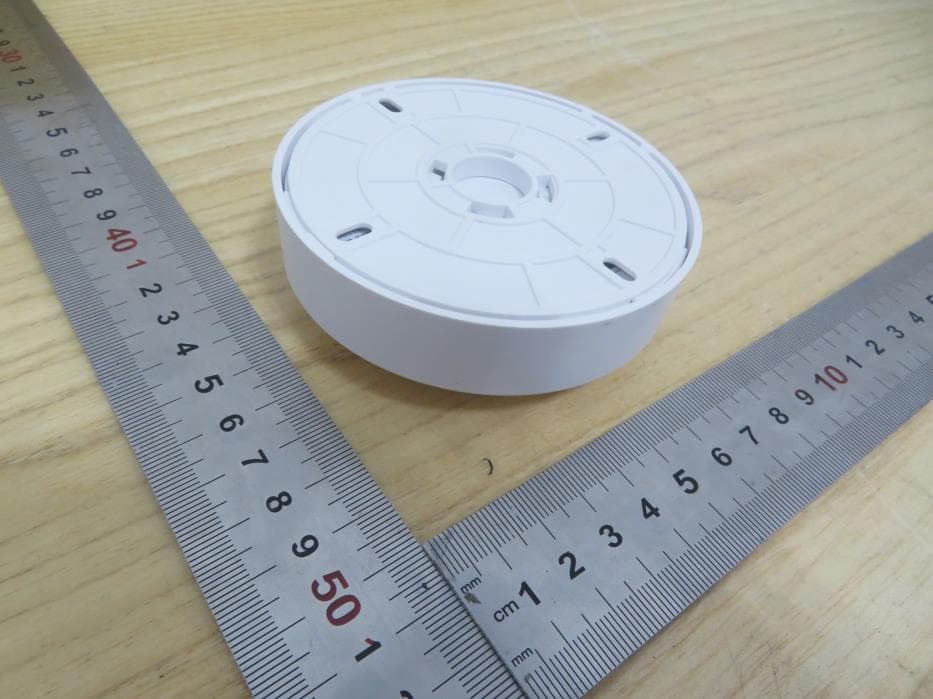
2AS3F-WOS3PC
Mar 17, 2022Smart Sensor
Equipment Class
DTS - Digital Transmission System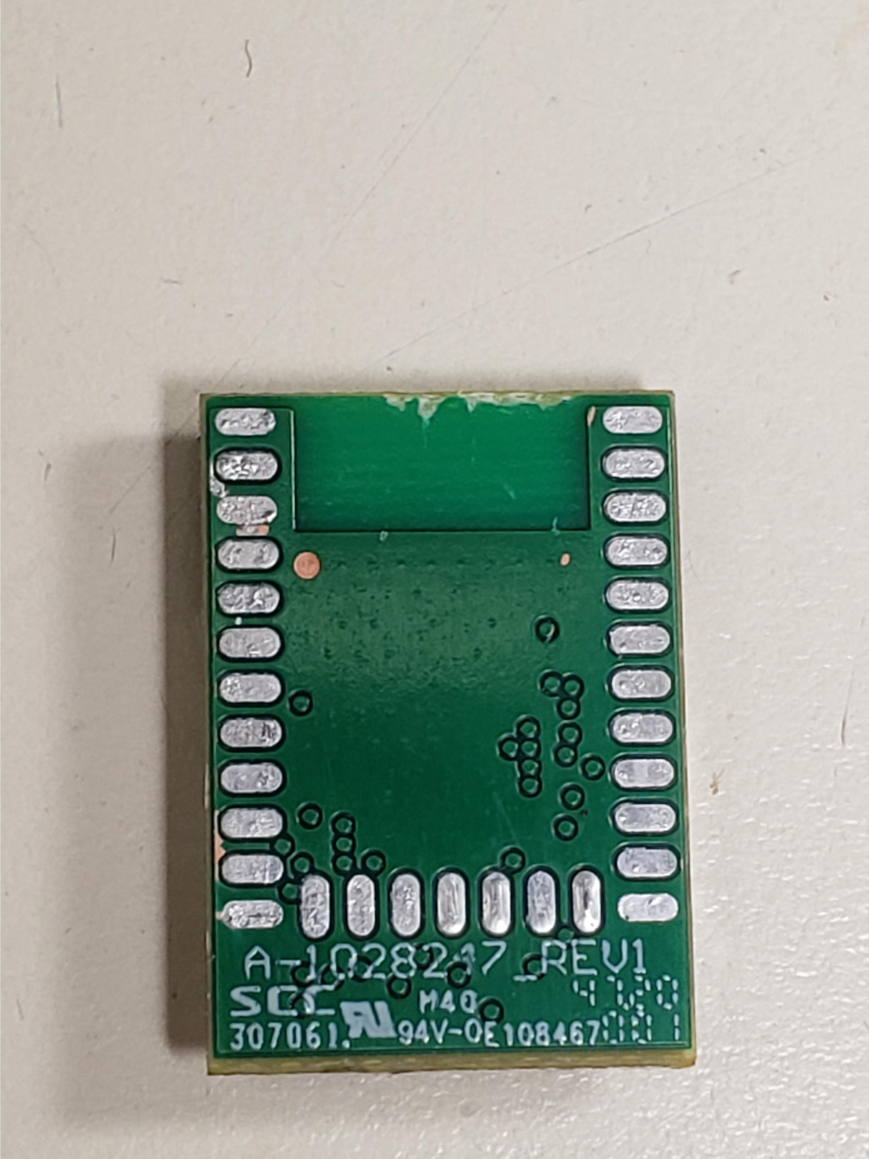
2AS3F-A1028250
Jul 08, 2021RF Module, 2400-2483.5 MHz
Equipment Class
DTS - Digital Transmission System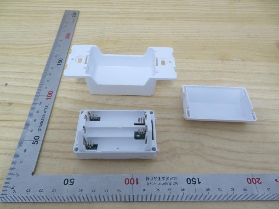
2AS3F-WWD2IW
Apr 10, 2021Wireless Wall Dimmer
Equipment Class
DTS - Digital Transmission System