2ASAF-PLUGPRO03Wi-Fi Plug Pro
Shenzhen Eybond Co., Ltd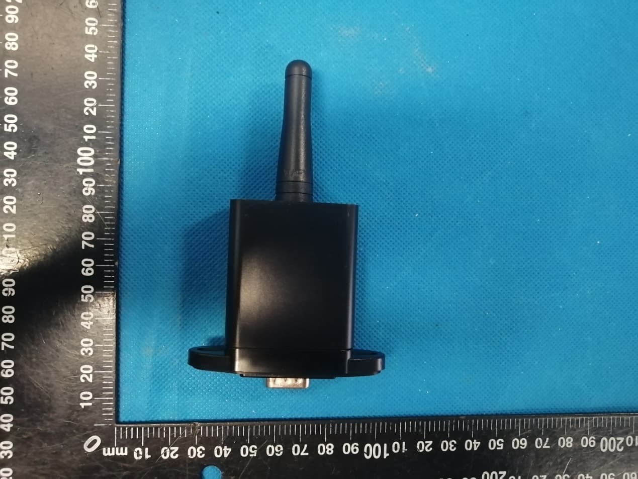
Click to zoom
Application Details
- Equipment Class
- DTS - Digital Transmission System
- Date of Grant
- Aug 30, 2020
- Application Purpose
- Original Equipment
- Date of Application
- Aug 30, 2020
- Equipment Note
- Wi-Fi Plug Pro
- Frequency Range
- 2412.00000000 - 2462.00000000
- Company
- Shenzhen Eybond Co., Ltd
- Country
- China
Documents & Files
Document Text
Text extracted from the exhibit documents filed with the FCC. Open a document above to read the original.
Users Manual
PWR CCM NET SRV PWR CCM NET SRV PWR CCM NET SRV PWR CCM NET SRV 快速安装指南 小蜜蜂(Wi-Fi版)数采器 护光者 记住密码 请输入用户名 请输入密码 登录 Wi-Fi配置 注册 示例电站 > ① 扫描右方的二维码,下载APP。 ① 打开APP,点击“Wi-Fi配置”按钮, 进入“Wi-Fi配置”页面。 ② 在“Wi-Fi配置”页面,点击“连接 Wi-Fi数采器”按钮(安卓手机不需 此步骤)。 ③ 找到与数采器PN号相同的Wi-Fi 进行连接(初始密码:12345678)。 Wi-Fi连接 选取无线网络... W2015 2018LA 无线局域网 Eybond 2.4g Eybond2015 W0016250020617 Wifi111 Wifi-test 请输入无线密码 12345678 ① 点击“连网设置”按钮,进入该界面。 ② 填写相关信息,完成连网设置。 ③ 断开2.2步骤所连接的数采器Wi-Fi 。 ④ 重新连接可上网的Wi-Fi热点或运营商网络。 连网设置 路由器: 密码: 请输入路由器的SSID 请输入路由器的密码 请与无线路由器进行连接,确保远程数据传输 设置 确认密码: 请确认路由器的密码 护光者 记住密码 请输入用户名 请输入密码 登录 Wi-Fi配置 注册 示例电站 > 注册 用户名 密码 确认密码 邮箱地址 手机号码 采集器编码 完成 PN号 ① 在APP首页,点击“注册”按钮, 按提示填写相关信息,完成注册。 创建电站 请输入电站名称 电站名称* 完成 电站描述 电站图片 请输入电站描述 电站图片 ① 登录APP,选择“列表”菜单。 ② 点击右上角的“+”按钮,进入 到“创建电站”页面。 ③ 根据提示输入相关信息,完成电 站创建。 ① 点击已经建好的电站,进入该电站 主界面。 ② 选择“设备”菜单,点击右上 角的 “+”按钮,进入到“添加数采器” 页面。 ③ 扫描数采器的PN号,添加数采器; 如果扫描不成功,可以手动输入。 注意:一个账号可创建多个电站,一个电站可添加多个数采器,若您只有一个数采器,则不需此步骤。 电站名称 当前功率:55.6kW 日发电量:141.6kWh 当日收益:¥158.2 364.3kWh 总览 列表 地图 我的 新建电站 新建电站 您还没有电站, 请添加电站! 总览 列表 地图 我的 手动输入数采器PN号 添加数采器 数采器上的PN号 添加设备 设备类型 设备名称 当前功率:12.5kW 日发电量:12.5kWh 设备 P N:123456789 信息 地图 数据 告警 设备 Android iOS 未连接Wi-Fi 请选择一个Wi-Fi数采器并与其连接 Wi-Fi配置 连接Wi-Fi数采器 连网诊断 连网设置 请选择一个Wi-Fi数采器并与其连接 Wi-Fi配置 连接Wi-Fi数采器 连网诊断 连网设置 W0016250020617 ❶ ❷ ❸ ❹ Wi-Fi PlugII - 03/05/06/08/12/13 数采器型号 接口编码 接口图例 Wi-Fi PlugII - 07 Wi-Fi PlugII - 02/10 Wi-Fi PlugII - 01/11(方案1) Wi-Fi PlugII - 04(方案2) 电气连接 1. ❶ 方案1: ① 将数采器的4PIN电源线与逆变器4PIN 端子对接。 ② 用螺丝把数采器固定在逆变器上。 方案2: ① 将数采器的2PIN绿色接头与逆变器的 RS-485端子对接。 ② 将数采器的5PIN电源线与逆变器5PIN 端子对接。 ③ 用螺丝把数采器固定在逆变器上。 ① 将数采器的4孔航空接头与逆变器的航 空接口对齐,插紧。 ② 将数采器的螺帽与逆变器的螺杆拧紧。 ① 将数采器的RJ-45水晶头与逆变器的 RJ-45母插座对齐,插紧。 ② 用螺丝把数采器固定在逆变器上。 ① 将数采器的串口与逆变器的串口对齐, 插紧。 ② 用螺丝把数采器固定在逆变器上。 ① 根据数采器型号在右方找到对应 的接口编码。 ② 根据接口编码按照对应图示进行 电气连接。 ③ 确认数采器各指示灯状态正常 (步骤2.3连网设置成功后,四灯 常亮为正常)。 ❷ ❸ ❹ 无线路由器连接 2. 2.1 APP下载 2.2 Wi-Fi数采器连接 2.3 连网参数设置 注册账号与创建电站 3. 3.1 账号注册 3.2 电站创建 3.3 添加多个数采器 确定电站位置 当前位置:深圳市宝安区 请输入你要创建的电站位置 确定 取消 PWR CCM NET SRV Quick Installation Guideline Wi-Fi PlugII PWR CCM NET SRV PWR CCM NET SRV PWR CCM NET SRV ① Open the APP, tap the Wi-Fi Config button to enter this page. ② Tap the Connect Wi-Fi Datalogger button on the Connected page (Android phone has no need of this step) . ③ Select the same number of Wi-Fi PlugII PN to connect. (Initial Password: 12345678) ① After the connection completes, tap the Network Setting button. ② According to the prompts, type in the information to finish the network setting. ③ Reconnect the Wi-Fi or Cellular Data which can surf the Internet instead of the Wi-Fi connected by step 2.2. ① Scan the QR Code on the right side and download the APP. 2.1 Download APP WLAN CHOOSE A NETWORK... W2015 2018LA WLAN Eybond 2.4g Eybond2015 W0016250020617 Wifi111 Wifi-test PASSWORD 12345678 Disconnect Please choose a Wi-Fi and connect. Connected Connect Wi-Fi Datalogger Network Diagnose Network Setting SmartClient Keep password Please enter user name Please enter password Login Wi-Fi Config Register DEMO> Network Settings Router Name: Password: Please connect to the wireless router Setting Confirm password: Register User Name Password Confirm Password E-mail Phone Number PN Register Datalogger PN ① Open the APP, tap the Register button to enter this page. ② According to the prompts, type in the information to create an account. ① Login the account and click the list button on the bottom of the home page. ② Tap the “+” button on the top- right corner of the list page ③ According to the prompts, type in the information to finish creating plant. 3.3 Add Multiple Dataloggers ① Tap the new plant you just created, and enter its home page. ② Click the Device button on the bottom of the home page. ③ Tap the “+” button at the top-right corner to add the datalogger. ④ Scan the datalogger PN on the Wi-Fi PlugII, or input it manually. Note: One account can create multiple plants and one plant can add multiple dataloggers. If you only have one datalogger, you could ignore this step. 新建电站 SmartClient Keep password Please enter user name Please enter password Login Wi-Fi Config Register Demo> Create Plants Please enter plant’s name Plant Name* Finish Plant description Plant picture Please input the description the plant Plant picture 3.2 Create Plant 3.1 Create Account Installation 1. W0016250020617 Please choose a Wi-Fi and connect. Connected Network Diagnose Network Setting Connect Wi-Fi Datalogger Plant Name Current power: 55.6kW Daily generation: 141.6kWh Daily income: ¥158.2 Total generation: 364.3kWh OVERVIEW LIST MAP ME Input the Datalogger PN Datalogger PN Add Datalogger Add Datalogger Device Device 1 Current power: 125kW Daily generation: 125kWh PN:123456789 Info Map Data Alarm Devices 2.3 Network Setting 2.2 Connect Wi-Fi Datalogger Android iOS Wireless Router Connection 2. Create Account And Plant 3. ❶ ❷ ❸ ❹ ① Find the corresponding interface code on the right table, according to the model of the datalogger. ② Based on the corresponding icon, finish the installation according to the interface code. ③ Confirm the status of the LED light (After step2.3, when 4 LED light keep on, showing the normal working status). Wi-Fi PlugII - 03/05/06/08/12/13 Datalogger Model Interface Code Interface Icon Wi-Fi PlugII - 07 Wi-Fi PlugII - 02/10 Wi-Fi PlugII - 01/11(Method 1) Wi-Fi PlugII - 04(Method 2) ❶ Method 1 : ① Connect the 4PIN power cable of the Wi-Fi PlugII to the inverter. ② Fasten the Wi-Fi PlugII to the inverter with the screw. Method 2 : ① Connect the 2 PIN green interface of the Wi-Fi PlugII to the RS-485 terminal of the inverter. ② Connect the 5PIN power cable of the Wi-Fi PlugII to the inverter. ③ Fasten the Wi-Fi PlugII to the inverter with the screw. ① Align the 4-hole aviation plug of the Wi-Fi PlugII with the inverter and plug it in. ② Tighten the nut of the Wi-Fi PlugII to the inverter. ❷ ① Align the RJ-45 crystal head of the Wi-Fi PlugII with the inverter and insert it in tightly. ② Fasten the Wi-Fi PlugII to the inverter with the screw. ❸ ① Align the serial port of the Wi-Fi PlugII with the invert…
Text truncated - open the document above for the full version.
Cover Letter(s)
Shenzhen Eybond Co., Ltd Agent Authorization Company: Shenzhen Eybond Co., Ltd Address: Building 10, Zhiheng Science &Technology Park, Nantou Street, Nanshan District, Shenzhen City, Guangdong Province, China Product Name: Wi-Fi Plug Pro Model Number(s ): Wi-Fi Plug Pro-03 Product Description: Wi-Fi Plug Pro We authorize MiCOM Labs Inc., 575 Boulder Court, Pleasanton, California 94566, USA, to act on our behalf on all matters concerning the certification of above named equipment. We declare that MiCOM Labs Inc. is allowed to forward all information related to the approval and certification of equipment to the regulatory agencies as required and to discuss any issues concerning the approval application. Any and all acts carried out by MiCOM Labs on our behalf shall have the same effect as acts of our own. Signature: Date: Aug. 17, 2020 Name: Mencius meng Title: Manager Company: Shenzhen Eybond Co., Ltd
Cover Letter(s)
Shenzhen Eybond Co., Ltd Office of Engineering Technology Federal Communications Commission 7435 Oakland Mills Road Columbia, MD 21046 USA Date: Aug. 17, 2020 Subject; Request for Confidentiality FCC ID: 2ASAF-PLUGPRO03 To Whom It May Concern, Pursuant to the provisions of the Commission’s rules Title 47 Sections §0.457 and §0.459, we are requesting the Commission to withhold the following attachment(s) as confidential documents from public disclosure indefinitely. These documents contain detailed system and equipment descriptions and are considered as proprietary information in operation of the equipment. The public disclosure of these documents might be harmful to our company and would give competitors an unfair advantage in the market. Schematic Diagram Block Diagram Parts List Operational Description Tune-up Procedure It is our understanding that all measurement test reports, FCC ID label format and correspondence during the certification review process cannot be granted as confidential documents and this information will be available for public review once the grant of equipment authorization is issued. Sincerely, Signature: Name: Mencius meng Title: Manager
External Photos
Annex A External Photos Report No.: HK2007202172-E Page 1 of 3 Report No.: HK2007202172-E Page 2 of 3 Report No.: HK2007202172-E Page 3 of 3
ID Label/Location Info
FCC ID LABEL: Ca. 5mm x 10mm Include in manual: This device complies with part 15 of the FCC Rules. Operation is subject to the following two conditions: (1) This device may not cause harmful interference, and (2) this device must accept any interference received, including interference that may cause undesired operation. Label Location FCC ID: 2ASAF-PLUGPRO03
Internal Photos
Annex B Internal Photos Report No.: HK2007202172-E Page 1 of 4 2.4g WiFi Antenna Report No.: HK2007202172-E Page 2 of 4 Report No.: HK2007202172-E Page 3 of 4 Report No.: HK2007202172-E Page 4 of 4
RF Exposure Info
MPE ESTIMATION FCC ID: 2ASAF-PLUGPRO03 1,Limit for General Population/ Uncontrolled Exposures Frequency Power density (mW/ cm 2 ) Averaging time(minutes) 300MHz----1.5GHz F/1500 30 1.5GHz---100GHz 1.0 30 Note: F= Frequency in MHz 2, Estimation Result 2.4G WIFI Mode Frequency (MHz) Max PK Output power(dBm) Tune Up Power(dBm) Max Tune Up power(mW) Antenna Gain(dBi) Antenna Gain (linear) MPE ( mW/cm²) WiFi 2412 19.32 19±1(20) 100.00 0 1.0000 0.01989 Note: Note: The estimation distance is 20cm Note: PK Output power= conducted power. Conducted power see the test report HK2007202172-E, antenna gain=0dBi when the minimum test separation distance is >20 cm, a distance of 20 cm is applied to determine RF Exposure test exclusion. The test exclusion threshold is 0.01989 mW/cm² which is< 1.0mW/cm², RF Exposure testing is not required. -------The End-------
Test Report
Report No.: HK2007202172-E FCC TEST REPORT Test report On Behalf of Shenzhen Eybond Co., Ltd For Wi-Fi Plug Pro Model No.: Wi-Fi Plug Pro-03 FCC ID: 2ASAF-PLUGPRO03 Prepared for : Shenzhen Eybond Co., Ltd Building 10, Zhiheng Science &Technology Park, Nantou Street, Nanshan District, Shenzhen City, Guangdong Province, China Prepared By : Shenzhen HUAK Testing Technology Co., Ltd. 1F, B2 Building, JunfengZhongchengZhizao Innovation Park, Fuhai Street, Bao'an District, Shenzhen City, China Date of Test: Jul. 23, 2020 ~ Aug. 13, 2020 Date of Report: Aug. 13, 2020 Report Number: HK2007202172-E Report No.: HK2007202172-E Page 2 of 58 TEST RESULT CERTIFICATION Applicant’s name .................. : Shenzhen Eybond Co., Ltd Address .................................. : Building 10, Zhiheng Science &Technology Park, Nantou Street, Nanshan District, Shenzhen City, Guangdong Province, China Manufacture's Name ............ : Shenzhen Eybond Co., Ltd Address .................................. : Building 10, Zhiheng Science &Technology Park, Nantou Street, Nanshan District, Shenzhen City, Guangdong Province, China Product description Trade Mark: Eybond Product name ............................ : Wi-Fi Plug Pro Model and/or type reference : Wi-Fi Plug Pro-03 Standards .............................. : FCC Rules and Regulations Part 15 Subpart C Section 15.247 ANSI C63.10: 2013 This publication may be reproduced in whole or in part for non-commercial purposes as long as the Shenzhen HUAK Testing Technology Co., Ltd. is acknowledged as copyright owner and source of the material. Shenzhen HUAK Testing Technology Co., Ltd. takes no responsibility for and will not assume liability for damages resulting from the reader's interpretation of the reproduced material due to its placement and context. Date of Test ............................................ : Date (s) of performance of tests ............. : Jul. 23, 2020 ~ Aug. 13, 2020 Date of Issue .......................................... : Aug. 13, 2020 Test Result .............................................. : Pass Testing Engineer : (Gary Qian) Technical Manager : (Eden Hu) Authorized Signatory : (Jason Zhou) Report No.: HK2007202172-E Page 3 of 58 TABLE OF CONTENTS 1. Test Result Summary ............................................................................... 5 1.1. TEST PROCEDURES AND RESULTS ............................................................................................... 5 1.2. TEST FACILITY .................................................................................................................................. 5 1.3. MEASUREMENT UNCERTAINTY ............................................................................................................... 6 2. EUT Description ........................................................................................ 7 2.1. GENERAL DESCRIPTION OF EUT ................................................................................................... 7 2.2. CARRIER FREQUENCY OF CHANNELS ..................................................................................................... 8 2.3. OPERATION OF EUT DURING TESTING .................................................................................................... 8 2.4. DESCRIPTION OF TEST SETUP ....................................................................................................... 9 3. Genera Information ................................................................................. 10 3.1. TEST ENVIRONMENT AND MODE ............................................................................................................ 10 3.2. DESCRIPTION OF SUPPORT UNITS ........................................................................................................ 11 4. Test Results and Measurement Data .................................................... 12 4.1. CONDUCTED EMISSION ........................................................................................................................ 12 4.2. TEST RESULT ...................................................................................................................................... 14 4.3. MAXIMUM CONDUCTED OUTPUT POWER .............................................................................................. 15 4.4. EMISSION BANDWIDTH ......................................................................................................................... 17 4.5. POWER SPECTRAL DENSITY ................................................................................................................ 22 4.6. CONDUCTED BAND EDGE AND SPURIOUS EMISSION MEASUREMENT ..................................................... 27 4.7. RADIATED SPURIOUS EMISSION MEASUREMENT ................................................................................... 35 4.8. ANTENNA REQUIREMENT ............................................................................................................. 56 4.9. PHOTOGRAPH OF TEST ................................................................................................................. 57 4.10. PHOTOS OF THE EUT ..................................................................................................................... 58 Report No.: HK2007202172-E Page 4 of 58 ** Modifited History ** Revison Description Issued Data Remark Revsion 1.0 Initial Test Report Release 2020/08/13 Jason Zhou Report No.: HK2007202172-E Page 5 of 58 1. Test Result Summary 1.1. TEST PROCEDURES AND RESULTS Requirement CFR 47 Section Result Antenna requirement §15.203/§15.247 (c) PASS AC Power Line Conducted Emission §15.207 N/A Conducted Peak Output Power §15.247 (b)(3) PASS 6dB Emission Bandwidth §15.247 (a)(2) PASS Power Spectral Density §15.247 (e) PASS Band Edge 1§5.247(d) PASS Spurious Emission §15.205/§15.209 PASS Note: 1. PASS: Test item meets the requirement. 2. Fail: Test item does not meet the requirement. 3. N/A:…
Text truncated - open the document above for the full version.
Test Setup Photos
Test Model:Wi-Fi Plug Pro-03 Radiated Emission
Contact Information
Applicant
Mencius meng
Technical Contact
Test Firm
Shenzhen HUAK Testing Technology Co., Ltd.Jason Zhou
[email protected]+86-755-23029901
Technical Specifications
| # | Rule Parts | Frequency Range | Power Output |
|---|---|---|---|
| 1 | 15C | 2.41 GHz - 2.46 GHz | 85.51 mW |
Other Applications from Shenzhen Eybond Co., Ltd
2ASAF-WFBLE
Mar 12, 2026Module
Equipment Class
DTS - Digital Transmission System
2ASAF-07C
Jan 28, 2026Datalogger
Equipment Class
DTS - Digital Transmission System
2ASAF-MODULE-106
Jan 15, 2026Module
Equipment Class
DTS - Digital Transmission System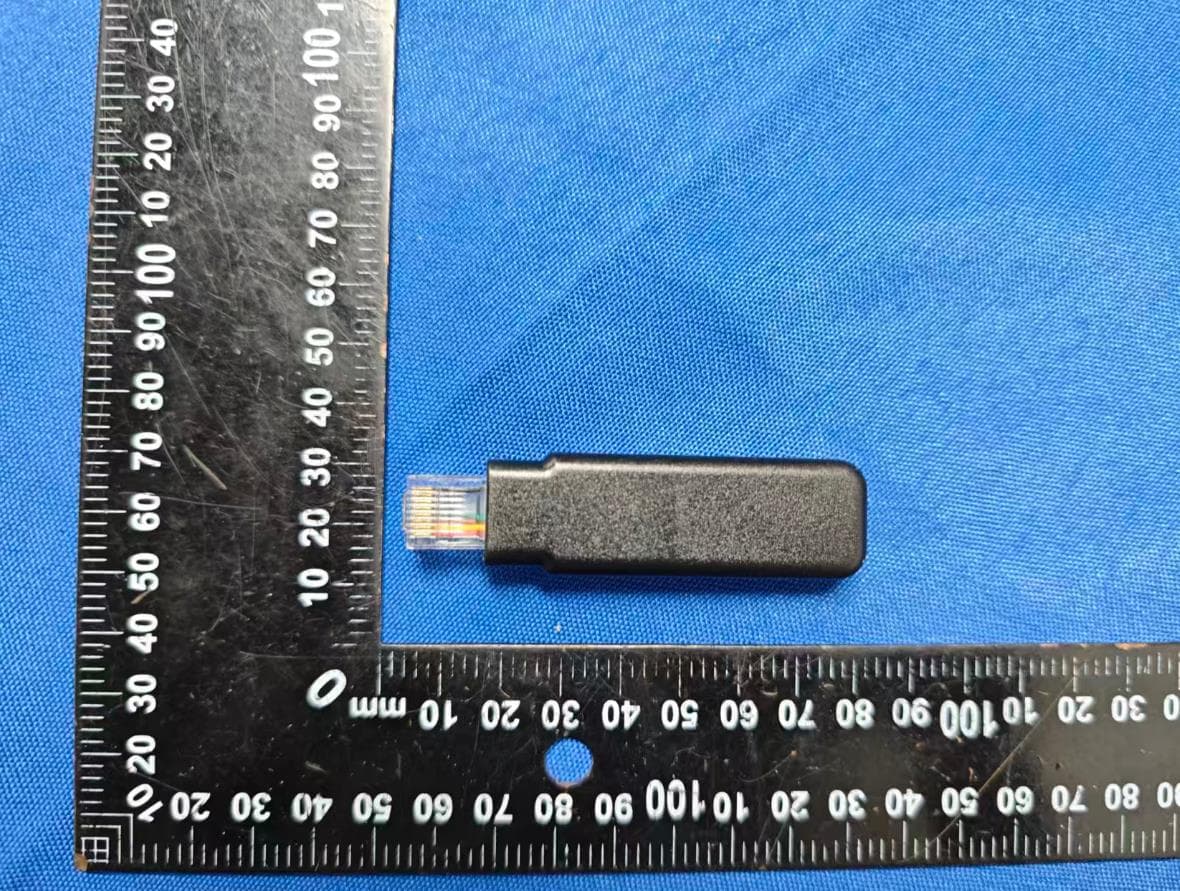
2ASAF-BAR-06F
Dec 05, 2025Datalogger
Equipment Class
DTS - Digital Transmission System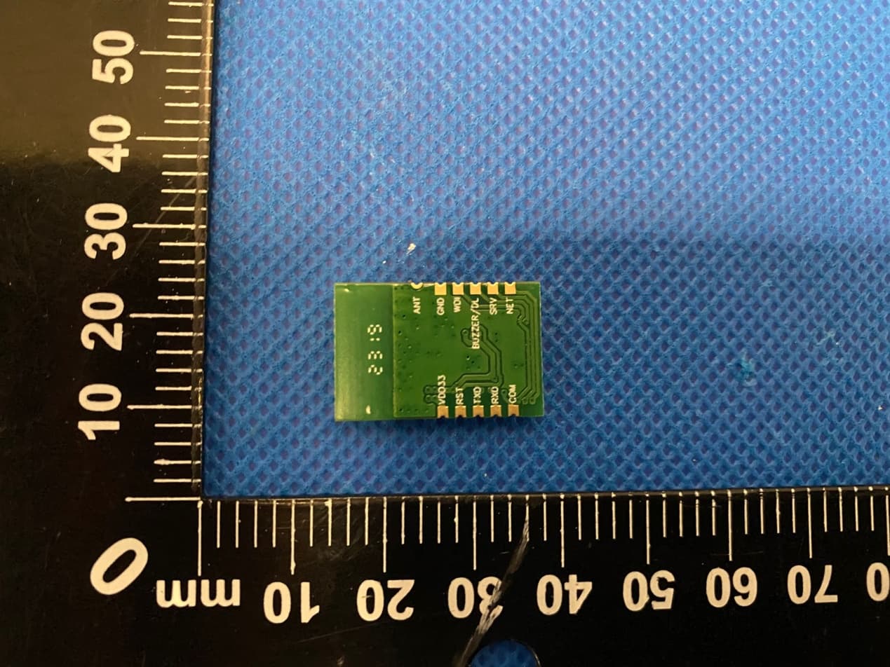
2ASAF-MODULE201
Jul 01, 2023WFBLE.Module
Equipment Class
DTS - Digital Transmission System