2ASC7FX9000Professional Diagnostic Tool
OBDSPACE TECHNOLOGY CO,.LTD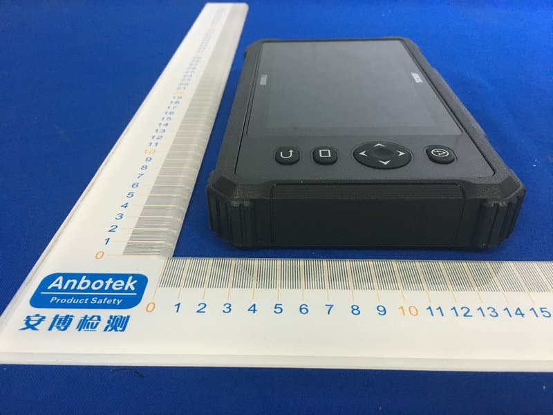
Click to zoom
Application Details
- Equipment Class
- DTS - Digital Transmission System
- Date of Grant
- Aug 12, 2020
- Application Purpose
- Original Equipment
- Date of Application
- Aug 12, 2020
- Equipment Note
- Professional Diagnostic Tool
- Frequency Range
- 2412.00000000 - 2462.00000000
- Company
- OBDSPACE TECHNOLOGY CO,.LTD
- Country
- China
Documents & Files
Document Text
Text extracted from the exhibit documents filed with the FCC. Open a document above to read the original.
Users Manual
i LAUNCH Gear Scan Plus User Manual EN Copyright Information Copyright © 2019 by LAUNCH TECH CO., LTD. All rights reserved. No part of this publication may be reproduced, stored in a retrieval system, or transmitted in any form or by any means, electronic, mechanical, photocopying and recording or otherwise, without the prior written permission of LAUNCH. The information contained herein is designed only for the use of this unit. LAUNCH is not responsible for any use of this information as applied to other units. Statement: LAUNCH owns the complete intellectual property rights for the software used by this product. For any reverse engineering or cracking actions against the software, LAUNCH will block the use of this product and reserve the right to pursue their legal liabilities. Trademark Information LAUNCH is a registered trademark of LAUNCH TECH CO., LTD. (also called LAUNCH for short) in China and other countries. All other LAUNCH trademarks, service marks, domain names, logos, and company names referred to in this manual are either trademarks, registered trademarks, service marks, domain names, logos, company names of or are otherwise the property of LAUNCH or its affiliates. In countries where any of the LAUNCH trademarks, service marks, domain names, logos and company names are not registered, LAUNCH claims other rights associated with unregistered trademarks, service marks, domain names, logos, and company names. Other products or company names referred to in this manual may be trademarks of their respective owners. You may not use any trademark, service mark, domain name, logo, or company name of LAUNCH or any third party without permission from the owner of the applicable trademark, service mark, domain name, logo, or company name. You may contact LAUNCH by visiting the website at www.cnlaunch.com, or writing to LAUNCH TECH CO., LTD., Launch Industrial Park, North of Wuhe Avenue, Banxuegang, Bantian, Longgang, Shenzhen, Guangdong, P.R.China, to request written permission to use Materials on this manual for purposes or for all other questions relating to this manual. ii LAUNCH Gear Scan Plus User Manual General Notice • Other product names used herein are for identification purposes only and may be trademarks of their respective owners. LAUNCH disclaims any and all rights in those marks. • There is a possibility that this unit is inapplicable to some of the vehicle models or systems listed in the diagnosis section due to different countries, areas, and/or years. Do not hesitate to contact LAUNCH if you come across such questions. We are to help you solve the problem as soon as possible. Disclaimer • To take full advantage of the unit, you should be familiar with the engine. • All information, illustrations, and specifications contained in this manual are based on the latest information available at the time of publication. The right is reserved to make change at any time without notice. • Neither LAUNCH nor its affiliates shall be liable to the purchaser of this unit or third parties for damages, losses, costs or expenses incurred by purchaser or third parties as a result of: accident, misuse, or abuse of this unit, or unauthorized modifications, repairs, or alterations to this unit, or failure to strictly comply with LAUNCH operating and maintenance instructions. • LAUNCH shall not be liable for any damages or problems arising from the use of any options or any consumable products other than those designated as Original LAUNCH Products or LAUNCH Approved Products by LAUNCH. Safety Precautions and Warnings To prevent personal injury or damage to vehicles and/or this tool, please read this user’s manual first carefully and observe the following safety precautions at a minimum whenever working on a vehicle: • Always perform automotive testing in a safe environment. • Do not attempt to operate or observe the tool while driving a vehicle. Operating or observing the tool will cause driver distraction and could cause a fatal accident. • Wear safety eye protection that meets ANSI standards. • Keep clothing, hair, hands, tools, test equipment, etc. away from all moving or hot engine parts. • Operate the vehicle in a well-ventilated work area: Exhaust gases are poisonous. • Put blocks in front of the drive wheels and never leave the vehicle unattended while running tests. iii LAUNCHGear Scan Plus User Manual EN •Use extreme caution when working around the ignition coil, distributor cap, ignition wires and spark plugs. These components create hazardous voltages when the engine is running. •Put the transmission in P (for A/T) or N (for M/T) and make sure the parking brake is engaged. •Keep a fire extinguisher suitable for gasoline/chemical/ electrical fires nearby. •Don’t connect or disconnect any test equipment while the ignition is on or the engine is running. •Keep this tool dry, clean, free from oil/water or grease. Use a mild detergent on a clean cloth to clean the outside of the tool, when necessary. •Please use the DC 5V power adaptor to charge this tool. No responsibility can be assumed for any damage or loss caused as a result of using power adaptors other than the right one. iv LAUNCH Gear Scan Plus User Manual Table of Contents 1. Introduction ..............................................................................................1 2. General Information ................................................................................2 2.1 On-Board Diagnostics (OBD) II ......................................................................2 2.2 Diagnostic Trouble Codes (DTCs) ..................................................................2 2.3 Location of the Data Link Connector (DLC)....................................................3 2.4 OBD II Readiness Monitors ............................................................................4 2.5 OBD II Monitor Readiness Status...................................................................5 2.6 OBD II Definitions ...…
Text truncated - open the document above for the full version.
External Photos
FCC ID: 2ASC7FX9000
ID Label/Location Info
Label Location On EUT Label Product Name: Professional Diagnostic Tool Model No.: FX9000 FCC ID: 2ASC7FX9000 This device complies with Part 15 of the FCC Rules. Operation is subject to the following two conditions: (1) This device may not cause harmful interference, and (2)This device must accept any interference received, including interference that may cause undesired operation.
Internal Photos
FCC ID: 2ASC7FX9000 ANT
Operational Description
version01 OBDSPACETECHNOLOGYCO,.LTD Declaration concerning Antenna Specification It is hereby declared that the product Model No.: FX9000 FCC ID : 2ASC7FX9000 fulfills the requirement in FCC test relating to the antenna type. The device specified above confirms to the FCC recommendations for internal antenna type(s) described below: Model No. of antenna: BYS006-WIFI-KYX-181121 Type of antenna:PIFA Antenna Gain of the antenna: 1.77 dBi Frequency range:2412-2462MHz The mounting of the antenna is fixed to the radio module and no other antenna should be used. Company name: OBDSPACE TECHNOLOGY CO,.LTD Address: Room D03, Building A, No.973, MinZhi Avenue LongHua district, Shenzhen City, China City:Shenzhen ZIP / Postal code: N/A Country:China Place:ChinaDate: 2020-08-11 Signature:
RF Exposure Info
Report No.: 18220WC00098002FCC ID: 2ASC7FX9000Page 1 of 64 FCC SAR Test Report Client Name:OBDSPACE TECHNOLOGY CO,.LTD Address: Room D03, Building A, No.973, MinZhi Avenue LongHua district, Shenzhen City, China Product Name:Professional Diagnostic Tool Date:Aug. 10, 2020 Shenzhen Anbotek Compliance Laboratory Limited Report No.: 18220WC00098002FCC ID: 2ASC7FX9000Page 2 of 64 Contents 1. Statement of Compliance .............................................................................................................. 6 2. General Information ........................................................................................................................ 7 2.1Client Information .......................................................................................................................................................................... 7 2.2Description of Equipment Under Test (EUT) ............................................................................................................................ 7 2.3Device Category and SAR Limits ............................................................................................................................................... 8 2.4Applied Standard ........................................................................................................................................................................... 8 2.5Environment of Test Site .............................................................................................................................................................. 8 2.6Test Configuration ......................................................................................................................................................................... 8 3. Specific Absorption Rate (SAR) ................................................................................................... 9 3.1Introduction ..................................................................................................................................................................................... 9 3.2SAR Definition ................................................................................................................................................................................ 9 4. SAR Measurement System ......................................................................................................... 10 4.1E-Field Probe ............................................................................................................................................................................... 11 4.2Data Acquisition Electronics (DAE) .......................................................................................................................................... 11 4.3Robot ............................................................................................................................................................................................. 12 4.4Measurement Server .................................................................................................................................................................. 13 4.5Phantom ........................................................................................................................................................................................ 13 4.6Device Holder .............................................................................................................................................................................. 15 4.7Data Storage and Evaluation .................................................................................................................................................... 16 5. Test Equipment List ...................................................................................................................... 18 6. Tissue Simulating Liquids ............................................................................................................ 19 7. System Verification Procedures ................................................................................................. 21 8. EUT Testing Position ................................................................................................................... 23 8.1Body Worn Position .................................................................................................................................................................... 23 9. Measurement Procedures ........................................................................................................... 24 9.1Spatial Peak SAR Evaluation ................................................................................................................................................... 24 9.2Power Reference Measurement .............................................................................................................................................. 25 9.3Area Scan Procedures ............................................................................................................................................................... 25 9.4Zoom Scan Procedures ............................................................................................................................................................. 26 9.5Volume Scan Procedures .......................................................................................................................................................... 27 9.6Power Drift Monitoring ................................................................................................................................................................ 27 10. Conducted Power ....................................................................................................................... 28 11. Antenna Location.................................…
Text truncated - open the document above for the full version.
Test Report
Report No.: 18220WC00098001FCC ID: 2ASC7FX9000Page 1 of 70 Code:AB-RF-05-a FCC TEST REPORT Client Name: OBDSPACE TECHNOLOGY CO,.LTD Address: Room D03, Building A, No.973, MinZhi Avenue LongHua district, Shenzhen City, China Product Name: Professional Diagnostic Tool Date: Aug. 10, 2020 Shenzhen Anbotek Compliance Laboratory Limited Report No.: 18220WC00098001FCC ID: 2ASC7FX9000Page 2 of 70 Code:AB-RF-05-a Contents 1. General Information ............................................................................................................................................... 5 1.1. Client Information ....................................................................................................................................... 5 1.2. Description of Device (EUT) ..................................................................................................................... 5 1.3. Auxiliary Equipment Used During Test ................................................................................................... 5 1.4. Description of Test Modes ........................................................................................................................ 6 1.5. List of channels ........................................................................................................................................... 7 1.6. Description Of Test Setup ......................................................................................................................... 8 1.7. Test Equipment List .................................................................................................................................... 9 1.8. Measurement Uncertainty ....................................................................................................................... 10 1.9. Description of Test Facility ...................................................................................................................... 10 2. Summary of Test Results ................................................................................................................................... 11 3. Conducted Emission Test ................................................................................................................................... 12 3.1. Test Standard and Limit .......................................................................................................................... 12 3.2. Test Setup .................................................................................................................................................. 12 3.3. Test Procedure .......................................................................................................................................... 12 4. Radiation Spurious Emission and Band Edge ................................................................................................ 17 4.1. Test Standard and Limit .......................................................................................................................... 17 4.2. Test Setup .................................................................................................................................................. 17 4.3. Test Procedure .......................................................................................................................................... 18 4.4. Test Data .................................................................................................................................................... 19 5. Maximum Peak Output Power Test .................................................................................................................. 29 5.1. Test Standard and Limit .......................................................................................................................... 29 5.2. Test Setup .................................................................................................................................................. 29 5.3. Test Procedure .......................................................................................................................................... 29 5.4. Test Data .................................................................................................................................................... 29 6. 6DB Occupy Bandwidth Test ............................................................................................................................. 33 6.1. Test Standard and Limit .......................................................................................................................... 33 6.2. Test Setup .................................................................................................................................................. 33 6.3. Test Procedure ............................................................................................................................... ........... 33 6.4. Test Data .................................................................................................................................................... 33 7. Power Spectral Density Test .............................................................................................................................. 41 7.1. Test Standard and Limit .......................................................................................................................... 41 7.2. Test Setup .................................................................................................................................................. 41 7.3. Test Procedure .......................................................................................................................................... 41 7.4. Test Data .............................................................................................................................................…
Text truncated - open the document above for the full version.
Test Setup Photos
FCC ID: 2ASC7FX9000 Photo of Conducted Emission Measurement Photo of Radiation Emission Test
Contact Information
Applicant
Frank Hao(Manager)
Test Firm
Shenzhen Anbotek Compliance Laboratory LimitedJeff Zhu
Technical Specifications
| # | Rule Parts | Frequency Range | Power Output |
|---|---|---|---|
| 1 | 15C | 2.41 GHz - 2.46 GHz | 70.80 mW |
Other Applications from OBDSPACE TECHNOLOGY CO,.LTD

2ASC7-X6
Jan 30, 2025Automotive OBD2 Scanner Diagnostic Tool
Equipment Class
DSS - Part 15 Spread Spectrum Transmitter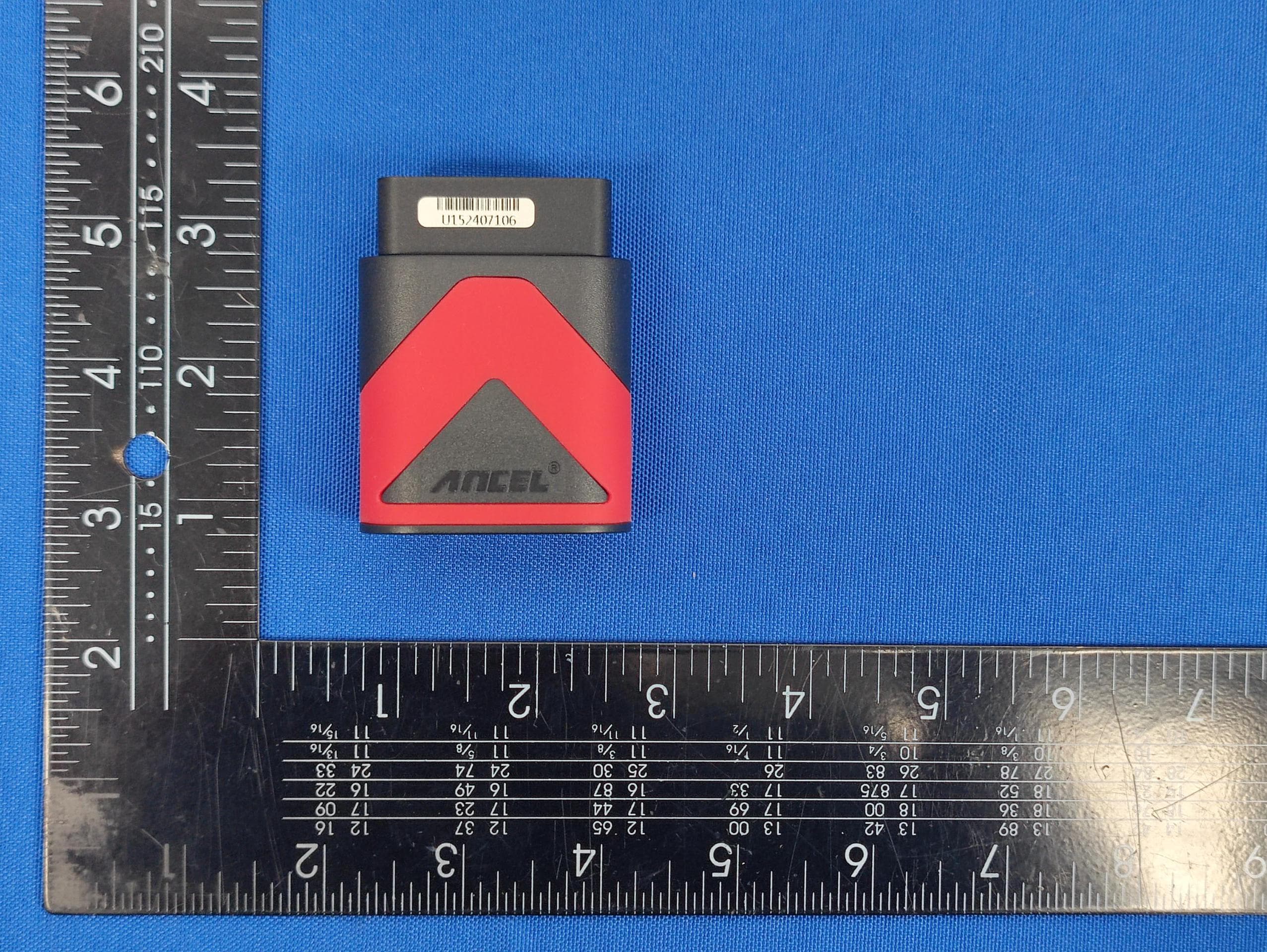
2ASC7VCIU15
Oct 13, 2024VCI U1
Equipment Class
DTS - Digital Transmission System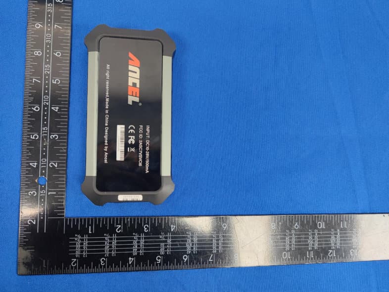
2ASC7VCIU18
Oct 13, 2024VCI T6
Equipment Class
DTS - Digital Transmission System
2ASC7-HD43X
Jul 06, 2024Truck Scanner
Equipment Class
DTS - Digital Transmission System
2ASC7-FH001
Feb 04, 2023Automotive Diagnostic Scan Tools
Equipment Class
DTS - Digital Transmission System