2ASK3GV-6128TSavage/Savage II
AMAX INDUSTRIAL GROUP CHINA CO., LTD
Click to zoom
Application Details
- Equipment Class
- DXT - Part 15 Low Power Transceiver, Rx Verified
- Date of Grant
- May 20, 2020
- Application Purpose
- Original Equipment
- Date of Application
- May 20, 2020
- Equipment Note
- Savage/Savage II
- Frequency Range
- 2405.00000000 - 2475.00000000
- Country
- China
Documents & Files
Document Text
Text extracted from the exhibit documents filed with the FCC. Open a document above to read the original.
Users Manual
WARNING DO NOT USE CAR IN INCLIMATE WEATHER! TROUBLESHOOTING Before sending your car in for repair, please check for a solution below. Problem Car will not move. Car does not respond properly to remote control. Car loses connection to remote control. Car battery has fully charged, but slower than normal. Possible Cause(s) Weak batteries; no batteries Car and remote not synced properly Another RC car may be transmitting on the same radio frequency Using car in a small enclosed area Using car indoors Low batteries in transmitter or vehicle Driving car for too long at high speeds, causing motor to overheat Solution Install new batteries in remote control and recharge the car battery. Refer to sync section and re-sync your car and remote. Move to a new location where no other RC cars are present. Move outdoors to a large open area. Install new batteries in remote control or recharge your car. Turn car off for 10-15 minutes. Thank you for choosing SAVAGE TM . With proper care your new vehicle will bring you many hours of enjoyment. Please read this instruction manual completely before using the product for the first time, and then keep this manual in a handy place for future reference. Colors and styles may slightly vary. 8 INSTRUCTION MANUAL Made in China C012-USA-V1.0 Conforms to safety requirements of FCC, ASTM and CPSIA. Savage™ is the registered trademark of AMAX Group AMAX Group USA Address: 12645 Memorial Dr Suite F1 #388 Houston, TX 77024 ©2020 All Rights Reserved. visit us at www.amaxbrands.com STEERING WHEEL TRIM ADJUSTMENT SAFETY WARNINGS! • Improper use of batteries may lead to overheating, breakage or leaking. - Do not mix old and new batteries. - Do not mix different battery brands. - Install batteries with correct polarity. The flat side (negative terminal) of the battery should rest against the spring. - Remove dead batteries immediately. - Avoid liquids, which can short circuit the batteries. - The truck or remote will become unresponsive when batteries are low, at which point you should replace all batteries with new ones. - Remove the batteries if you will not use the truck for a long time. • Avoid using near furniture or glass to prevent damage to these objects. • Do not play on roads. • Do not play in crowded areas to avoid injury or damage. Choose a safe location away from traffic. • Do not use truck during a storm or when lightning or thunder are present. • Do not use in a wet , sandy or muddy environment as truck may become damaged. • Do not modify or attempt to replace the built-in original antenna on the remote or truck. Doing so will damage the set and affect operation. • Do not pull on any wires that are part of the truck. Such action may cause the wires to break and the truck to malfunction. • Keep fingers, hair and clothes away from the truck’s spinning tires. Failure to do so may result in physical injury. • Never aim the truck at other people. • Do not throw the truck or purposely hit it with any object. • Store truck in a cool environment, away from high-temperature sources such as fires, stoves, radiators, etc. • This truck has no user-serviceable parts. Do not attempt to modify components or circuit board. FCC Part 15 C Notice CAUTION: Changes or modifications not expressly approved by the party responsible for compliance could void the user’s authority to operate the equipment. NOTE: This equipment has been tested and found to comply with the limits for a Class B digital device, pursuant to Part 15 of the FCC Rules. These limits are designed to provide reasonable protection against harmful interference in a residential installation. This equipment generates, uses and can radiate radio frequency energy and, if not installed and used in accordance with the instructions, may cause harmful interference to radio communications. However, there is no guarantee that interference will not occur in a particular installation. If this equipment does cause harmful interference to radio or television reception, which can be determined by turning the equipment off and on, the user is encouraged to try to correct the interference by one or more of the following measures: • Reorient or relocate the receiving antenna. • Increase the separation between the equipment and receiver. • Connect the equipment into an outlet on a circuit different from that to which the receiver is connected. • Consult the dealer or experienced radio/TV technician for help. This device complies with Part 15 of the FCC Rules. Operation is subject to the following two conditions : (1) this device may not cause harmful interference, and (2) this device must accept any interference received, including interference that may cause undesired operation. If the vehicle cannot go forward in a straight line you may need adjust the steering wheel trim. The steering wheel trim manual adjuster can be found on the bottom (underside) of the truck (SEE DIAGRAM F). From time to time you will need to adjust the steering trim. F T M AWD OFF-ROAD Racer AVAGE s Distributed by: TRACTOR SUPPLY COMPANY 5401 VIRGINIA WAY BRENTWOOD, TN 37027 For customer support, call: 1-888-376-9601 www.TractorSupply.com PACKAGE CONTENTS • SAVAGE TM AWD Off-Road Racer • Remote control • USB charger • 7.4V Li-poly battery pack • Screwdriver BA CHARGING THE BATTERY 1. Insert the white (3-wire) battery charging plug into the USB charger's socket. The charging plug and the USB charger's socket will properly fit in only one direction. Note: never force a charging socket connection (SEE ILLUSTRATION A). 2. Connect the USB end of the charging cable to your computers USB port or a USB wall charger (SEE DIAGRAM B) , The Red CHARGE indicator light will turn on and remain solid to indicate that charging is in progress. 3. Average approximate charging time is between 2-3 hours depending on the amount of residual charge that your Li-poly battery has before you begin charging. Note these charging times are based on 5.0V system with 2.0A or higher USB outl…
Text truncated - open the document above for the full version.
Cover Letter(s)
AMAX INDUSTRIAL GROUP CHINA CO., LTD Federal Communications Commission 7435 Oakland Mills Road Columbia MD 21046 Subject: Request for Confidentiality FCC ID: 2ASK3GV-6128T To Whom It May Concern: Pursuant to the provisions of Sections 0.457 and 0.459 of the Commission’s rules (47 CFR §§ 0.457, 0.459), we are requesting the Commission to withhold the following attachments as confidential document from public disclosure indefinitely. Schematic Diagram Block Diagram Theory of Operation Above mentioned document contains detailed system and equipment description are considered as proprietary information in operation of the equipment. The public disclosure of above documents might be harmful to our company and would give competitor an unfair advantage in the market. It is our understanding that all measurement test reports, FCC ID label format and correspondent during certification review process cannot be granted as confidential documents and those information will be available for public review once the grant of equipment authorization is issued. Best Regards Company Name: AMAX INDUSTRIAL GROUP CHINA CO., LTD Contact Name: Nancy Chen Title of Person:QA Manager Address: OFFICE NO.3 10/F WITTY COMMERCIAL BUILDING 1A-1L TUNG CHOI STREET MONGKOK KOWLOON HONG KONG Date: 5/18/2020
External Photos
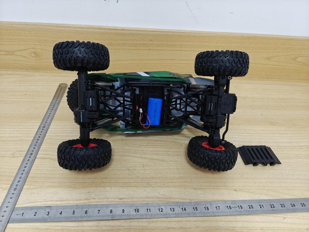
Appendix I External Photographs Page 2 of 3 UL Verification Services (Guangzhou) Co., Ltd, Song Shan Lake Branch This report shall not be reproduced except in full, without the written approval of UL Verification Services (Guangzhou) Co., Ltd, Song Shan Lake Branch. View of EUT-1 View of EUT-2 View of EUT-3 Page 3 of 3 UL Verification Services (Guangzhou) Co., Ltd, Song Shan Lake Branch This report shall not be reproduced except in full, without the written approval of UL Verification Services (Guangzhou) Co., Ltd, Song Shan Lake Branch. View of EUT-4
ID Label/Location Info
27.4MM 56MM 2.1MM 6.4MM FCC ID: 2ASK3GV-6128T FCC ID: 2ASK3SC-2065T This device complies with part 15 of the FCC Rules. Operation is subject to the following two conditions: (1) This device may not cause harmful interference, and (2) this device must accept any interference received, including interference that may cause undesired operation.
Internal Photos
Appendix II Internal Photographs Page 2 of 3 UL Verification Services (Guangzhou) Co., Ltd, Song Shan Lake Branch This report shall not be reproduced except in full, without the written approval of UL Verification Services (Guangzhou) Co., Ltd, Song Shan Lake Branch. Internal View of EUT-1 Internal View of EUT-2 Page 3 of 3 UL Verification Services (Guangzhou) Co., Ltd, Song Shan Lake Branch This report shall not be reproduced except in full, without the written approval of UL Verification Services (Guangzhou) Co., Ltd, Song Shan Lake Branch. Internal View of EUT-3 Antenna
Test Report
The results reported herein have been performed in accordance with the laboratory’s terms of accreditation. This report shall not be reproduced except in full without the written approval of the Laboratory. The results in this report apply to the test sample(s) mentioned above at the time of the testing period only and are not to be used to indicate applicability to other similar products. This report does not imply that the product(s) has met the criteria for certification. CFR 47 FCC PART 15 SUBPART C TEST REPORT For Savage/Savage II MODEL NUMBER: GV-6218/SC-2065/SC-2066/SC-2067/GV-4345/SC-6206/SC- 6207/SC-6208/SC-6153/SC-6154 FCC ID: 2ASK3GV-6128T REPORT NUMBER: 4789459112-2 ISSUE DATE: May 14, 2020 Prepared for AMAX INDUSTRIAL GROUP CHINA CO.,LTD OFFICE NO.3 10/F WITTY COMMERCIAL BUILDING 1A-1L TUNG CHOI STREET MONGKOK KOWLOON HONG KONG Prepared by UL Verification Services (Guangzhou) Co., Ltd, Song Shan Lake Branch Building 10, Innovation Technology Park, No. 1, Li Bin Road, Song Shan Lake Hi- Tech Development Zone Dongguan, 523808, People’s Republic of China Tel: +86 769 22038881 Fax: +86 769 33244054 Website: www.ul.com REPORT NO.: 4789459112-2 Page 2 of 49 UL Verification Services (Guangzhou) Co., Ltd, Song Shan Lake Branch FORM NO.: 10-SL-F0058 This report shall not be reproduced except in full, without the written approval of UL Verification Services (Guangzhou) Co., Ltd, Song Shan Lake Branch. Revision History Rev. Issue Date Revisions Revised By V0 05/14/2020 Initial Issue REPORT NO.: 4789459112-2 Page 3 of 49 UL Verification Services (Guangzhou) Co., Ltd, Song Shan Lake Branch FORM NO.: 10-SL-F0058 This report shall not be reproduced except in full, without the written approval of UL Verification Services (Guangzhou) Co., Ltd, Song Shan Lake Branch. Summary of Test Results Clause Test Items FCC Rules Test Results 1 20dB Bandwidth and 99% Occupied Bandwidth CFR 47 FCC §15.215 (c) Pass 2 Radiated Emission CFR 47 FCC §15.249 (a)(d)(e) CFR 47 FCC §15.205 and §15.209 Pass 3 Antenna Requirement CFR 47 FCC §15.203 Pass Note 1: This test report is only published to and used by the applicant, and it is not for evidence purpose in China. Note 2: The measurement result for the sample received is <Pass> according to < CFR 47 FCC PART 15 SUBPART C > when <Accuracy Method> decision rule is applied. REPORT NO.: 4789459112-2 Page 4 of 49 UL Verification Services (Guangzhou) Co., Ltd, Song Shan Lake Branch FORM NO.: 10-SL-F0058 This report shall not be reproduced except in full, without the written approval of UL Verification Services (Guangzhou) Co., Ltd, Song Shan Lake Branch. TABLE OF CONTENTS 1. ATTESTATION OF TEST RESULTS ................................................................................. 5 2. TEST METHODOLOGY ..................................................................................................... 6 3. FACILITIES AND ACCREDITATION ................................................................................. 6 4. CALIBRATION AND UNCERTAINTY ................................................................................ 7 4.1. MEASURING INSTRUMENT CALIBRATION .............................................................. 7 4.2. MEASUREMENT UNCERTAINTY ............................................................................... 7 5. EQUIPMENT UNDER TEST ............................................................................................... 8 5.1. DESCRIPTION OF EUT .............................................................................................. 8 5.2. MAXIMUM FIELD STRENGTH .................................................................................... 8 5.3. CHANNEL LIST ........................................................................................................... 8 5.4. DESCRIPTION OF AVAILABLE ANTENNAS .............................................................. 9 5.5. TEST CHANNEL CONFIGURATION ........................................................................... 9 5.6. THE WORSE CASE POWER SETTING PARAMETER ............................................... 9 5.7. TEST ENVIRONMENT ................................................................................................ 9 5.8. DESCRIPTION OF TEST SETUP ...............................................................................10 5.9. MEASURING INSTRUMENT AND SOFTWARE USED ..............................................11 6. ANTENNA PORT TEST RESULTS ...................................................................................12 6.1. ON TIME AND DUTY CYCLE .....................................................................................12 6.2. 20 dB BANDWIDTH AND 99% OCCUPIED BANDWIDTH .........................................14 7. RADIATED TEST RESULTS .............................................................................................18 7.1. LIMITS AND PROCEDURE ........................................................................................18 7.2. RESTRICTED BANDEDGE AND FIELD STRENGTH OF INTENTIONAL EMISSIONS 24 7.3. SPURIOUS EMISSIONS (1~3GHz) ............................................................................30 7.4. SPURIOUS EMISSIONS (3~18GHz) ..........................................................................36 7.5. SPURIOUS EMISSIONS (18~26GHz) ........................................................................42 7.6. SPURIOUS EMISSIONS BELOW 30MHz ..................................................................44 7.7. SPURIOUS EMISSIONS BELOW 1GHz AND ABOVE 30MHz ...................................47 8. ANTENNA REQUIREMENTS ............................................................................................49 REPORT NO.: 4789459112-2 Page 5 of 49 UL Verification Services (Guangzhou) Co., Ltd, Song Shan Lake Branch FORM NO.: 10-SL-F0058 This report shall not be reproduced except in full, without the written approval of UL Verification Services (Guangzhou) Co., Ltd, Song Shan Lake Br…
Text truncated - open the document above for the full version.
Test Setup Photos
Appendix II Setup Photographs RADIATED RF MEASUREMENT SETUP (30MHz ~ 1 GHz) RADIATED RF MEASUREMENT SETUP (Below 30MHz) RADIATED RF MEASUREMENT SETUP (Above 1G – X axis) RADIATED RF MEASUREMENT SETUP (Above 1G – Y axis) RADIATED RF MEASUREMENT SETUP (Above 1G – Z axis)
Contact Information
Applicant
Nancy Chen
Test Firm
UL Verification Services (Guangzhou) Co., Ltd.Stephen Guo
[email protected]+86 0769 33817120
Technical Specifications
| # | Rule Parts | Frequency Range | Power Output |
|---|---|---|---|
| 1 | 15C | 2.40 GHz - 2.48 GHz | - |
Other Applications from AMAX INDUSTRIAL GROUP CHINA CO., LTD
2ASK3GV-6587R
May 07, 20241/10 DUNE RUNNER RC AWD OFF ROAD BUGGY
Equipment Class
DXX - Part 15 Low Power Communication Device Transmitter
2ASK3NV-6474R
May 13, 2023Starriders Autonomous RC Drone
Equipment Class
DXX - Part 15 Low Power Communication Device Transmitter
2ASK3GV-6488R
Mar 26, 2023Power Craze Drifter 1/28
Equipment Class
DXX - Part 15 Low Power Communication Device Transmitter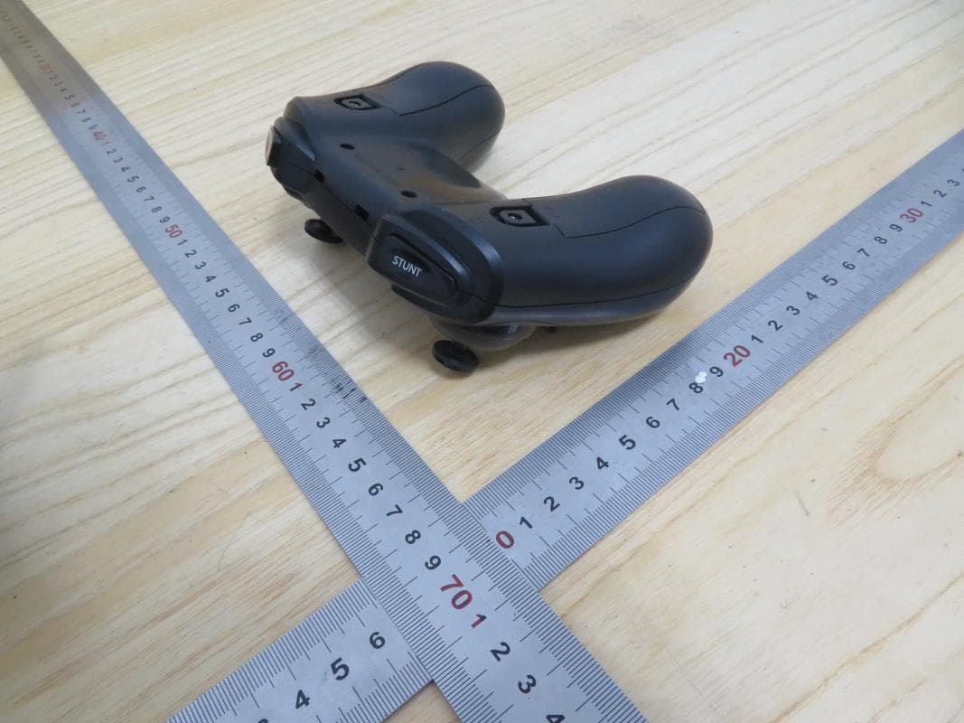
2ASK3CT-6342T
Jul 27, 2021ASC-2400 HD Video drone
Equipment Class
DXX - Part 15 Low Power Communication Device Transmitter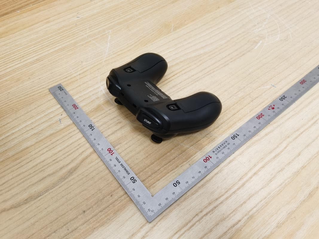
2ASK3SC-6141T
Jul 24, 2021FLEX3.0
Equipment Class
DXX - Part 15 Low Power Communication Device Transmitter