2ASLT-OW30TWS bluetooth headset
SHENZHEN XIWXI TECHNOLOGY CO., LTD
Click to zoom
Application Details
- Equipment Class
- DSS - Part 15 Spread Spectrum Transmitter
- Date of Grant
- Feb 04, 2021
- Application Purpose
- Original Equipment
- Date of Application
- Feb 04, 2021
- Equipment Note
- TWS bluetooth headset
- Frequency Range
- 2402.00000000 - 2480.00000000
- Country
- China
Documents & Files
Document Text
Text extracted from the exhibit documents filed with the FCC. Open a document above to read the original.
Users Manual
PAU PAU PAU LeftRight Product overview L M S √ × OW30 OW30 L M S JP EN CH 商品図面 左耳 右耳 取扱説明書 信号伝送距離のご注意(下の図参照) ≤10m接続安定 10m接続不安定 本製品はリチウム電池を内蔵して います 。爆発を防ぐため、日当たり や火のもとなどから離れて置いてく ださい。 バッテリーについて! 商品規格 欢迎使用本公司的无线电子产品,为了 让您拥有更好的使用体验,请在使用本产品 前仔细阅读操作指南,为避免不必要的伤害 事故发生,请不要自行拆卸本品,请使用标 准充电器。 使用说明书 按键控制 开机取出自动开机 关机放回充电仓自动关机 音量-左耳长按触摸MFB键 下一曲右耳触摸3次MFB键 上一曲左耳触摸3次MFB键 音量+右耳长按触摸MFB键 播放/暂停左/右耳触摸MFB键2次 接听电话左/右耳触摸MFB键2次 参数规格 版本V5.0 支持A2DP,AVRCP,HFP,HSP 传输距离≥10m 频率范围2.402GHz~2.480GHz 喇叭Φ10mm*2 阻抗32Ω 待机时间70小时 通话时间4小时 音乐播放时间4小时 耳机电池容量40mAh 耳机充电时长1小时 充电仓电池容量420mAh 充电仓充电时长约1小时 重量(单个耳机)4.0 g 信号传输距离注意(如下图) ≤10m信号正常 10m信号会间断 注意事项 此产品内置锂电池,请勿将产品暴露 在强烈的日晒下、火烤或扔入火中, 以免爆炸。 电池警告 ! 中 英 文 英 日 文 材质:128g铜版纸 尺寸:70*50mm 装订:风琴折,正反面 只做英日文 防水 日常生活防水只要是非浸泡的都可以,可以带 着洗澡、洗脸、淋雨、但不能潜水和泡澡...... 1.不要潜水时使用本品,因为水会封锁住信号. 2.不要使用具有腐蚀性的溶剂来清洗该设备。 3.不小心接触到化学物品,请用清水彻底的清 洗。 4.不要将设备置于低于-10°C或高于60°C的极端 环境温度下使用。 5.不要将设备投掷于火中,避免产生爆炸。 6.不要用尖锐物品触碰耳机,否则易造成刮伤 。 7.不要将任何杂物插进耳机中,否则易损伤电 子元件。 8.不要尝试拆解耳机。 9.不要长时间静置本产品,如有超过一个月未 使用,请及时充电保养以确保正常工作。 10.不要使用电流量大于2A的电源适配器给本产 品充电,电流量过大会对电池产生损坏。 Power on Automatically turn on when take-out case Power offAutomatically turn off when back into case Previous track Triple tap left earbud MFB Button Next track Triple tap right earbud MFB Button Volume - Hold and press left earbud MFB Button Volume + Hold and press right earbud MFB Button Play / Pause double tap any MFB Button Answer the calldouble tap any MFB Button Hang updouble tap any MFB Button Reject callhold and press any MFB Button for about 2s Voice activated assistant tap any MFB Button 4 times 日常 生活での非浸水使用 は大丈 夫です 。着用 したまま、シャワー、洗顔、雨などは大丈夫です が、水 泳、潜 水時は 対応できません。 水泳 、潜水雨、シャワー 防水 注意事項 1. 信号は水中に転送できないため、潜水時に本品は使 えません。 2. 腐食性の溶剤で洗わないでください。 3. 化学物質と接触した場合は、水で十分に洗浄してくだ さい。 4. 本商品は-10~60°Cの環境でご使用ください。 5. 爆発を防ぐため、本品を火から離れて置いてください。 6. 傷、破損を防ぐために本製品を鋭利なものへ引っか からないようにご注意くださ い。 7. イヤホンの電子部品の損傷を防ぐため、小物をイヤホ ンの中に入れないでください。 8. お客様自らのご修理、ご解体などは絶対にやめてくだ さい。 9. 長時間使用する予定がない場合(1ヶ月以上)、本製 品の性能を保護するために時折充電をしてください。 10. 2A以上の過大な電流はバッテリーに損害を与える恐 れがあります。2A以上の充電アダプターのご使用は絶 対にやめてください。 インジケータ There is a built-in lithium battery in this product. To avoid explosion, do NOT expose the product to strong sunlight, fire or throw it into fire. Battery Warning Attentions 1.Please do not use this product while diving as water will block signal. 2.Do not use corrosive liquid to clean this product. 3..If this product is accidentally exposed to chemicals, clean it with water 4.Do not use this product under extreme circumstances for temperature below -10 degree Celsius or above 60 degree Celsius . 5.To avoid explosion, please do not throw this product into fire. 6.To avoid scratches, please do not touch the earbuds with sharp objects. 7.Do not insert objects into the earbuds, otherwise it would cause damage to the internal components. 8.Do not disassemble the earbud. 9. Please keep regular charge to earbuds, don’t leave them become empty battery status to keep their lifetime. 10. Please do not charge products with power adapter over 2A current. Excessive current may cause the damage to battery. Signal transmission distance shown as below: ≤10m Signals is in normal transmission. 10m Signals will be interrupted. Waterproof √ × Ear caps S、M、L三種類のイヤーピースを付属しており。 ご自身の場合によって、フィット感がいいイヤー ピースをご使用ください。 耳机操作 设置 蓝牙 P3 蓝牙 现在可被发现为”Qi的iPhone”。 我的设备 请前往Watch应用配对Apple Watch和iPhone。 单机模式 双机模式 充电 恢复出厂设置 挂断电话左/右耳触摸MFB键2次 拒接来电 左/右耳长按触摸MFB键约2s 语音助手激活 轻触左/右耳机MFB键4下 Settings Bluetooth P3 Bluetooth Now discoverable as”Qi iPhone ”. MYDEVICES To pair Apple Watch with your iPhone, go to the Watch app. Charge Settings Bluetooth P3 Bluetooth Now discoverable as”Qi iPhone”. MYDEVICES To pair Apple Watch with your iPhone, go to the Watch app. イヤホンの使い方 耳机充电 1.将左右耳机放入充电盒内,耳机亮红灯进入 充电状态。 2.耳机充电过程长亮红灯。 3.耳机充满电后红灯熄灭,蓝灯亮几秒后熄灭。 充电仓充电 请使用输出电压为DC5V/1A的充电器 对充电仓充电,可使用电脑USB或其他USB接口的 充电器充电(必须选择正规厂家认证过的充电器)。 充电警告 充电状态时,请勿按压耳机电源键, 否则会造成无法配对,此时需要恢复出厂设置。 首次配对使用双耳机说明 提示:当首次使用时左右耳机不能配对,出现 任一边无声,可按如下操作: 1.从充电仓内取出耳机并移除绝缘膜, 2.将两个耳机放回充电仓充电(红灯亮后激活耳机)。 3.再取出两个耳机,耳机会自动开机互联并进入等待 配对模式, 4.打开手机蓝牙功能并搜索,找到“P3”名称并点击 连接即可 1.清空记录:先将手机蓝牙关闭,并且耳机已 关机,在关机状态下触摸MFB键约5秒后松手, 耳机会进入配对状态(红/蓝灯交替闪烁), 然后快速5次触摸MFB键,红灯亮1秒后恢复 出厂设置并自动关机。 2.耳机恢复出厂设置后,需将手机历史连接记 录“P3”删除,再重新搜索连接。 √ × 产品示意图 左耳 右耳 磁吸触点 充电仓指示灯 Type-C充电口 耳机指示灯 MFB电源触摸按键 MIC 耳机帽 耳帽选择 我们提供了大中小三种规格耳帽,请尝试先择适 合自己的尺寸以便获得更佳的使用体验。 1.两个耳机在关机状态下,同时按住两个耳机 MFB键8秒后蓝灯快闪松开进入左右耳机自动配 对模式,配对成功后会进入等待与手机配对模 式(红/蓝灯交替闪烁),打开手机蓝牙功能并 搜索“P3”点击连接即可。 左、右耳机互联配对 充电仓指示灯 耳机指示灯 LED指示灯 状态 灯光 开机 蓝灯闪1秒 关机 红灯闪1秒 搜索耳机 红蓝交替闪烁 耳机连接成功 蓝灯6秒循环闪烁 音乐状态 无亮灯 电池电量低 红灯闪烁 充电中 红灯长亮 充满 红灯熄灭转蓝灯亮5秒熄灭 本社のワイヤレス製品を購入いただき、誠 にありがとうございます。より良い使用感を得る ため、ご使用前にマニュアルをお読みください。 事故を避けるため、本製品の解体はご遠慮くだ さい。付属充電器で充電することをお願いします。 MFBタッチボタン ケースインジケータ Type-C充電口 マイク イヤピースー 磁気充電接点 イヤーピースの付け方 耳に一番フィットのイヤーピースを使用してください。 1.両耳イヤホンを取り出して充電接点に貼り付けている絶縁 膜を剥がしてください。 2.両耳イヤホンをケースに戻してください。(イヤホンは充電 状態になり、赤ランプが点灯します。) 3.再度同時に両耳イヤホンを取り出しますとイヤホンが自動 起動する上に左右ペアリングモードに入ります。 4.スマホのブルートゥース機能をオンにし、デバイス一覧から 【P3】というデバイスを選択して接続させてください。 両耳ペアリング操作説明 まずスマホ等端末のブルートゥース機能とイヤホン電源 をオフにしてからイヤホンボタンを8秒ほどロングタッチす ると、両耳イヤホン青ランプが点滅し左右ペアリングモー ドに入ります。左右ペアリング完了後に赤青ランプが交互 に点滅します。イヤホンブルート ゥース機能を起動して 「P3」を選択すれば接続できます。 ご注意:初回の使用に両耳接続不能やどちらかの一方は音声 が流れない場合、以下の手順で操作してください。 左右イヤホンの接続方法 LED 充電ケースインジケータ 状態点灯表示 電源オン青ランプ一秒間点灯 電源オフ赤ランプ一秒間点灯 左右ペアリング中赤青交互に点滅 左右ペアリング完成 青ランプ6秒間点滅 再生中 消灯 低電量赤ランプ点滅 充電中赤ランプ点灯 充電終了 赤ランプから青に変更5秒後に消灯 イヤホンインジケータ 充電について イヤホンを誤って操作し、電話との接続に失敗した場合 は、次のように再ペアリングしてください。 イヤホンの充電: 1.イヤホンをケースに戻すと、充電し始めます。 2.赤ランプが点灯。 3.充電完了後に赤ランプから青に変更し、数秒後に消灯。 初期化方法 MFBボタン機能紹介 バージョンV5.0 プロファイルA2DP,AVRCP,HPF,HSP 通信距離≥10 m 使用周波数2.402GHz~2.480GHz オーディオΦ10mm*2 電気抵抗32Ω 待受時間70時間 通話時間4時間 音楽再生時間4時間 イヤホンバッテリー容量40mAh イヤホン充電時間1時間 充電ケースバッテリー容量420mAh 充電ケースの充電時間約1時間 片耳イヤホンの重量4.0g 充電警告:左右ペアリングできなくならないように、充 電状態中のイヤホンボタンをタッチしないでください。 万が一の場合は、イヤホンを初期化してください。 1.記録消去:スマホのブルートゥース機能とイヤホンの 電源をオフにする状態で同時に両耳イヤホンMFBボタ ンを5秒間ロングタッチすると左右イヤホンがペアリン グモードになり、赤青ランプが交互に点滅します。また 5回連続タッチしますと赤ランプが一秒間点灯してから 初期化完成します。 2.イヤホンを初期化完成後に前にスマホ側登録された ”P3”というデバイスを一旦解除してもう一度検索して 接続させてください。 充電ケースの充電: 必ず出力DC5V/0.5Aの充電器を使用してください。パ ソコン等USBの挿し口がある機器を利用可能です。 (ご注意:認証済みの充電器をご利用ください。) 電源オン ケースから取り出されると電源オン 電源オフケースに戻されると…
Text truncated - open the document above for the full version.
Cover Letter(s)
Rev 11/20/07 (SHENZHEN XIWXI TECHNOLOGY CO., LTD) Federal Communications Commission Authorization and Evaluation Division Confidentiality Request regarding application for certification of FCC ID: 2ASLT-OW30 Pursuant to Sections 0.457 and 0.459 of the Commission’s Rules, we hereby request confidential treatment of information accompanying this application as outlined below: Exhibit Type File Name Block Diagram, Schematics, Operational Description Block Diagram Schematics Operational Description The above materials contain trade secrets and proprietary information not customarily released to the public. The public disclosure of these materials may be harmful to the applicant and provide unjustified benefits to its competitors. The applicant understands that pursuant to Section 0.457 of the Rules, disclosure of this application and all accompanying documentation will not be made before the date of the Grant for this application. Sincerely, ( LI HAIBO)
Cover Letter(s)
(SHENZHEN XIWXI TECHNOLOGY CO., LTD) Federal Communications Commission Authorization and Evaluation Division 1435 Oakland Mills Road Columbia, MD 21046 Date: 2021/02/04 SUBJECT: FCC Application for FCC ID: 2ASLT-OW30 To Whom It May Concern: We, the undersigned, hereby authorize Alan Mei at Shenzhen BCTC Testing Co., Ltd. on our behalf, to apply to the Federal Communications Commission on our equipment. Any and all acts carried out by Alan Mei of Shenzhen BCTC Testing Co., Ltd. on our behalf shall have the same effect as acts of our own. This is to advise that we are in full compliance with the Anti- Drug Abuse Act. We, the applicant, are not subject to a denial of federal benefits pursuant to Section 5301 of the Anti-Drug Act of 1988, 21 USC853a, and no party to the application is subject to a denial of federal benefits pursuant to that section. Regards ( LI HAIBO)
External Photos
External Photos
ID Label/Location Info
Label & label location FCC ID: 2ASLT-OW30 Label location Label location
Internal Photos
Internal Photos Antenna Antenna
RF Exposure Info
RF EXPOSURE EVALUATION METHOD FCC ID: 2ASLT-OW30 SAR Test Exclusion Thresholds for 100 MHz – 6 GHz and ≤ 50 mm Approximate SAR Test Exclusion Power Thresholds at Selected Frequencies and Test Separation Distances are illustrated in the following Table. The 1-g and 10-g SAR test exclusion thresholds for 100 MHz to 6 GHz at test separation distances ≤ 50 mm are determined by: [(max. power of channel, including tune-up tolerance, mW)/(min. test separation distance, mm)] · [√f(GHz)] ≤ 3.0 for 1-g SAR and ≤ 7.5 for 10-g extremity SAR,where f(GHz) is the RF channel transmit frequency in GHz Power and distance are rounded to the nearest mW and mm before calculation The result is rounded to one decimal place for comparison The test exclusions are applicable only when the minimum test separation distance is ≤ 50 mm and for transmission frequencies between 100 MHz and 6 GHz. When the minimum test separation distance is < 5 mm, a distance of 5 mm is applied to determine SAR test exclusion. BT-EDR Left max possible output power (PK,conducted):5±1dbm 1.72dBi logarithmic terms convert to numeric result is nearly 1..486. 6dbm=3.98mW 2402MHz [(max. power of channel, including tune-up tolerance, mW)/(min. test separation distance,mm)] · [√f(GHz)]=3.98/5*√2.402 =1.23≤3.0 Threshold at which no SAR required is 10mw and ≤ 3.0 for 1-g SAR, Separation distance is 5mm. Modulation Frequency (MHz) Output Power (dBm) Max Antenna Gain (dBi) GFSK 2402 0.811 1.72 GFSK 2441 1.264 1.72 GFSK 2480 1.380 1.72 Pi/4 DQPSK 2402 3.261 1.72 Pi/4 DQPSK 2441 3.699 1.72 Pi/4 DQPSK 2480 3.803 1.72 8DPSK 2402 3.840 1.72 8DPSK 2441 4.276 1.72 8DPSK 2480 4.372 1.72 2441MHz [(max. power of channel, including tune-up tolerance, mW)/(min. test separation distance,mm)] · [√f(GHz)]=3..98/5*√2.441 =1.24≤3.0 Threshold at which no SAR required is 10mw and ≤ 3.0 for 1-g SAR, Separation distance is 5mm. 2480MHz [(max. power of channel, including tune-up tolerance, mW)/(min. test separation distance,mm)] · [√f(GHz)]=3.98/5*√2.48=1.25≤3.0 Threshold at which no SAR required is 10mw and ≤ 3.0 for 1-g SAR, Separation distance is 5mm. Conclusion: No SAR is required. Right max possible output power (PK,conducted):4±1dbm 1.72dBi logarithmic terms convert to numeric result is nearly 1..486. 5dbm=3.16mW 2402MHz [(max. power of channel, including tune-up tolerance, mW)/(min. test separation distance,mm)] · [√f(GHz)]=3.16/5*√2.402 =0.98≤3.0 Threshold at which no SAR required is 10mw and ≤ 3.0 for 1-g SAR, Separation distance is 5mm. Modulation Frequency (MHz) Output Power (dBm) Max Antenna Gain (dBi) GFSK 2402 0.361 1.72 GFSK 2441 0.661 1.72 GFSK 2480 0.639 1.72 Pi/4 DQPSK 2402 2.824 1.72 Pi/4 DQPSK 2441 3.139 1.72 Pi/4 DQPSK 2480 3.091 1.72 8DPSK 2402 3.357 1.72 8DPSK 2441 3.705 1.72 8DPSK 2480 3.669 1.72 2441MHz [(max. power of channel, including tune-up tolerance, mW)/(min. test separation distance,mm)] · [√f(GHz)]=3. 16/5*√2.441 =0.99≤3.0 Threshold at which no SAR required is 10mw and ≤ 3.0 for 1-g SAR, Separation distance is 5mm. 2480MHz [(max. power of channel, including tune-up tolerance, mW)/(min. test separation distance,mm)] · [√f(GHz)]=3.16/5*√2.48=1.00≤3.0 Threshold at which no SAR required is 10mw and ≤ 3.0 for 1-g SAR, Separation distance is 5mm. Conclusion: No SAR is required.
Test Report
No.:BCTC/RF-EMC-005 Page 1 of 105 Edition:A.3 TEST REPORT Shenzhen BCTC Testing Co., Ltd. Report No.: BCTC2101628756E Applicant: SHENZHEN XIWXI TECHNOLOGY CO., LTD Product Name: TWS bluetooth headset Model/Type reference: P3 (OW30) Tested Date: 2021-01-21 to 2021-01-29 Issued Date: 2021-01-29 Report No.: BCTC2101628756E No.:BCTC/RF-EMC-005 Page 2 of 105 Edition:A.3 FCC ID: 2ASLT-OW30 The test report is effective only with both signature and specialized stamp.This result(s) shown in this report refer only to the sample(s) tested. Without written approval of Shenzhen BCTC Testing Co., Ltd, this report can’t be reproduced except in full.The tested sample(s) and the sample information are provided by the client. Product Name: TWS bluetooth headset Trademark: N/A Model/Type reference: P3 (OW30) Prepared For: SHENZHEN XIWXI TECHNOLOGY CO., LTD Address: No. 47, the 3rd Shabo Road, Shajing Town, Bao'an District, Shenzhen, China Manufacturer: SHENZHEN XIWXI TECHNOLOGY CO., LTD Address: No. 47, the 3rd Shabo Road, Shajing Town, Bao'an District, Shenzhen, China Prepared By: Shenzhen BCTC Testing Co., Ltd. Address: 1-2/F., Building B, Pengzhou Industrial Park, No.158, Fuyuan 1st Road, Tangwei, Fuhai Subdistrict, Bao'an District, Shenzhen, Guangdong, China Sample Received Date: 2021-01-21 Sample tested Date: 2021-01-21 to 2021-01-29 Issue Date: 2021-01-29 Report No.: BCTC2101628756E Test Standards FCC Part15.247 ANSI C63.10-2013 Test Results PASS Remark: This is Bluetooth Classic radio test report. Tested by: Approved by: Willem Wang/Project Handler Zero Zhou/Reviewer Report No.: BCTC2101628756E No.:BCTC/RF-EMC-005 Page 3 of 105 Edition:A.3 TABLE OF CONTENT Test Report Declaration Page 1. VERSION ............................................................. 5 2. TEST SUMMARY ...................................................... 6 3. MEASUREMENT UNCERTAINTY ........................................ 7 4. PRODUCT INFORMATION AND TEST SETUP ............................ 8 4.1 Product Information ..................................................... 8 4.2 Test Setup Configuration ................................................ 8 4.3 Support Equipment ..................................................... 9 4.4 Channel List ........................................................... 9 4.5 Test Mode ............................................................ 10 4.6 table of parameters of text software setting ................................ 10 5. TEST FACILITY AND TEST INSTRUMENT USED ........................ 11 5.1 Test Facility ........................................................... 11 5.2 Test Instrument Used .................................................. 11 6. CONDUCTED EMISSIONS ............................................. 13 6.1 Block Diagram Of Test Setup ............................................ 13 6.2 Limit ................................................................. 13 6.3 Test procedure ........................................................ 13 6.4 EUT operating Conditions ............................................... 14 6.5 Test Result ........................................................... 15 7. RADIATED EMISSIONS ............................................... 17 7.1 Block Diagram Of Test Setup ............................................ 17 7.2 Limit ................................................................. 18 7.3 Test procedure ........................................................ 19 7.4 EUT operating Conditions ............................................... 21 7.5 Test Result ........................................................... 22 8. RADIATED BAND EMISSION MEASUREMENT AND RESTRICTED BANDS OF OPERATION ................................................... 27 8.1 Block Diagram Of Test Setup ............................................ 27 8.2 Limit ................................................................. 27 8.3 Test procedure ........................................................ 28 8.4 EUT operating Conditions ............................................... 28 8.5 Test Result ........................................................... 29 9. CONDUCTED EMISSION .............................................. 31 9.1 Block Diagram Of Test Setup ............................................ 31 9.2 Limit ................................................................. 31 9.3 Test procedure ........................................................ 31 9.4 Test Result ........................................................... 31 10. 20 DB BANDWIDTH .................................................. 50 10.1 Block Diagram Of Test Setup .......................................... 50 Report No.: BCTC2101628756E No.:BCTC/RF-EMC-005 Page 4 of 105 Edition:A.3 10.2 Limit ................................................................ 50 10.3 Test procedure ....................................................... 50 10.4 Test Result .......................................................... 51 11. MAXIMUM PEAK OUTPUT POWER .................................... 61 11.1 Block Diagram Of Test Setup .......................................... 61 11.2 Limit ................................................................ 61 11.3 Test procedure ....................................................... 61 11.4 Test Result .......................................................... 62 12. HOPPING CHANNEL SEPARATION .................................... 72 12.1 Block Diagram Of Test Setup .......................................... 72 12.2 Limit ................................................................ 72 12.3 Test procedure ....................................................... 72 12.4 Test Result .......................................................... 73 13. NUMBER OF HOPPING FREQUENCY .................................. 83 13.1 Block Diagram Of Test Setup .......................................... 83 13.2 Limit ....................................................…
Text truncated - open the document above for the full version.
Test Report
Report No.: BCTC2101628756E No.:BCTC/RF-EMC-005 Page 44 of 105 Edition:A.3 GFSK Transmitting Band edge-left side GFSK Hopping Band edge-left side Report No.: BCTC2101628756E No.:BCTC/RF-EMC-005 Page 45 of 105 Edition:A.3 GFSK Transmitting Band edge-right side GFSK Hopping Band edge-right side Report No.: BCTC2101628756E No.:BCTC/RF-EMC-005 Page 46 of 105 Edition:A.3 Pi/4 DQPSK Transmitting Band edge-left side Pi/4 DQPSK Hopping Band edge-left side Report No.: BCTC2101628756E No.:BCTC/RF-EMC-005 Page 47 of 105 Edition:A.3 Pi/4 DQPSK Transmitting Band edge-right side Pi/4 DQPSK Hopping Band edge-right side Report No.: BCTC2101628756E No.:BCTC/RF-EMC-005 Page 48 of 105 Edition:A.3 8DPSK Transmitting Band edge-left side 8DPSK Hopping Band edge-left side Report No.: BCTC2101628756E No.:BCTC/RF-EMC-005 Page 49 of 105 Edition:A.3 8DPSK Transmitting Band edge-right side 8DPSK Hopping Band edge-right side Report No.: BCTC2101628756E No.:BCTC/RF-EMC-005 Page 50 of 105 Edition:A.3 10. 20 DB BANDWIDTH 10.1 Block Diagram Of Test Setup 10.2 Limit N/A 10.3 Test procedure 1. Set RBW = 30kHz. 2. Set the video bandwidth (VBW) ≥ 3 x RBW. 3. Detector = Peak. 4. Trace mode = max hold. 5. Sweep = auto couple. 6. Allow the trace to stabilize. 7. Measure the maximum width of the emission that is constrained by the frequencies associated with the two outermost amplitude points (upper and lower frequencies) that are attenuated by 6 dB relative to the maximum level measured in the fundamental emission. . Report No.: BCTC2101628756E No.:BCTC/RF-EMC-005 Page 51 of 105 Edition:A.3 10.4 Test Result Temperature: 26°C Relative Humidity: 54% Test Voltage : DC 3.7V Remark N/A Left Modulation Test Channel Bandwidth(MHz) GFSK Low 0.952 GFSK Middle 0.949 GFSK High 0.953 Pi/4 DQPSK Low 1.289 Pi/4 DQPSK Middle 1.286 Pi/4 DQPSK High 1.286 8DPSK Low 1.294 8DPSK Middle 1.285 8DPSK High 1.300 Test plots GFSK Low Channel Report No.: BCTC2101628756E No.:BCTC/RF-EMC-005 Page 52 of 105 Edition:A.3 GFSK Middle Channel GFSK High Channel Report No.: BCTC2101628756E No.:BCTC/RF-EMC-005 Page 53 of 105 Edition:A.3 Pi/4 DQPSK Low Channel Pi/4 DQPSK Middle Channel Report No.: BCTC2101628756E No.:BCTC/RF-EMC-005 Page 54 of 105 Edition:A.3 Pi/4 DQPSK High Channel 8DPSK Low Channel Report No.: BCTC2101628756E No.:BCTC/RF-EMC-005 Page 55 of 105 Edition:A.3 8DPSK Middle Channel 8DPSK High Channel Report No.: BCTC2101628756E No.:BCTC/RF-EMC-005 Page 56 of 105 Edition:A.3 Right Modulation Test Channel Bandwidth(MHz) GFSK Low 0.949 GFSK Middle 0.955 GFSK High 0.952 Pi/4 DQPSK Low 1.285 Pi/4 DQPSK Middle 1.290 Pi/4 DQPSK High 1.271 8DPSK Low 1.295 8DPSK Middle 1.297 8DPSK High 1.298 Test plots GFSK Low Channel Report No.: BCTC2101628756E No.:BCTC/RF-EMC-005 Page 57 of 105 Edition:A.3 GFSK Middle Channel GFSK High Channel Report No.: BCTC2101628756E No.:BCTC/RF-EMC-005 Page 58 of 105 Edition:A.3 Pi/4 DQPSK Low Channel Pi/4 DQPSK Middle Channel Report No.: BCTC2101628756E No.:BCTC/RF-EMC-005 Page 59 of 105 Edition:A.3 Pi/4 DQPSK High Channel 8DPSK Low Channel Report No.: BCTC2101628756E No.:BCTC/RF-EMC-005 Page 60 of 105 Edition:A.3 8DPSK Middle Channel 8DPSK High Channel Report No.: BCTC2101628756E No.:BCTC/RF-EMC-005 Page 61 of 105 Edition:A.3 11. MAXIMUM PEAK OUTPUT POWER 11.1 Block Diagram Of Test Setup 11.2 Limit FCC Part15 (15.247) , Subpart C Section Test Item Limit Frequency Range (MHz) Result 15.247(b)(1) Peak Output Power 0.125 watt or 21dBm 2400-2483.5 PASS 11.3 Test procedure 1. Remove the antenna from the EUT and then connect a low RF cable from the antenna port to the spectrum. 2. Set the spectrum analyzer: RBW = 3MHz. VBW = 3MHz. Sweep = auto; Detector Function = Peak. 3. Keep the EUT in transmitting at lowest, medium and highest channel individually. Record the max value. Report No.: BCTC2101628756E No.:BCTC/RF-EMC-005 Page 62 of 105 Edition:A.3 11.4 Test Result Temperature: 26°C Relative Humidity: 54% Test Voltage : DC 3.7V Remark: N/A Left Modulation Test Channel Output Power (dBm) Limit (dBm) GFSK Low 0.811 21 GFSK Middle 1.264 21 GFSK High 1.380 21 Pi/4 DQPSK Low 3.261 21 Pi/4 DQPSK Middle 3.699 21 Pi/4 DQPSK High 3.803 21 8DPSK Low 3.840 21 8DPSK Middle 4.276 21 8DPSK High 4.372 21 Test plots GFSK Low Channel Report No.: BCTC2101628756E No.:BCTC/RF-EMC-005 Page 63 of 105 Edition:A.3 GFSK Middle Channel GFSK High Channel Report No.: BCTC2101628756E No.:BCTC/RF-EMC-005 Page 64 of 105 Edition:A.3 Pi/4 DQPSK Low Channel Pi/4 DQPSK Middle Channel Report No.: BCTC2101628756E No.:BCTC/RF-EMC-005 Page 65 of 105 Edition:A.3 Pi/4 DQPSK High Channel 8DPSK Low Channel Report No.: BCTC2101628756E No.:BCTC/RF-EMC-005 Page 66 of 105 Edition:A.3 8DPSK Middle Channel 8DPSK High Channel Report No.: BCTC2101628756E No.:BCTC/RF-EMC-005 Page 67 of 105 Edition:A.3 Right Modulation Test Channel Output Power (dBm) Limit (dBm) GFSK Low 0.361 21 GFSK Middle 0.661 21 GFSK High 0.639 21 Pi/4 DQPSK Low 2.824 21 Pi/4 DQPSK Middle 3.139 21 Pi/4 DQPSK High 3.091 21 8DPSK Low 3.357 21 8DPSK Middle 3.705 21 8DPSK High 3.669 21 Test plots GFSK Low Channel Report No.: BCTC2101628756E No.:BCTC/RF-EMC-005 Page 68 of 105 Edition:A.3 GFSK Middle Channel GFSK High Channel Report No.: BCTC2101628756E No.:BCTC/RF-EMC-005 Page 69 of 105 Edition:A.3 Pi/4 DQPSK Low Channel Pi/4 DQPSK Middle Channel Report No.: BCTC2101628756E No.:BCTC/RF-EMC-005 Page 70 of 105 Edition:A.3 Pi/4 DQPSK High Channel 8DPSK Low Channel Report No.: BCTC2101628756E No.:BCTC/RF-EMC-005 Page 71 of 105 Edition:A.3 8DPSK Middle Channel 8DPSK High Channel Report No.: BCTC2101628756E No.:BCTC/RF-EMC-005 Page 72 of 105 Edition:A.3 12. HOPPING CHANNEL SEPARATION 12.1 Block Diagram Of Test Setup 12.2 Limit Frequency hopping systems shall have hopping channel carrier frequencies separated by a minimum of 25 kHz or the 20 dB bandwidth of the hopping channel, whichever is greater. Alternatively, frequency hopping systems operating in the 2400-2483.5 MHz band may have hopping channel carrier frequencies that are se…
Text truncated - open the document above for the full version.
Test Report
Report No.: BCTC2101628756E No.:BCTC/RF-EMC-005 Page 95 of 105 Edition:A.3 Right Modulation Channel Data Packet pulse time(ms) Dwell Time(s) Limits(s) GFSK Middle DH1 0.386 0.124 0.4 DH3 1.656 0.265 0.4 DH5 2.910 0.310 0.4 Pi/4DQPSK Middle 2DH1 0.394 0.126 0.4 2DH3 1.656 0.265 0.4 2DH5 2.910 0.310 0.4 8DPSK Middle 3DH1 0.394 0.126 0.4 3DH3 1.656 0.265 0.4 3DH5 2.910 0.310 0.4 Test Plots GFSK DH1 Middle Channel Report No.: BCTC2101628756E No.:BCTC/RF-EMC-005 Page 96 of 105 Edition:A.3 GFSK DH3 Middle Channel GFSK DH5 High Middle Channel Report No.: BCTC2101628756E No.:BCTC/RF-EMC-005 Page 97 of 105 Edition:A.3 Pi/4DQPSK DH1 Middle Channel Pi/4DQPSK DH3 Middle Channel Report No.: BCTC2101628756E No.:BCTC/RF-EMC-005 Page 98 of 105 Edition:A.3 Pi/4DQPSK DH5 Middle Channel 8DPSK DH1 Middle Channel Report No.: BCTC2101628756E No.:BCTC/RF-EMC-005 Page 99 of 105 Edition:A.3 8DPSK DH3 Middle Channel 8DPSK DH5 Middle Channel Report No.: BCTC2101628756E No.:BCTC/RF-EMC-005 Page 100 of 105 Edition:A.3 15. ANTENNA REQUIREMENT 15.1 Limit 15.203 requirement: For intentional device, according to 15.203: an intentional radiator shall be designed to ensure that no antenna other than that furnished by the responsible party shall be used with the device. 15.2 Test Result The EUT antenna is Chip antenna, The antenna is 1.72dBi, fulfill the requirement of this section. Report No.: BCTC2101628756E No.:BCTC/RF-EMC-005 Page 101 of 105 Edition:A.3 16. EUT PHOTOGRAPHS EUT Photo 1 EUT Photo 2 Report No.: BCTC2101628756E No.:BCTC/RF-EMC-005 Page 102 of 105 Edition:A.3 17. EUT TEST SETUP PHOTOGRAPHS Conducted emissions Radiated Measurement Photos Report No.: BCTC2101628756E No.:BCTC/RF-EMC-005 Page 103 of 105 Edition:A.3 Left Report No.: BCTC2101628756E No.:BCTC/RF-EMC-005 Page 104 of 105 Edition:A.3 Right Report No.: BCTC2101628756E No.:BCTC/RF-EMC-005 Page 105 of 105 Edition:A.3 STATEMENT 1.The equipment lists are traceable to the national reference standards. 2.The test report can not be partially copied unless prior written approval is issued from our lab. 3.The test report is invalid without stamp of laboratory. 4.The test report is invalid without signature of person(s) testing and authorizing. 5.The test process and test result is only related to the Unit Under Test. 6.The quality system of our laboratory is in accordance with ISO/IEC17025. 7.If there is any objection to report, the client should inform issuing laboratory within 15 days from the date of receiving test report. Address: 1-2/F., Building B, Pengzhou Industrial Park, No.158, Fuyuan 1st Road, Tangwei, Fuhai Subdistrict, Bao'an District, Shenzhen, Guangdong, China TEL:400-788-9558 P. C.: 518103 FAX:0755-33229357 Website:http://www.bctc-lab.com E-Mail:[email protected] ※※※※※ END ※※※※※
Test Setup Photos
Report No.: BCTC2101628756E No.:BCTC/RF-EMC-005 Page 102 of 105 Edition:A.3 17. EUT TEST SETUP PHOTOGRAPHS Conducted emissions Radiated Measurement Photos Report No.: BCTC2101628756E No.:BCTC/RF-EMC-005 Page 103 of 105 Edition:A.3 Left Report No.: BCTC2101628756E No.:BCTC/RF-EMC-005 Page 104 of 105 Edition:A.3 Right
Contact Information
Applicant
LI HAIBO(Manager)
Test Firm
Shenzhen BCTC Testing Co., Ltd.Sally He
[email protected]15999690624
Technical Specifications
| # | Rule Parts | Frequency Range | Power Output |
|---|---|---|---|
| 1 | 15C | 2.40 GHz - 2.48 GHz | 2.74 mW |
Other Applications from SHENZHEN XIWXI TECHNOLOGY CO., LTD
2ASLT-DBK03
Jul 12, 2021TWS Bluetooth headset
Equipment Class
DSS - Part 15 Spread Spectrum Transmitter
2ASLT-V8
May 16, 2021TWS Bluetooth headset
Equipment Class
DSS - Part 15 Spread Spectrum Transmitter
2ASLT-V6L
May 09, 2021TWS Bluetooth headset
Equipment Class
DSS - Part 15 Spread Spectrum Transmitter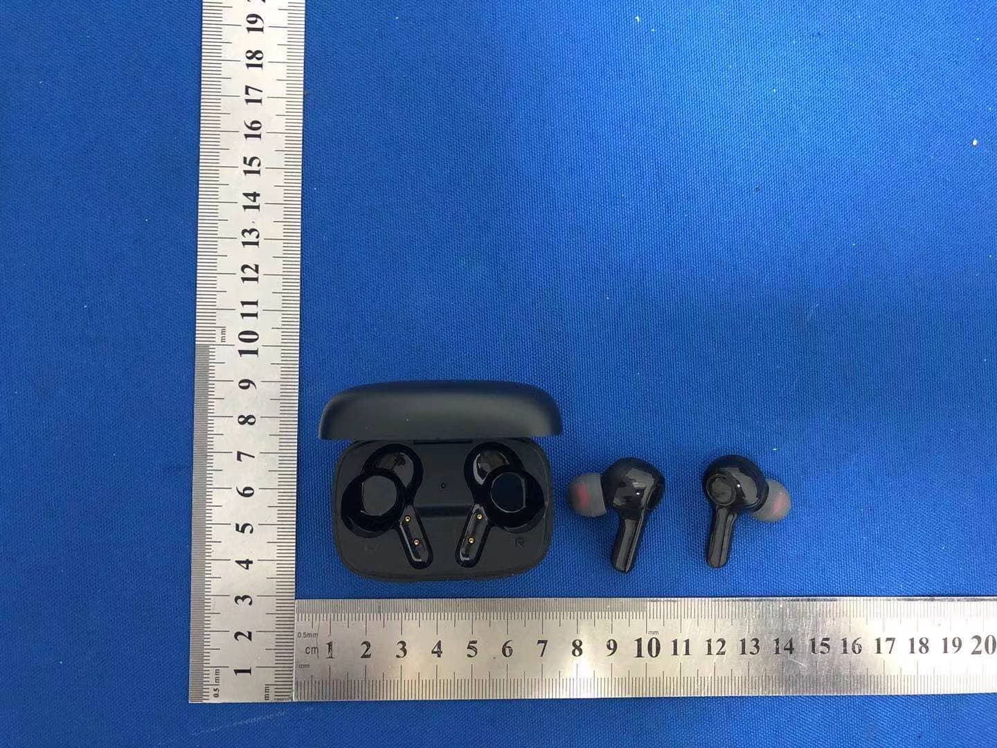
2ASLT-DBK01
Apr 29, 2021TWS Bluetooth headset
Equipment Class
DSS - Part 15 Spread Spectrum Transmitter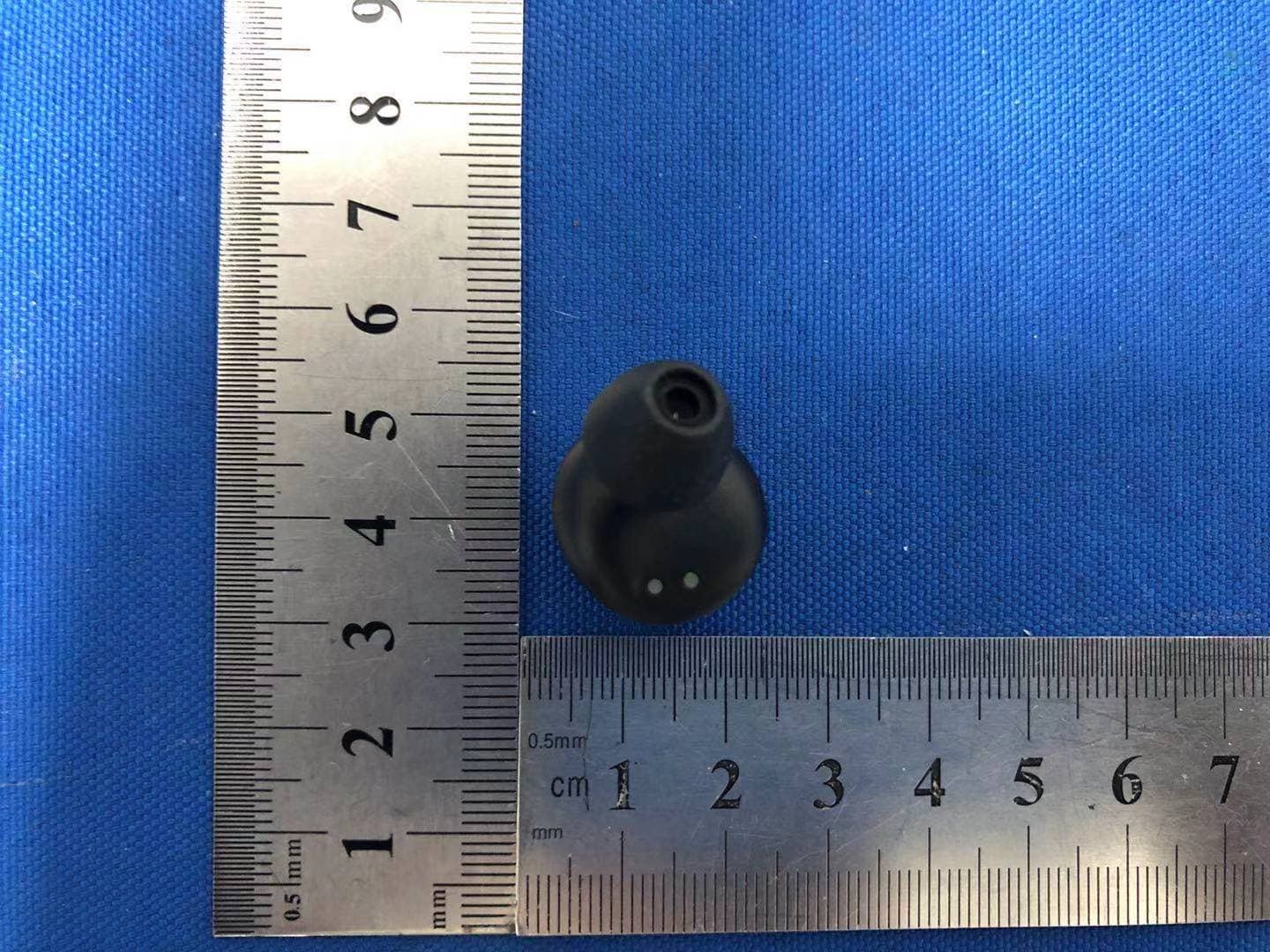
2ASLT-V6R
Apr 29, 2021TWS Bluetooth headset
Equipment Class
DSS - Part 15 Spread Spectrum Transmitter