2ASYV-K-LD224GHz digital radar transceiver
RFbeam Microwave GmbH
Click to zoom
Application Details
- Equipment Class
- FDS - Part 15 Field Disturbance Sensor
- Date of Grant
- Feb 18, 2020
- Application Purpose
- Original Equipment
- Date of Application
- Feb 18, 2020
- Equipment Note
- 24GHz digital radar transceiver
- Frequency Range
- 24125.00000000 - 24125.00000000
- Company
- RFbeam Microwave GmbH
- Country
- Switzerland
Documents & Files
Document Text
Text extracted from the exhibit documents filed with the FCC. Open a document above to read the original.
Users Manual
© RFbeam Microwave GmbH | Schuppisstrasse 7 | CH-9016 St. Gallen | www.rfbeam.ch | K-LD 2 | data sheet 02 / 2020 – Revision C | Page 1 / 25 –Small and low cost digital 24 GHz radar motion detector –Detection distance up to 15m (human) 30m (cars) –High immunity against interferences –Integrated FFT signal processing with digital outputs –Sensitivity and hold time can be set using analogue inputs –Advanced detection data read-out over serial interface –Wide power supply range from 3.2 to 5.5V –2 × 4 patch antenna with 80° / 34° beam aperture –General movement detection applications –Door opener –Illumination of advertising boards –Touch free switches –Security systems –Indoor and outdoor lighting control applications –Object speed measurement systems –Industrial sensors The K-LD2 is a fully digital and low cost radar movement detector. The digital structure makes it very easy to use in any stand-alone or MCU based application where a movement detection or speed measurement is required. The sensor includes a 2 × 4 patch radar front-end with an asymme - trical beam and a powerful signal processing unit with two digital outputs for signal detection information. The sensitivity and the hold time are adjustable using analogue inputs with potentiometers. The serial interface features a powerful command set to read-out advan - ced detection data or to fully customize the detection algorithm. There is no need to write own signal processing algorithms or handle small and noisy signals. This module contains every thing that is necessary to build a simple, yet reliable movement detector. A very small footprint of 25 × 25 × 6.5 mm gives maximum flexibility in the product development process. A powerful evaluation kit (K-LD2-EVAL) with signal visualization on a PC is available. Features Applications Description DATA SHEET K-LD 2 radar transceiver Figure 1: K-LD2 block diagram Tx Rx signal processing unit voltage regulator detect miscellaneous serial interface sensitivityhold time 24.125 GHz K-LD2 Block Diagram PRODUCT INFORMATION © RFbeam Microwave GmbH | Schuppisstrasse 7 | CH-9016 St. Gallen | www.rfbeam.ch | K-LD 2 | data sheet 02 / 2020 – Revision C | Page 2 / 25 CHARACTERISTICS ParameterConditions / NotesSymbolMinTy pMaxUnit Operating Conditions Supply voltageV cc 3.25.5V RMS currentI RMS 55mA Peak currentI peak 65mA Operating temperatureT op -20+85°C Storage temperatureT st -20+105°C Relative humidityNon-condensing, given by designRH1090% Transmitter Transmitter frequencyT amb = -20 ° C .. + 85 ° Cf TX 24.05024.250GHz Frequency drift vs temperatureV cc = 3.3 V∆ f TX 0.06MHz / ° C Output powerEIRPP TX +12dBm Spurious emissionAccording to ETSI 300 440P Spur -30dBm Receiver LNA gainG LNA 20dB Mixer Conversion lossf IF = 1 kHzD mixer 6dB Antenna gainf TX = 24.125 GHzG Ant 8.6dBi Receiver sensitivityf IF = 500 Hz, B = 1 kHz, S / N = 6dBP RX -112dBm Overall sensitivityf IF = 500 Hz, B = 1 kHz, S / N = 6dBD system -127dBc Max. Detection distance σ = 1 m ² ( Person ) R20m Signal Processing Modulationnone Velocity processing256 point FFT Sample ratef sample 1.2812.8kHz Speed rangeDepending on sampling frequencyr speed 0143km / h Response timeDepending on sampling frequency and FFT average feature t detect 20400ms Antenna Horizontal –3dB beamwidthE-Plane W φ 80° Vertical –3dB beamwidthH-Plane W θ 34° Horiz. Sidelobe suppression D φ -12-20dB Vertical sidelobe suppression D θ -12-20dB Interface Digital Output high level voltageV OH 2.12.6V Digital Output low level voltageV OL 0.30.64V Digital Input high level voltageV IH 2.03.3V Digital Input low level voltageV IL -0.30.8V Digital I/O source/sink currentI OH, I OL -2020mA Analogue Input levelV Ain 03V Analogue Input impedanceZ in 200kΩ Body Outline Dimensions25 × 25 × 6.5mm³ Weight6.5g Connector8 pin 2.54 mm ESD rating Electrostatic dischargeHuman body model class 1CV ESD 2000V © RFbeam Microwave GmbH | Schuppisstrasse 7 | CH-9016 St. Gallen | www.rfbeam.ch | K-LD 2 | data sheet 02 / 2020 – Revision C | Page 3 / 25 TABLE OF CONTENTS Product Information ............................1 Features .........................................1 Applications ......................................1 Description .......................................1 Block Diagram ....................................1 Characteristics ..................................2 Antenna Diagram Characteristics ............5 Pin Configuration and Functions .............5 Theory of Operation ............................6 Overview .........................................6 Sampling and FFT calculation ......................7 Start up time .....................................9 Threshold generation ..............................9 Detection algorithm ..............................10 Reaction Time ...................................10 Application Information ......................11 Stand-alone Operation ...........................11 Speed measurement .............................11 Host driven Operation ............................11 Speed limitation and ranging ......................12 Micro detection ..................................12 FFT filter ........................................13 Adjust hold time and sensitivity ...................14 Serial Interface ..................................14 Command Set Description ..................15 Command Classes ...............................15 Command Format ...............................15 Error messages ..................................15 Command List ...................................16 © RFbeam Microwave GmbH | Schuppisstrasse 7 | CH-9016 St. Gallen | www.rfbeam.ch | K-LD 2 | data sheet 02 / 2020 – Revision C | Page 4 / 25 Integrators Information.......................21 Installation Instruction ............................21 United States (FCC) and Canada (ISED) ...........22 Europe (CE-RED) ................................23 Outline Dimensions ...........................24 Order Information .............................24 Revision History .......…
Text truncated - open the document above for the full version.
Cover Letter(s)
Long/Short-term Confidentiality Request PHOENIX TESTLAB GmbH Date: 14 January 2020 Product Certification Königswinkel 10 D 32825 Blomberg FCC ID: 2ASYV-K-LD2 To Whom It May Concerns, Pursuant to sections 0.457(d) and 0.459 of CFR 47 and to avoid premature release of sensitive information prior to marketing or release of the product to the public, we hereby request long-term confidential treatment of information accompanying this application as outlined below: ☒ Schematics ☒ Parts List ☐ Block Diagram ☐ Tune-Up Info ☐ Operational Description In addition we hereby request the following exhibits contained in this application to be temporarily (short-term confidentiality) withheld from the public disclosure ☐ for an initial period of days ☒ until: 06/13/2020 ☐ not applicable ☒ External Photos ☒ Test Setup Photos ☒ Internal Photos ☐ Users Manual The above materials contain trade secrets and proprietary information not customarily released to the public. The public disclosure of these matters might be harmful to the applicant and provide unjustified benefits to its competitors. The applicant understands that pursuant to rule 0.457(d), disclosure of this application and all accompanying documentation will not be made before the date of the GRANT for this application. If you have any questions, please feel free to contact me. Yours sincerely, Signatory Horst Dreinert Graduated Approval Engineer
Cover Letter(s)
PHOENIX TESTLAB GmbH Date: 18 February 2020 Product Certification Königswinkel 10 D 32825 Blomberg Attn: Reviewing Engineer Subject: REQUEST FOR FCC MODULAR TRANSMITTER APPROVAL FCC ID: 2ASYV-K-LD2 To Whom It May Concern: We, (applicant name), hereby request ☒ a modular / ☐ limited modular approval. In CFR47 §15.212 “Modular Transmitters” and KDB 996369 D01 “Module Equip Auth Guide” there are following eight numbered requirements defined: 1. The radio elements must have the radio frequency circuitry shielded. Physical components and tuning capacitor(s) may be located external to the shield, but must be on the module assembly. This request is fulfilled. 2. The modular transmitter must have buffered modulation/data inputs (if such inputs are provided) to ensure that the module will comply with part 15 requirements under conditions of excessive data rates or over-modulation. This request is fulfilled. 3. The modular transmitter must have its own power supply regulation on the module. This request is fulfilled. 4. The module must contain a permanently attached antenna, or contain a unique antenna connector, and be marketed and operated only with specific antenna(s), per §§ 15.203, 15.204(b), 15.204(c), 15.212(a), 2.929(b). This request is fulfilled, the antennas are on the module. 5. The module must demonstrate compliance in a stand-alone configuration. This request is fulfilled. 6. The modular transmitter must be equipped with either a permanently affixed label or must be capable of electronically displaying its FCC identification number (KDB 784748). This request is fulfilled. 7. The modular transmitter must comply with any specific rule or operating requirements applicable to the transmitter and the manufacturer must provide adequate instructions along with the module to explain any such requirements. This request is fulfilled. 8. The modular transmitter must comply with any applicable RF exposure requirements in its final configuration. This request is fulfilled. Yours sincerely, Signatory PHOENIX TESTLAB GmbH Horst Dreinert, Graduated Approval Engineer
External Photos
Annex B External photographs Examiner:Thomas KÜHNReport Number: F181710E2 Date of issue: 11.06.2019Order Number: 18-111710page 1 of 2 181710_2.jpg: K-LC6, front view Annex B External photographs Examiner:Thomas KÜHNReport Number: F181710E2 Date of issue: 11.06.2019Order Number: 18-111710page 2 of 2 181710_5.jpg: K-LC6, rear view
ID Label/Location Info
RFbeam Microwave GmbH K-LD2 digital radar transceiver Label and Location © RFbeam Microwave GmbH, Schuppisstrasse 7, CH-9016 St. Gallen, www.rfbeam.ch Page 1/1 Label Design Label Location Permanently on the backside and in the middle of the shield cover. RFbeam Microwave GmbH K-LD2 K-LD2-RFB-00H-02 Lot: 1950 IC: 24358-KLD2 FCC ID: 2ASYV-K-LD2 RFbeam Microwave GmbH K-LD2 K-LD2-RFB-00H-02 Lot: 1950 IC: 24358-KLD2 FCC ID: 2ASYV-K-LD2
Internal Photos
Annex C Internal photographs Examiner:Thomas KÜHNReport Number: F181710E2 Date of issue: 11.06.2019Order Number: 18-111710page 1 of 2 181710_7.jpg: K-LD2, rear view (shielding removed) Annex C Internal photographs Examiner:Thomas KÜHNReport Number: F181710E2 Date of issue: 11.06.2019Order Number: 18-111710page 2 of 2 181710_8.jpg: K-LD2, PCB, rear view
Operational Description
© RFbeam Microwave GmbH | Schuppisstrasse 7 | CH-9016 St. Gallen | www.rfbeam.ch | K-LD 2 | data sheet 02 / 2020 – Revision C | Page 1 / 25 –Small and low cost digital 24 GHz radar motion detector –Detection distance up to 15m (human) 30m (cars) –High immunity against interferences –Integrated FFT signal processing with digital outputs –Sensitivity and hold time can be set using analogue inputs –Advanced detection data read-out over serial interface –Wide power supply range from 3.2 to 5.5V –2 × 4 patch antenna with 80° / 34° beam aperture –General movement detection applications –Door opener –Illumination of advertising boards –Touch free switches –Security systems –Indoor and outdoor lighting control applications –Object speed measurement systems –Industrial sensors The K-LD2 is a fully digital and low cost radar movement detector. The digital structure makes it very easy to use in any stand-alone or MCU based application where a movement detection or speed measurement is required. The sensor includes a 2 × 4 patch radar front-end with an asymme - trical beam and a powerful signal processing unit with two digital outputs for signal detection information. The sensitivity and the hold time are adjustable using analogue inputs with potentiometers. The serial interface features a powerful command set to read-out advan - ced detection data or to fully customize the detection algorithm. There is no need to write own signal processing algorithms or handle small and noisy signals. This module contains every thing that is necessary to build a simple, yet reliable movement detector. A very small footprint of 25 × 25 × 6.5 mm gives maximum flexibility in the product development process. A powerful evaluation kit (K-LD2-EVAL) with signal visualization on a PC is available. Features Applications Description DATA SHEET K-LD 2 radar transceiver Figure 1: K-LD2 block diagram Tx Rx signal processing unit voltage regulator detect miscellaneous serial interface sensitivityhold time 24.125 GHz K-LD2 Block Diagram PRODUCT INFORMATION © RFbeam Microwave GmbH | Schuppisstrasse 7 | CH-9016 St. Gallen | www.rfbeam.ch | K-LD 2 | data sheet 02 / 2020 – Revision C | Page 2 / 25 CHARACTERISTICS ParameterConditions / NotesSymbolMinTy pMaxUnit Operating Conditions Supply voltageV cc 3.25.5V RMS currentI RMS 55mA Peak currentI peak 65mA Operating temperatureT op -20+85°C Storage temperatureT st -20+105°C Relative humidityNon-condensing, given by designRH1090% Transmitter Transmitter frequencyT amb = -20 ° C .. + 85 ° Cf TX 24.05024.250GHz Frequency drift vs temperatureV cc = 3.3 V∆ f TX 0.06MHz / ° C Output powerEIRPP TX +12dBm Spurious emissionAccording to ETSI 300 440P Spur -30dBm Receiver LNA gainG LNA 20dB Mixer Conversion lossf IF = 1 kHzD mixer 6dB Antenna gainf TX = 24.125 GHzG Ant 8.6dBi Receiver sensitivityf IF = 500 Hz, B = 1 kHz, S / N = 6dBP RX -112dBm Overall sensitivityf IF = 500 Hz, B = 1 kHz, S / N = 6dBD system -127dBc Max. Detection distance σ = 1 m ² ( Person ) R20m Signal Processing Modulationnone Velocity processing256 point FFT Sample ratef sample 1.2812.8kHz Speed rangeDepending on sampling frequencyr speed 0143km / h Response timeDepending on sampling frequency and FFT average feature t detect 20400ms Antenna Horizontal –3dB beamwidthE-Plane W φ 80° Vertical –3dB beamwidthH-Plane W θ 34° Horiz. Sidelobe suppression D φ -12-20dB Vertical sidelobe suppression D θ -12-20dB Interface Digital Output high level voltageV OH 2.12.6V Digital Output low level voltageV OL 0.30.64V Digital Input high level voltageV IH 2.03.3V Digital Input low level voltageV IL -0.30.8V Digital I/O source/sink currentI OH, I OL -2020mA Analogue Input levelV Ain 03V Analogue Input impedanceZ in 200kΩ Body Outline Dimensions25 × 25 × 6.5mm³ Weight6.5g Connector8 pin 2.54 mm ESD rating Electrostatic dischargeHuman body model class 1CV ESD 2000V © RFbeam Microwave GmbH | Schuppisstrasse 7 | CH-9016 St. Gallen | www.rfbeam.ch | K-LD 2 | data sheet 02 / 2020 – Revision C | Page 3 / 25 TABLE OF CONTENTS Product Information ............................1 Features .........................................1 Applications ......................................1 Description .......................................1 Block Diagram ....................................1 Characteristics ..................................2 Antenna Diagram Characteristics ............5 Pin Configuration and Functions .............5 Theory of Operation ............................6 Overview .........................................6 Sampling and FFT calculation ......................7 Start up time .....................................9 Threshold generation ..............................9 Detection algorithm ..............................10 Reaction Time ...................................10 Application Information ......................11 Stand-alone Operation ...........................11 Speed measurement .............................11 Host driven Operation ............................11 Speed limitation and ranging ......................12 Micro detection ..................................12 FFT filter ........................................13 Adjust hold time and sensitivity ...................14 Serial Interface ..................................14 Command Set Description ..................15 Command Classes ...............................15 Command Format ...............................15 Error messages ..................................15 Command List ...................................16 © RFbeam Microwave GmbH | Schuppisstrasse 7 | CH-9016 St. Gallen | www.rfbeam.ch | K-LD 2 | data sheet 02 / 2020 – Revision C | Page 4 / 25 Integrators Information.......................21 Installation Instruction ............................21 United States (FCC) and Canada (ISED) ...........22 Europe (CE-RED) ................................23 Outline Dimensions ...........................24 Order Information .............................24 Revision History .......…
Text truncated - open the document above for the full version.
Test Report
Königswinkel 10 32825 Blomberg, Germany Phone: +49 (0) 52 35 / 95 00-0 Fax:+49 (0) 52 35 / 95 00-10 [email protected] www.phoenix-testlab.de Test Report Report Number: F181710E2 Equipment under Test (EUT): K-LD2 Applicant: RFbeam Microwave GmbH Manufacturer: RFbeam Microwave GmbH Test engineer: Thomas KÜHNReport Number:F181710E2 Date of issue: 11.06.2019Order Number:18-111710page 2 of 34 REFERENCES [1] ANSI C63.10-2013 American National Standard for Methods of Measuring of Radio-Noise Emissions from Low-Voltage Electrical and Electronic Equipment in the Range of 9 kHz to 40 GHz. [2] FCC CFR 47 Part 15 Radio Frequency Devices [3] RSS-210 Issue 9 (August 2016)Licence-exempt Radio Apparatus: Category I Equipment [4] RSS-Gen Issue 5 (March 2019) Amendment 1 General Requirements for Compliance of Radio Apparatus TEST RESULT The requirements of the tests performed as shown in the overview (clause 4) were fulfilled by the equipment under test. The complete test results are presented in the following. RESERVATION This test report is only valid in its original form. Any reproduction of its contents in extracts without written permission of the accredited test laboratory PHOENIX TESTLAB GmbH is prohibited. The test results herein refer only to the tested sample. PHOENIX TESTLAB GmbH is not responsible for any generalisations or conclusions drawn from these test results concerning further samples. Any modification of the tested samples is prohibited and leads to the invalidity of this test report. Each page necessarily contains the PHOENIX TESTLAB Logo and the TEST REPORT NUMBER. Test engineer: Thomas KÜHN 11.06.2019 NameSignatureDate Authorized reviewer: Michael DINTER 11.06.2019 Name Signature Date Test engineer: Thomas KÜHNReport Number:F181710E2 Date of issue: 11.06.2019Order Number:18-111710page 3 of 34 Contents:Page 1Identification ........................................................................................................................................4 1.1Applicant ........................................................................................................................................4 1.2Manufacturer ..................................................................................................................................4 1.3Test laboratory ...............................................................................................................................4 1.4EUT (Equipment Under Test) .........................................................................................................5 1.5Technical data of equipment ...........................................................................................................5 1.6Dates .............................................................................................................................................6 2Operational states ...............................................................................................................................6 3Additional Information..........................................................................................................................7 4Overview .............................................................................................................................................7 5Test results .........................................................................................................................................8 5.1Bandwidth ......................................................................................................................................8 5.1.1Method of measurement (bandwidth) ....................................................................................8 5.2Test results (20 dB bandwidth) .......................................................................................................9 5.2.1Test results (99 % bandwidth) ............................................................................................ 10 5.3Band-edge compliance ................................................................................................................. 11 5.3.1Method of measurement (band-edge compliance) .............................................................. 11 5.3.2Test results (band-edge compliance) .................................................................................. 12 5.4Radiated emissions ...................................................................................................................... 14 5.4.1Method of measurement (radiated emissions)..................................................................... 14 5.4.3Test results (radiated emissions) ........................................................................................ 23 5.4.3.1Preliminary radiated emission measurement (10 MHz to 100 GHz) ................................ 23 5.4.3.2Final radiated emission measurement (10 MHz to 30 MHz)............................................ 29 5.4.3.3Final radiated emission measurement (30 MHz to 1 GHz) .............................................. 29 5.4.3.4Final radiated emission measurement (1 GHz to 100 GHz) ............................................ 30 5.5Conducted emissions on power supply lines (150 kHz to 30 MHz) ................................................ 31 5.5.1Method of measurement ..................................................................................................... 31 5.5.2Test results (conducted emissions on power supply lines) .................................................. 32 6Test equipment and ancillaries used for tests .................................................................................... 33 7Test site validation ............................................................................................................................ 34 8Report history..............................................................................................…
Text truncated - open the document above for the full version.
Test Setup Photos
Annex A Test setup photographs Examiner:Thomas KÜHNReport Number: F181710E2 Date of issue: 11.06.2019Order Number: 18-111710page 1 of 7 181710_r.jpg: K-LD2, test setup fully anechoic chamber Annex A Test setup photographs Examiner:Thomas KÜHNReport Number: F181710E2 Date of issue: 11.06.2019Order Number: 18-111710page 2 of 7 181710_k.jpg: K-LD2, test setup fully anechoic chamber Annex A Test setup photographs Examiner:Thomas KÜHNReport Number: F181710E2 Date of issue: 11.06.2019Order Number: 18-111710page 3 of 7 181710_l.jpg: K-LD2, test setup fully anechoic chamber Annex A Test setup photographs Examiner:Thomas KÜHNReport Number: F181710E2 Date of issue: 11.06.2019Order Number: 18-111710page 4 of 7 181710_m.jpg: K-LD2, test setup fully anechoic chamber Annex A Test setup photographs Examiner:Thomas KÜHNReport Number: F181710E2 Date of issue: 11.06.2019Order Number: 18-111710page 5 of 7 181710_p.jpg: K-LD2, test setup fully anechoic chamber Annex A Test setup photographs Examiner:Thomas KÜHNReport Number: F181710E2 Date of issue: 11.06.2019Order Number: 18-111710page 6 of 7 181710_n.jpg: K-LD2, test setup fully anechoic chamber Annex A Test setup photographs Examiner:Thomas KÜHNReport Number: F181710E2 Date of issue: 11.06.2019Order Number: 18-111710page 7 of 7 181710_q.jpg: K-LD2, test setup shielded chamber
Contact Information
Applicant
Leon Audergon
Test Firm
PHOENIX TESTLAB GmbHHolger Bentje
Technical Specifications
| # | Rule Parts | Frequency Range | Power Output |
|---|---|---|---|
| 1 | 15.245 | 24.13 GHz - 24.13 GHz | - |
Other Applications from RFbeam Microwave GmbH
2ASYV-K-MD7
Jul 02, 2026Digital Radar Transceiver
Equipment Class
FDS - Part 15 Field Disturbance Sensor2ASYV-KIS-SHLK
Dec 04, 2025Distance and velocity measurement sensor
Equipment Class
FDS - Part 15 Field Disturbance Sensor2ASYV-K-LD2-FLK
Mar 12, 202424 GHz Doppler Radar
Equipment Class
DXX - Part 15 Low Power Communication Device Transmitter
2ASYV-PHI-1
Mar 07, 2024Digital K-Band Radar Sensor
Equipment Class
DXX - Part 15 Low Power Communication Device Transmitter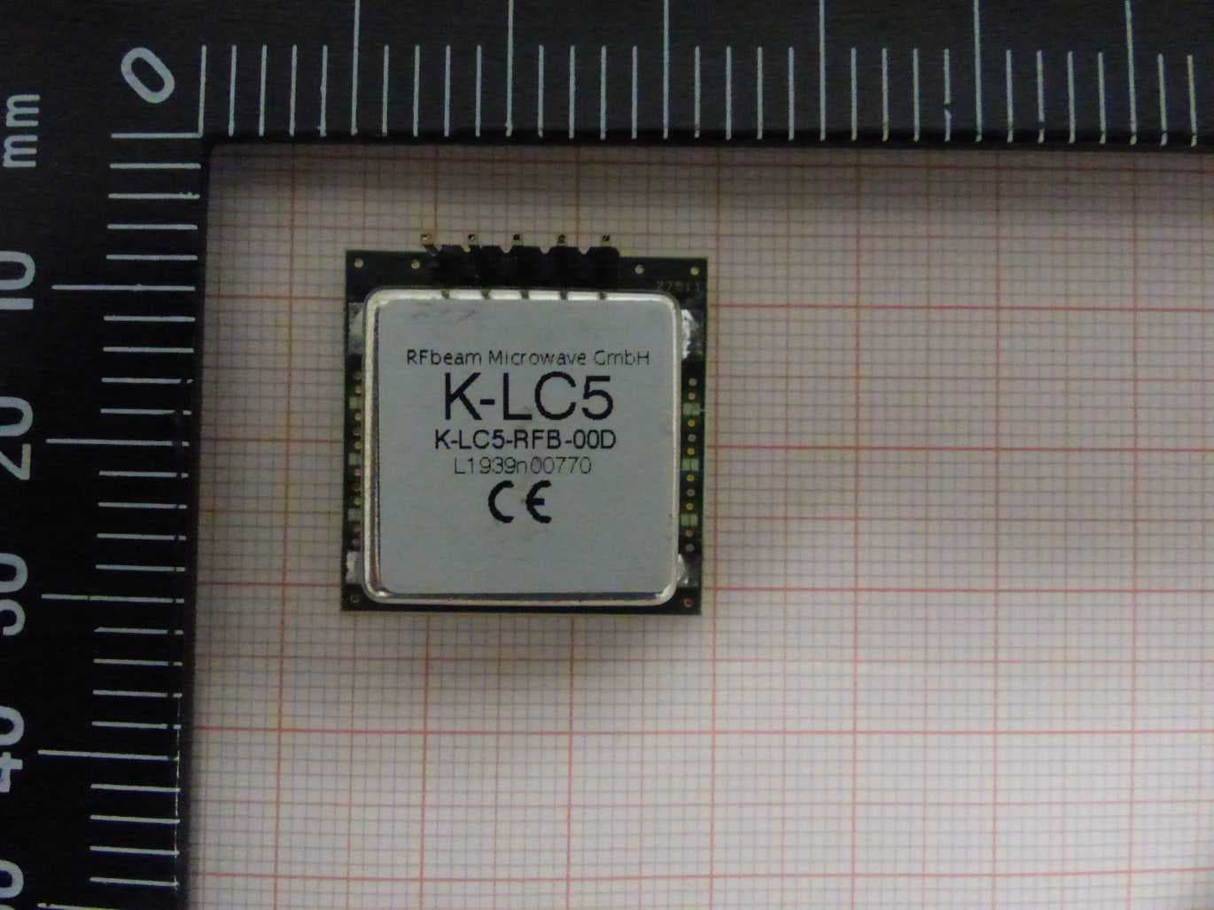
2ASYV-K-LC5
Apr 18, 202124GHz analog radar transceiver
Equipment Class
DXT - Part 15 Low Power Transceiver, Rx Verified