2ASYV-PHI-1Digital K-Band Radar Sensor
RFbeam Microwave GmbH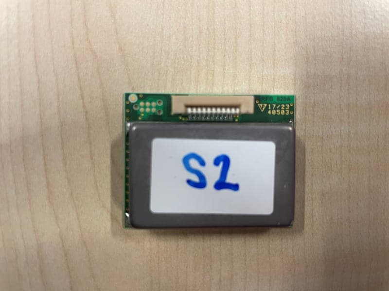
Click to zoom
Application Details
- Equipment Class
- DXX - Part 15 Low Power Communication Device Transmitter
- Date of Grant
- Mar 07, 2024
- Application Purpose
- Original Equipment
- Date of Application
- Mar 07, 2024
- Equipment Note
- Digital K-Band Radar Sensor
- Frequency Range
- 24116.00000000 - 24230.00000000
- Company
- RFbeam Microwave GmbH
- Country
- Switzerland
Documents & Files
Document Text
Text extracted from the exhibit documents filed with the FCC. Open a document above to read the original.
Users Manual
Phi-1 Integration instructions for host product manufacturers According to KDB 996369 D03 Page 1/1 2.2 List of applicable FCC rules The applicable FCC rules are listed in the section integrators information of the product datasheet: “This module meets the title 47 of the Code of Federal Regulations, part 15 section 15.245 for intentional radiators operating in the 24.00 to 24.25 GHz band.“ 2.3 Summarize the specific operational use conditions The product has integrated patch antennas. There are no specific operational use conditions. 2.4 Limited module procedures The product is granted as a single modular transmitter. 2.5 Trace antenna designs The product has integrated patch antennas. 2.6 RF exposure considerations The following is included in the section integrators information of the product datasheet: “The radiated output power of the device is far below the FCC radio frequency exposure limits. Nevertheless, the device should be used in such a manner that the potential for human contact during normal operation is minimized.” 2.7 Antennas The module has integrated patch antennas. 2.8 Label and compliance information The following is included in the section integrators information of the product datasheet: “If the label of the module is not visible from the outside of the end product, it must include the following texts on the label of the host product: FCC: Contains FCC ID: 2ASYV-PHI-1 In addition to marking the product with the appropriate ID’s, the end product shall bear the following statement in a conspicuous location on the label or alternatively in the user manual: This device complies with Part 15 of the FCC Rules. Operation is subject to the following two conditions: (1) this device may not cause harmful interference, and (2) this device must accept any interference received, including interference that may cause undesired operation.” 2.9 Information on test modes and additional testing requirements The following is included in the section integrators information of the product datasheet: “Testing for the modular approval has been performed with the 10m range setting for all available frequency channels which represents the maximum TX emission configuration with the complete used bandwidth. This setup can easily be used by the customer for certification purposes.” 2.10 Additional testing, Part 15 Subpart B disclaimer The following warning is included in the section integrators information of the product datasheet: “The OEM integrator is responsible for the final compliance to any other FCC rules that apply to the host not covered by the modular transmitter grant of certification.”
Users Manual
Phi-1 Datasheet 01.03.2024 / V01 Page 1/5 1 Overview Top View Bottom View 1.1 Operational description The Phi-1 represents a state-of-the-art digital Doppler radar transceiver equipped with integrated planar patch antennas. At its core lies an advanced RF front end featuring dual transmit and dual receive channels, complemented by a dedicated IF amplifier section. Steering these components is a microcontroller unit (MCU) responsible for orchestrating RF front end operations and sampling IF channels via integrated analog-to-digital converters. The resultant sampled data is accessible to a host system through a serial interface, facilitating seamless integration into further signal processing pipelines. Leveraging the Doppler frequencies it generates, the Phi-1 excels in the precise detection and speed measurement of moving objects within its antenna beam. Additionally, the inclusion of FSK modulation enhances its functionality, enabling accurate distance measurement to these dynamic targets. Thanks to its dual transmitting and receiving antenna setup, the Phi-1 enables precise determination of azimuth and elevation angles associated with detected objects. 1.2 Block diagram Phi-1 Datasheet 01.03.2024 / V01 Page 2/5 1.3 Characteristics Parameter Conditions / Notes Symbol Min Typ Max Unit Operating conditions Supply voltage V cc 3.2 5.5 V Supply current I cc 25 160 250 mA Operating temperature T Op -40 +85 °C Storage temperature T St -40 +105 °C Transmitter Transmitter frequency T amb =-40°C .. +85°C f TX 24.050 24.250 GHz Output power EIRP P TX 7 dBm Spurious emissions According to ETSI 300 440 P Spur -30 dBm Signal processing Modulation FSK Processing 256 point complex FFT Sample rate f Sample 1119 2238 Hz Speed range Depending on sampling frequency R Speed 0.1 25 km/h Receiver LNA gain G LNA 19 dB Mixer conversion loss f IF =1kHz D mixer 10 dB Antenna gain f TX =24.15GHz G Ant 5.6 dBi Receiver sensitivity f IF =500Hz, B=1kHz, S/N=6dB P RX -109 dBm Overall sensitivity f IF =500Hz, B=1kHz, S/N=6dB D system -124 dBc Detection distance σ=1 m 2 (Person) R 10 m Antenna Horizontal –3dB beam width E-Plane W φ 86 ° Vertical –3dB beam width H-Plane W θ 63 ° Horiz. side lobe suppression D φ -12 -20 dB Vertical side lobe suppression D θ -12 -20 dB Interface Digital output high level voltage V OH@8mA 2.4 3 V Digital output low level voltage V OL@8mA 0 0.4 V Digital output high level voltage V OH@20mA 1.7 3 V Digital output low level voltage V OL@20mA 0 1.3 V Digital input high level voltage V IH 1.7 4 V Digital input low level voltage V IL -0.3 1.3 V Digital I/O source/sink current I OH , I OL -20 20 mA Body Outline dimensions 38 x 30 x 7 mm 3 Weight 10 g Connector 10-pin FPC connector ESD rating Electrostatic discharge Human body model class 2 V ESD 2000 V Phi-1 Datasheet 01.03.2024 / V01 Page 3/5 1.4 Antenna pattern The 90° vector is aligned with the antenna boresight axis. Radiation direction elevation Radiation direction azimuth 0° 90° 180° 0° 90° 180° Phi-1 Datasheet 01.03.2024 / V01 Page 4/5 2 Integrators Information 2.1 Installation Instruction 2.1.1 Mechanical enclosure It is possible to hide the sensor behind a so called radome (short for radar dome) to protect it from environmental influences or to simply integrate it in the case of the end product. A radar sensor can see trough different types of plastic and glass of any colour as long as it is not metallized. This allows for a very flexible design of the housing as long as the rules below are observed. • Cover must not be metallic. • No plastic coating with colors containing metallic or carbon particles. • Distance between cover and front of Radar sensor should be >= 6.2mm • Cover thickness is very important and depends on the used material. Examples can be found in the application note "AN-03-Radome". • Vibrations of the Radar antenna relatively to the cover should be avoided, because this generates signals that can trigger the output • The cover material can act as a lens and focus or disperse the transmitted waves. Use a constant material thickness within the area used for transmission to minimize the effect of the radome to the radiated antenna pattern. Note Detailed information about the calculation and thickness for different cover materials can be found in the application note “AN-03-Radome”. Phi-1 Datasheet 01.03.2024 / V01 Page 5/5 2.2 United States (FCC) This module has been granted modular approval for fixed and/or mobile applications by FCC. Testing for the modular approval has been performed with the 10m range setting for all available frequency channels which represents the maximum TX emission configuration with the complete used bandwidth. This setup can easily be used by the customer for certification purposes. This module meets the title 47 of the Code of Federal Regulations, part 15 section 15.249 for intentional radiators operating in the 24.00 to 24.25 GHz band. Note Modification to this product will void the users’ authority to operate this equipment. Warning The OEM integrator is responsible for the final compliance to any other FCC rules that apply to the host not covered by the modular transmitter grant of certification. 2.2.1 Labelling and user information requirements If the label of the module is not visible from the outside of the end product, it must include the following texts on the label of the host product: Contains FCC ID: 2ASYV-PHI-1 In addition to marking the product with the appropriate ID’s, the end product shall bear the following statement in a conspicuous location on the label or alternatively in the user manual: This device complies with Part 15 of the FCC Rules. Operation is subject to the following two conditions: (1) this device may not cause harmful interference, and (2) this device must accept any interference received, including interference that may cause undesired operation. 2.2.2 RF Exposure The radiated output power of the device is far below the FCC radio frequency exposure limits. Never…
Text truncated - open the document above for the full version.
External Photos
Annex A No.1-7290/23-01-01 February 20, 2024 DescriptionExternal photographs of EUT This document is electronically signed and valid without handwritten signature. Public keys for verification of the electronic signatures can be requested at the testing laboratory. Authorized Meheza Walla Lab Manager Radio Labs cetecom advanced GmbH Untertürkheimer Str. 6-10, 66117 Saarbrücken Document No. 1-7290/23-01-01 Release 1 - Page 1 of 2 Photo 1 - END OF DOCUMENT - cetecom advanced GmbH Untertürkheimer Str. 6-10, 66117 Saarbrücken Document No. 1-7290/23-01-01 Release 1 - Page 2 of 2
ID Label/Location Info
Phi-1 Label and Location 28.02.2024 / UG Page 1/1 Label Design Label Location Permanently on the backside and in the middle of the shield cover. RFbeam Microwave GmbH Phi-1-00H-01 L2408n00001 FCC ID: 2ASYV-PHI-1 RFbeam Microwave GmbH Phi-1-00H-01 L2408n00001 FCC ID: 2ASYV-PHI-1 Phi-1
Internal Photos
Annex B No.1-7290/23-01-01 February 20, 2024 DescriptionInternal photographs of EUT This document is electronically signed and valid without handwritten signature. Public keys for verification of the electronic signatures can be requested at the testing laboratory. Authorized Meheza Walla Lab Manager Radio Labs cetecom advanced GmbH Untertürkheimer Str. 6-10, 66117 Saarbrücken Document No. 1-7290/23-01-01 Release 1 - Page 1 of 2 Photo 1 Photo 2 - END OF DOCUMENT - cetecom advanced GmbH Untertürkheimer Str. 6-10, 66117 Saarbrücken Document No. 1-7290/23-01-01 Release 1 - Page 2 of 2
RF Exposure Info
© cetecom advanced GmbH Page 1 of 2 RF Exposure Evaluation according to KDB 447498 D01 v06 Report identification number: 1-7290_23-01-04_TR1-R02_MPE_FCC Certification numbers and labeling requirements FCC ID 2ASYV-PHI-1 This test report is electronically signed and valid without handwritten signature. For verification of the electronic signatures, the public keys can be requested at the testing laboratory. Document authorised: Alexander Hnatovskiy Eric Tuettmann Lab Manager Testing Manager Radio Labs Radio Labs Report no.: 1-7290_23-01-04_TR1-R02 © cetecom advanced GmbH Page 2 of 2 1. MPE at given distance (KDB 447498 D01 General RF Exposure Guidance v06) Equation from page 18 of OET Bulletin 65, Edition 97-01 S = PG / 4 π R 2 where: S = Power density P = Power input to the antenna G = Antenna gain R = Distance to the center of radiation of the antenna PG = Output Power including antenna gain The table below is excerpted from Table 1B of 47 CFR 1.1310 titled “Limits for Maximum Permissible Exposure (MPE), Limits for General Population/Uncontrolled Exposure” Frequency Range (MHz) Power Density (mW/cm 2 ) Averaging Time (minutes) 300 -1500 f/1500 30 1500 - 100000 1.0 30 where f = Frequency (MHz) 2. EUT technologies Declared minimum safety distance: 20 cm f Min f Max #P E RP P E IRP P RF E xp S Resu lt S Limit % Radar 24GHz 24000 24250AN/A12.812.80.00381.000.38% Output Power [dBm] SRD Technology Frequency [MHz] Reference Power Density [mW /cm²] Share of Limit Referenced Documents: # Results from: A Test Report 1-7290/23-01-02 3. Conclusion This prediction demonstrates the following: The power density levels for FCC at a distance of 20 cm are below the maximum levels allowed by regulations. Conclusion: RF exposure evaluation is not required.
Test Report
BNetzA - CAB - 02/21 - 102 TEST REPORT Test report no.: 1-7290_23-01-02 Testing laboratory Applicant cetecom advanced GmbH Untertuerkheimer Strasse 6 – 10 66117 Saarbruecken / Germany Phone: + 49 681 5 98 - 0 Fax: + 49 681 5 98 - 9075 Internet: https://www.cetecomadvanced.com e-mail: [email protected] Accredited Testing Laboratory: The testing laboratory (area of testing) is accredited according to DIN EN ISO/IEC 17025 (2018-03) by the Deutsche Akkreditierungsstelle GmbH (DAkkS). The accreditation is valid for the scope of testing procedures as stated in the accreditation certificate with the registration number: D-PL-12047-01-00. ISED Testing Laboratory Recognized Listing Number: DE0001 FCC designation number: DE0002 RFbeam Microwave GmbH Schuppisstrasse 7 9016 St. Gallen / SWITZERLAND Phone: +41 7 12 45 33 80 Contact: Ueli Giger e-mail: [email protected] Manufacturer RFbeam Microwave GmbH Schuppisstrasse 7 9016 St. Gallen / SWITZERLAND Test standard/s FCC - Title 47 CFR Part 15 FCC - Title 47 of the Code of Federal Regulations; Chapter I; Part 15 - Radio frequency devices For further applied test standards please refer to section 3 of this test report. Test Item Kind of test item: Digital K-Band Radar Sensor Model name: Phi-1 FCC ID: 2ASYV-PHI-1 Frequency: 24.00 GHz – 24.25 GHz Technology tested: FSK Antenna: Integrated PCB Patch Antenna Power supply: 3.2 V DC to 5.5 V DC by power supply Temperature range: -40°C to +85°C This test report is electronically signed and valid without handwritten signature. For verification of the electronic signatures, the public keys can be requested at the testing laboratory. Test report authorized: Test performed: Thomas Vogler Meheza Walla Lab Manager Lab Manager Radio Labs Radio Labs Test report no.: 1-7290_23-01-02 © cetecom advanced GmbH Page 2 of 72 1 Table of contents 1 Table of contents ....................................................................................................................................... 2 2 General information ................................................................................................................................... 3 2.1 Notes and disclaimer ...................................................................................................................... 3 2.2 Application details .......................................................................................................................... 3 2.3 Test laboratories sub-contracted .................................................................................................... 3 3 Test standard/s, references and accreditations ......................................................................................... 4 4 Reporting statements of conformity – decision rule .................................................................................. 4 5 Test environment ....................................................................................................................................... 5 6 Test item ................................................................................................................................................... 5 6.1 General description ......................................................................................................................... 5 6.2 Additional information .................................................................................................................... 5 7 Description of the test setup ...................................................................................................................... 6 7.1 Shielded semi anechoic chamber .................................................................................................... 7 7.2 Shielded fully anechoic chamber ..................................................................................................... 9 7.3 Radiated measurements > 18 GHz ................................................................................................ 11 7.4 Radiated measurements > 50/85 GHz ........................................................................................... 11 7.5 AC conducted ................................................................................................................................ 13 8 Sequence of testing ................................................................................................................................. 14 8.1 Sequence of testing radiated spurious 9 kHz to 30 MHz ............................................................... 14 8.2 Sequence of testing radiated spurious 30 MHz to 1 GHz ............................................................... 15 8.3 Sequence of testing radiated spurious 1 GHz to 18 GHz................................................................ 16 8.4 Sequence of testing radiated spurious above 18 GHz .................................................................... 17 8.5 Sequence of testing radiated spurious above 50 GHz with external mixers ................................... 18 9 Measurement uncertainty ........................................................................................................................ 19 10 Summary of measurement results ....................................................................................................... 20 11 Additional comments ........................................................................................................................... 21 12 Measurement results ........................................................................................................................... 22 12.1 Bandwidth and frequency stability of the wanted signal ............................................................ 22 12.2 Antenna gain & beam width ....................................................................................................... 42 12.3 Field strength of fundamental emissi…
Text truncated - open the document above for the full version.
Test Setup Photos
Annex D No.1-7290/23-01-01 February 20, 2024 DescriptionTest set-up photographs This document is electronically signed and valid without handwritten signature. Public keys for verification of the electronic signatures can be requested at the testing laboratory. Authorized Meheza Walla Lab Manager Radio Labs cetecom advanced GmbH Untertürkheimer Str. 6-10, 66117 Saarbrücken Document No. 1-7290/23-01-01 Release 1 - Page 1 of 4 Photo 1 Photo 2 cetecom advanced GmbH Untertürkheimer Str. 6-10, 66117 Saarbrücken Document No. 1-7290/23-01-01 Release 1 - Page 2 of 4 Photo 3 Photo 4 cetecom advanced GmbH Untertürkheimer Str. 6-10, 66117 Saarbrücken Document No. 1-7290/23-01-01 Release 1 - Page 3 of 4 Photo 5 Photo 6 - END OF DOCUMENT - cetecom advanced GmbH Untertürkheimer Str. 6-10, 66117 Saarbrücken Document No. 1-7290/23-01-01 Release 1 - Page 4 of 4
Contact Information
Applicant
Leon Audergon
Test Firm
cetecom advanced GmbHGerald Schmidt
Technical Specifications
| # | Rule Parts | Frequency Range | Power Output |
|---|---|---|---|
| 1 | 15C | 24.12 GHz - 24.23 GHz | - |
Other Applications from RFbeam Microwave GmbH
2ASYV-K-MD7
Jul 02, 2026Digital Radar Transceiver
Equipment Class
FDS - Part 15 Field Disturbance Sensor2ASYV-KIS-SHLK
Dec 04, 2025Distance and velocity measurement sensor
Equipment Class
FDS - Part 15 Field Disturbance Sensor2ASYV-K-LD2-FLK
Mar 12, 202424 GHz Doppler Radar
Equipment Class
DXX - Part 15 Low Power Communication Device Transmitter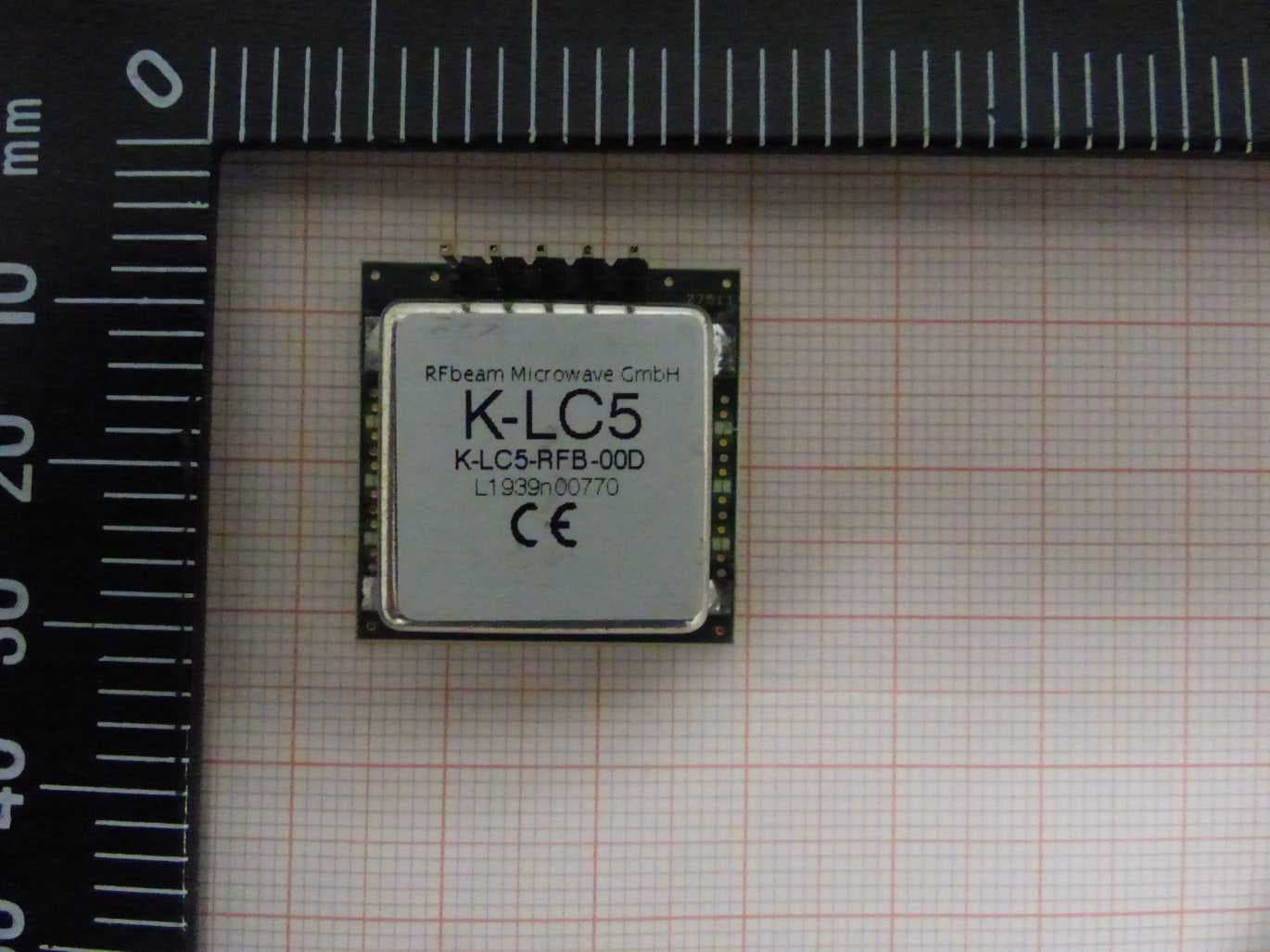
2ASYV-K-LC5
Apr 18, 202124GHz analog radar transceiver
Equipment Class
DXT - Part 15 Low Power Transceiver, Rx Verified
2ASYV-K-LD7
Dec 20, 202024GHz digital radar transceiver
Equipment Class
DXT - Part 15 Low Power Transceiver, Rx Verified