2ASYV-K-LD724GHz digital radar transceiver
RFbeam Microwave GmbH
Click to zoom
Application Details
- Equipment Class
- DXT - Part 15 Low Power Transceiver, Rx Verified
- Date of Grant
- Dec 20, 2020
- Application Purpose
- Original Equipment
- Date of Application
- Dec 20, 2020
- Equipment Note
- 24GHz digital radar transceiver
- Frequency Range
- 24050.00000000 - 24250.00000000
- Company
- RFbeam Microwave GmbH
- Country
- Switzerland
Documents & Files
Document Text
Text extracted from the exhibit documents filed with the FCC. Open a document above to read the original.
Users Manual
Integration instructions for host product manufacturers According to KDB 996369 D03 © RFbeam Microwave GmbH, Schuppisstrasse 7, 9016. St. Gallen, www.rfbeam.ch Page 1/1 2.2 List of applicable FCC rules The applicable FCC rules are listed in the section integrators information of the product datasheet: “This module meets the title 47 of the Code of Federal Regulations, part 15 section 15.249 for intentional radiators operating in the 24.00 to 24.25 GHz band.“ 2.3 Summarize the specific operational use conditions The product has integrated patch antennas. There are no specific operational use conditions. 2.4 Limited module procedures The product is granted as a single modular transmitter. 2.5 Trace antenna designs The product has integrated patch antennas. 2.6 RF exposure considerations The following is included in the section integrators information of the product datasheet: “The radiated output power of the device is far below the FCC radio frequency exposure limits. Nevertheless, the device should be used in such a manner that the potential for human contact during normal operation is minimized.” 2.7 Antennas The module has integrated patch antennas. 2.8 Label and compliance information The following is included in the section integrators information of the product datasheet: “If the label of the module is not visible from the outside of the end product, it must include the following texts on the label of the host product: FCC: Contains FCC ID: 2ASYV-K-LD7 In addition to marking the product with the appropriate ID’s, the end product shall bear the following statement in a conspicuous location on the label or alternatively in the user manual: This device complies with Part 15 of the FCC Rules and with Industry Canada licence-exempt RSS standard(s). Operation is subject to the following two conditions: (1) this device may not cause harmful interference, and (2) this device must accept any interference received, including interference that may cause undesired operation.” 2.9 Information on test modes and additional testing requirements The following is included in the section integrators information of the product datasheet: “Testing for the modular approval has been performed with the 10m range setting for all available frequency channels which represents the maximum TX emission configuration with the complete used bandwidth. This setup can easily be used by the customer for certification purposes.” 2.10 Additional testing, Part 15 Subpart B disclaimer The following warning is included in the section integrators information of the product datasheet: “The OEM integrator is responsible for the final compliance to any other FCC rules that apply to the host not covered by the modular transmitter grant of certification.”
Users Manual
© RFbeam Microwave GmbH | Schuppisstrasse 7 | CH-9016 St. Gallen | www.rfbeam.ch | K-LD7 | data sheet 12 / 2020 – Revision B | Page 1 / 23 PRODUCT INFORMATION –Small and low cost digital 24 GHz radar motion detector –Measures speed, direction, distance and angle of moving objects –Low current consumption –Typical detection distance: 15 m for persons / 30 m for cars –Target list output over serial interface –Integrated FFT signal processing with tracking –4 configurable digital outputs –Power supply range from 3.2 to 5.5 V –3 × 4 patch antenna with 80 °/ 34 ° beam aperture –Distance triggered movement detection applications –Simple gesture recognition –Indoor and outdoor lighting control applications –Pedestrian counting –Traffic counting The K-LD7 is a fully digital low cost Doppler radar that can mea- sure speed, direction, distance and angle of moving objects in front of the sensor. The digital structure and wide power supply range make it very easy to use this sensor in any stand-alone or MCU based application. The sensor includes a 3 × 4 patch antenna radar front-end with an asymmetrical beam and a powerful signal processing unit with four configurable digital outputs for signal detection information. A built-in tracking filter makes the sensor output even easier to use. The serial interface features the possibility to read out a target list with speed, direction, distance and angle information of all moving objects in front of the sensor or to digitally configure the sensors detection parameters. There is no need to write own signal processing algorithms or handle small and noisy signals. This module contains everything what is necessary to build a simple but powerful motion detec- tor with distance and angle information. A very small footprint of 38 × 25 × 13.5 mm gives maximum flexibility in the product develop- ment process. For fast prototyping an evaluation kit (K-LD7-EVAL) is available which features powerful signal visualization on a PC. Features Applications Description data sheet K-LD7 digital radar transceiver Figure 1: Block diagram signal processing unit voltage regulator detect out 1 out 2 out 3 serial interface I Q I Q K-LD7 24.05–24.25 GHz Tx Rx1 Rx2 Block Diagram © RFbeam Microwave GmbH | Schuppisstrasse 7 | CH-9016 St. Gallen | www.rfbeam.ch | K-LD7 | data sheet 12 / 2020 – Revision B | Page 2 / 23 Characteristics ParameterConditions / NotesSymbolMinTy pMaxUnit Operating Conditions Supply voltageV cc 3.25.5V RMS currentDepending on speed range settingI cc 2060mA Peak currentAt start-upI pp 116200mA Operating temperatureT Op -40+85°C Storage temperatureT St -40+105°C Relative humidityNon-condensing, given by designRH10 90 % Transmitter Transmitter frequencyT amb = -40 ° C .. + 85 ° Cf TX 24.05024.250GHz Frequency drift vs. temperature ∆f TX 0.6 MHz/°C Output powerEIRPP TX 610dBm Spurious emissions According to ETSI 300 440P spur -30dBm Receiver LNA gainG LNA 19dB Mixer conversion lossf IF = 1kHzD mixer 10dB Antenna gainf TX = 24.15 GHzG Ant 8.6dBi Receiver sensitivityf IF = 500 Hz, B = 1 kHz, S / N = 6 dBP RX -112dBm Overall sensitivityf IF = 500 Hz, B = 1 kHz, S / N = 6 dBD system -127dBc Detection distance σ = 1 m 2 (Person) R15m Signal Processing Modulation FSK Velocity processing256 point complex FFT Speed rangeMax value adjustabler speed 0.1100km/h Speed resolutionDepending on speed range setting∆r speed 0.10.8km/h Distance rangeMax value adjustabler distance 0.005100m Distance resolutionDepending on distance range setting∆r distance 5100cm Angular resolution∆r angle 1deg Tracking rangeLimited to one targetr tracking 0.00530m Antenna Horizontal –3dB beam widthE-Plane W φ 80° Vertical –3dB beam widthH-Plane W θ 34° Horiz. side lobe suppression D φ -12-20dB Vertical side lobe suppressionD θ -12-20dB Rx1 / Rx2 spacingl6.223mm Interface Digital output high level voltageV OH@8mA 2.43V Digital output low level voltageV OL@8mA 00.4V Digital output high level voltageV OH@20mA 1.73V Digital output low level voltageV OL@20mA 01.3V Digital input high level voltageV IH 1.74V Digital input low level voltageV IL -0.31.3V Digital I/O source/sink currentI OH , I OL -2020mA Body Outline dimensions37 × 25 × 13.5mm3 Weight5g Connector3pin 2.54mm / 8pin 2.54mm ESD rating Electrostatic discharge Human body model class 2 V ESD 2000 V © RFbeam Microwave GmbH | Schuppisstrasse 7 | CH-9016 St. Gallen | www.rfbeam.ch | K-LD7 | data sheet 12 / 2020 – Revision B | Page 3 / 23 TABLE OF CONTENTS Product Information ............................1 Features .........................................1 Applications ......................................1 Description .......................................1 Block Diagram ....................................1 Characteristics ...................................2 Antenna Diagram Characteristics ............4 Pin Configuration and Functions .............4 Theory of Operation ............................5 Overview .........................................5 Processing .......................................5 Speed and direction measurement .................6 Distance measurement ............................6 Angle measurement ...............................6 Raw targets and tracking filter .....................7 Micro detection ...................................7 Application Information ........................8 Stand-alone operation ............................8 Host driven operation .............................8 Radar settings ....................................9 Detection settings ...............................11 Instruction Set Description ..................13 Hardware Layer ..................................13 Application Layer ................................13 Presentation Layer ...............................15 Communication example .........................19 Integrators Information.......................20 Installation Instruction ............................20 United States (FCC) and Canada (ISED) ...........21 Europe (CE-RED) .............…
Text truncated - open the document above for the full version.
Block Diagram
© RFbeam Microwave GmbH | Schuppisstrasse 7 | CH-9016 St. Gallen | www.rfbeam.ch | K-LD7 | data sheet 12 / 2020 – Revision B | Page 1 / 23 PRODUCT INFORMATION –Small and low cost digital 24 GHz radar motion detector –Measures speed, direction, distance and angle of moving objects –Low current consumption –Typical detection distance: 15 m for persons / 30 m for cars –Target list output over serial interface –Integrated FFT signal processing with tracking –4 configurable digital outputs –Power supply range from 3.2 to 5.5 V –3 × 4 patch antenna with 80 °/ 34 ° beam aperture –Distance triggered movement detection applications –Simple gesture recognition –Indoor and outdoor lighting control applications –Pedestrian counting –Traffic counting The K-LD7 is a fully digital low cost Doppler radar that can mea- sure speed, direction, distance and angle of moving objects in front of the sensor. The digital structure and wide power supply range make it very easy to use this sensor in any stand-alone or MCU based application. The sensor includes a 3 × 4 patch antenna radar front-end with an asymmetrical beam and a powerful signal processing unit with four configurable digital outputs for signal detection information. A built-in tracking filter makes the sensor output even easier to use. The serial interface features the possibility to read out a target list with speed, direction, distance and angle information of all moving objects in front of the sensor or to digitally configure the sensors detection parameters. There is no need to write own signal processing algorithms or handle small and noisy signals. This module contains everything what is necessary to build a simple but powerful motion detec- tor with distance and angle information. A very small footprint of 38 × 25 × 13.5 mm gives maximum flexibility in the product develop- ment process. For fast prototyping an evaluation kit (K-LD7-EVAL) is available which features powerful signal visualization on a PC. Features Applications Description data sheet K-LD7 digital radar transceiver Figure 1: Block diagram signal processing unit voltage regulator detect out 1 out 2 out 3 serial interface I Q I Q K-LD7 24.05–24.25 GHz Tx Rx1 Rx2 Block Diagram
External Photos
Annex A 1-0443/20-01-01_AnnexA External photos of the Equipment Under Test This addendum is electronically signed and valid without handwritten signature. For verification of the electronic signatures, the public keys can be requested at the testing laboratory. Document authorized: Sebastian Janoschka Lab Manager Radio Communications & EMC CTC advanced GmbHUntertuerkheimer Str. 6-10 66117 Saarbruecken / Germany Phone: +49 681 5 98 - 0 Fax: +49 681 5 98 - 9075 web: ctcadvanced.com e-mail: [email protected] Photos Photo 1 Photo 2 2020-11-05Document No. 1-0443/20-01-01_AnnexA2/4 Photo 3 2020-11-05Document No. 1-0443/20-01-01_AnnexA3/4 Document history VersionApplied changesDate of release initial release2020-11-05 - END OF DOCUMENT - 2020-11-05Document No. 1-0443/20-01-01_AnnexA4/4
ID Label/Location Info
RFbeam Microwave GmbH K-LD7 digital radar transceiver Label and Location © RFbeam Microwave GmbH, Schuppisstrasse 7, CH-9016 St. Gallen, www.rfbeam.ch Page 1/1 Label Design Label Location Permanently on the backside and in the middle of the shield cover. RFbeam Microwave GmbH K-LD7 K-LD7-RFB-00H-01 L2008n00001 IC: 24358-KLD7 FCC ID: 2ASYV-K-LD7 RFbeam Microwave GmbH K-LD7 K-LD7-RFB-00H-01 L2008n00001 IC: 24358-KLD7 FCC ID: 2ASYV-K-LD7
Internal Photos
Annex B 1-0443/20-01-01_AnnexB Internal photos of the Equipment Under Test This addendum is electronically signed and valid without handwritten signature. For verification of the electronic signatures, the public keys can be requested at the testing laboratory. Document authorized: Sebastian Janoschka Lab Manager Radio Communications & EMC CTC advanced GmbHUntertuerkheimer Str. 6-10 66117 Saarbruecken / Germany Phone: +49 681 5 98 - 0 Fax: +49 681 5 98 - 9075 web: ctcadvanced.com e-mail: [email protected] Photos Photo 1 Photo 2 2020-11-05Document No. 1-0443/20-01-01_AnnexB2/3 Document history VersionApplied changesDate of release initial release2020-11-05 - END OF DOCUMENT - 2020-11-05Document No. 1-0443/20-01-01_AnnexB3/3
Operational Description
© RFbeam Microwave GmbH | Schuppisstrasse 7 | CH-9016 St. Gallen | www.rfbeam.ch | K-LD7 | data sheet 12 / 2020 – Revision B | Page 1 / 23 PRODUCT INFORMATION –Small and low cost digital 24 GHz radar motion detector –Measures speed, direction, distance and angle of moving objects –Low current consumption –Typical detection distance: 15 m for persons / 30 m for cars –Target list output over serial interface –Integrated FFT signal processing with tracking –4 configurable digital outputs –Power supply range from 3.2 to 5.5 V –3 × 4 patch antenna with 80 °/ 34 ° beam aperture –Distance triggered movement detection applications –Simple gesture recognition –Indoor and outdoor lighting control applications –Pedestrian counting –Traffic counting The K-LD7 is a fully digital low cost Doppler radar that can mea- sure speed, direction, distance and angle of moving objects in front of the sensor. The digital structure and wide power supply range make it very easy to use this sensor in any stand-alone or MCU based application. The sensor includes a 3 × 4 patch antenna radar front-end with an asymmetrical beam and a powerful signal processing unit with four configurable digital outputs for signal detection information. A built-in tracking filter makes the sensor output even easier to use. The serial interface features the possibility to read out a target list with speed, direction, distance and angle information of all moving objects in front of the sensor or to digitally configure the sensors detection parameters. There is no need to write own signal processing algorithms or handle small and noisy signals. This module contains everything what is necessary to build a simple but powerful motion detec- tor with distance and angle information. A very small footprint of 38 × 25 × 13.5 mm gives maximum flexibility in the product develop- ment process. For fast prototyping an evaluation kit (K-LD7-EVAL) is available which features powerful signal visualization on a PC. Features Applications Description data sheet K-LD7 digital radar transceiver Figure 1: Block diagram signal processing unit voltage regulator detect out 1 out 2 out 3 serial interface I Q I Q K-LD7 24.05–24.25 GHz Tx Rx1 Rx2 Block Diagram © RFbeam Microwave GmbH | Schuppisstrasse 7 | CH-9016 St. Gallen | www.rfbeam.ch | K-LD7 | data sheet 12 / 2020 – Revision B | Page 2 / 23 Characteristics ParameterConditions / NotesSymbolMinTy pMaxUnit Operating Conditions Supply voltageV cc 3.25.5V RMS currentDepending on speed range settingI cc 2060mA Peak currentAt start-upI pp 116200mA Operating temperatureT Op -40+85°C Storage temperatureT St -40+105°C Relative humidityNon-condensing, given by designRH10 90 % Transmitter Transmitter frequencyT amb = -40 ° C .. + 85 ° Cf TX 24.05024.250GHz Frequency drift vs. temperature ∆f TX 0.6 MHz/°C Output powerEIRPP TX 610dBm Spurious emissions According to ETSI 300 440P spur -30dBm Receiver LNA gainG LNA 19dB Mixer conversion lossf IF = 1kHzD mixer 10dB Antenna gainf TX = 24.15 GHzG Ant 8.6dBi Receiver sensitivityf IF = 500 Hz, B = 1 kHz, S / N = 6 dBP RX -112dBm Overall sensitivityf IF = 500 Hz, B = 1 kHz, S / N = 6 dBD system -127dBc Detection distance σ = 1 m 2 (Person) R15m Signal Processing Modulation FSK Velocity processing256 point complex FFT Speed rangeMax value adjustabler speed 0.1100km/h Speed resolutionDepending on speed range setting∆r speed 0.10.8km/h Distance rangeMax value adjustabler distance 0.005100m Distance resolutionDepending on distance range setting∆r distance 5100cm Angular resolution∆r angle 1deg Tracking rangeLimited to one targetr tracking 0.00530m Antenna Horizontal –3dB beam widthE-Plane W φ 80° Vertical –3dB beam widthH-Plane W θ 34° Horiz. side lobe suppression D φ -12-20dB Vertical side lobe suppressionD θ -12-20dB Rx1 / Rx2 spacingl6.223mm Interface Digital output high level voltageV OH@8mA 2.43V Digital output low level voltageV OL@8mA 00.4V Digital output high level voltageV OH@20mA 1.73V Digital output low level voltageV OL@20mA 01.3V Digital input high level voltageV IH 1.74V Digital input low level voltageV IL -0.31.3V Digital I/O source/sink currentI OH , I OL -2020mA Body Outline dimensions37 × 25 × 13.5mm3 Weight5g Connector3pin 2.54mm / 8pin 2.54mm ESD rating Electrostatic discharge Human body model class 2 V ESD 2000 V © RFbeam Microwave GmbH | Schuppisstrasse 7 | CH-9016 St. Gallen | www.rfbeam.ch | K-LD7 | data sheet 12 / 2020 – Revision B | Page 3 / 23 TABLE OF CONTENTS Product Information ............................1 Features .........................................1 Applications ......................................1 Description .......................................1 Block Diagram ....................................1 Characteristics ...................................2 Antenna Diagram Characteristics ............4 Pin Configuration and Functions .............4 Theory of Operation ............................5 Overview .........................................5 Processing .......................................5 Speed and direction measurement .................6 Distance measurement ............................6 Angle measurement ...............................6 Raw targets and tracking filter .....................7 Micro detection ...................................7 Application Information ........................8 Stand-alone operation ............................8 Host driven operation .............................8 Radar settings ....................................9 Detection settings ...............................11 Instruction Set Description ..................13 Hardware Layer ..................................13 Application Layer ................................13 Presentation Layer ...............................15 Communication example .........................19 Integrators Information.......................20 Installation Instruction ............................20 United States (FCC) and Canada (ISED) ...........21 Europe (CE-RED) .............…
Text truncated - open the document above for the full version.
Test Report
BNetzA - CAB - 02/21 - 102 TEST REPORT Test report no.: 1-0443/20-01-02-A Testing laboratory Applicant CTC advanced GmbH Untertuerkheimer Strasse 6 – 10 66117 Saarbruecken / Germany Phone: + 49 681 5 98 - 0 Fax: + 49 681 5 98 - 9075 Internet: https://www.ctcadvanced.com e-mail: [email protected] Accredited Testing Laboratory: The testing laboratory (area of testing) is accredited according to DIN EN ISO/IEC 17025 (2018-03) by the Deutsche Akkreditierungsstelle GmbH (DAkkS) The accreditation is valid for the scope of testing procedures as stated in the accreditation certificate starting with the registration number: D-PL-12076-01. RFbeam Microwave GmbH Schuppisstrasse 7 9016 St. Gallen / SWITZERLAND Phone: +41 7 12 45 33 80 Contact: Léon Audergon e-mail: [email protected] Phone: +41 7 12 45 33 80 Manufacturer RFbeam Microwave GmbH Schuppisstrasse 7 9016 St. Gallen / SWITZERLAND Test standard/s 47 CFR Part 15 Title 47 of the Code of Federal Regulations; Chapter I; Part 15 - Radio frequency devices RSS - 210 Issue 10 Radio Standards Specification - Licence-Exempt Radio Apparatus: Category II Equipment For further applied test standards please refer to section 3 of this test report. Test Item Kind of test item: 24 GHz Radar Transceiver Model name: K-LD7 FCC ID: 2ASYV-K-LD7 IC: 24358-KLD7 Frequency: 24.05 GHz – 24.25 GHz Antenna: Integrated patch antenna Power supply: 3.2 V to 5.5 V DC by external power supply Temperature range: -40°C to +85°C This test report is electronically signed and valid without handwritten signature. For verification of the electronic signatures, the public keys can be requested at the testing laboratory. Test report authorized: Test performed: Meheza Walla Sebastian Janoschka Lab Manager Lab Manager Radio Communications Radio Communications Test report no.: 1-0443/20-01-02-A © CTC advanced GmbH Page 2 of 49 1 Table of contents 1 Table of contents ............................................................................................................................................ 2 2 General information ....................................................................................................................................... 3 2.1 Notes and disclaimer .......................................................................................................................... 3 2.2 Application details ............................................................................................................................... 3 2.3 Test laboratories sub-contracted ...................................................................................................... 3 3 Test standard/s and references .................................................................................................................... 4 4 Test environment ............................................................................................................................................ 4 5 Reporting statements of conformity – decision rule .................................................................................. 5 6 Test item .......................................................................................................................................................... 6 6.1 General description ............................................................................................................................. 6 6.2 Additional information ........................................................................................................................ 6 7 Description of the test setup ......................................................................................................................... 7 7.1 Shielded semi anechoic chamber ...................................................................................................... 8 7.2 Shielded fully anechoic chamber .................................................................................................... 10 7.3 Radiated measurements > 18 GHz ................................................................................................... 12 7.4 Radiated measurements > 50/85 GHz.............................................................................................. 12 7.5 AC conducted .................................................................................................................................... 14 8 Measurement uncertainty ............................................................................................................................ 15 9 Sequence of testing ..................................................................................................................................... 16 9.1 Sequence of testing radiated spurious 9 kHz to 30 MHz ............................................................... 16 9.2 Sequence of testing radiated spurious 30 MHz to 1 GHz .............................................................. 17 9.3 Sequence of testing radiated spurious 1 GHz to 18 GHz .............................................................. 18 9.4 Sequence of testing radiated spurious above 18 GHz .................................................................. 19 9.5 Sequence of testing radiated spurious above 50/85 GHz with external mixers ......................... 20 10 Summary of measurement results .......................................................................................................... 21 11 Measurement results ................................................................................................................................ 22 11.1 Field strength of fundamental emission ...................................................................................... 22 11.2 Occupied bandwidth (99% bandwidth) ........................................................................................ 26 11.3 Field strength of emissions (radiated spurious) .........................…
Text truncated - open the document above for the full version.
Test Setup Photos
Annex C 1-0443/20-01-01_AnnexC Setup photos of the Equipment Under Test This addendum is electronically signed and valid without handwritten signature. For verification of the electronic signatures, the public keys can be requested at the testing laboratory. Document authorized: Sebastian Janoschka Lab Manager Radio Communications & EMC CTC advanced GmbHUntertuerkheimer Str. 6-10 66117 Saarbruecken / Germany Phone: +49 681 5 98 - 0 Fax: +49 681 5 98 - 9075 web: ctcadvanced.com e-mail: [email protected] Photos Photo 1 Photo 2 2020-11-05Document No. 1-0443/20-01-01_AnnexC2/11 Photo 3 Photo 4 2020-11-05Document No. 1-0443/20-01-01_AnnexC3/11 Photo 5 Photo 6 2020-11-05Document No. 1-0443/20-01-01_AnnexC4/11 Photo 7 Photo 8 2020-11-05Document No. 1-0443/20-01-01_AnnexC5/11 Photo 9 Photo 10 2020-11-05Document No. 1-0443/20-01-01_AnnexC6/11 Photo 11 Photo 12 2020-11-05Document No. 1-0443/20-01-01_AnnexC7/11 Photo 13 Photo 14 2020-11-05Document No. 1-0443/20-01-01_AnnexC8/11 Photo 15 Photo 16 2020-11-05Document No. 1-0443/20-01-01_AnnexC9/11 Photo 17 Photo 18 2020-11-05Document No. 1-0443/20-01-01_AnnexC10/11 Document history VersionApplied changesDate of release initial release2020-11-05 - END OF DOCUMENT - 2020-11-05Document No. 1-0443/20-01-01_AnnexC11/11
Contact Information
Applicant
Leon Audergon
Test Firm
cetecom advanced GmbHGerald Schmidt
Technical Specifications
| # | Rule Parts | Frequency Range | Power Output |
|---|---|---|---|
| 1 | 15C | 24.05 GHz - 24.25 GHz | - |
Other Applications from RFbeam Microwave GmbH
2ASYV-K-MD7
Jul 02, 2026Digital Radar Transceiver
Equipment Class
FDS - Part 15 Field Disturbance Sensor2ASYV-KIS-SHLK
Dec 04, 2025Distance and velocity measurement sensor
Equipment Class
FDS - Part 15 Field Disturbance Sensor2ASYV-K-LD2-FLK
Mar 12, 202424 GHz Doppler Radar
Equipment Class
DXX - Part 15 Low Power Communication Device Transmitter
2ASYV-PHI-1
Mar 07, 2024Digital K-Band Radar Sensor
Equipment Class
DXX - Part 15 Low Power Communication Device Transmitter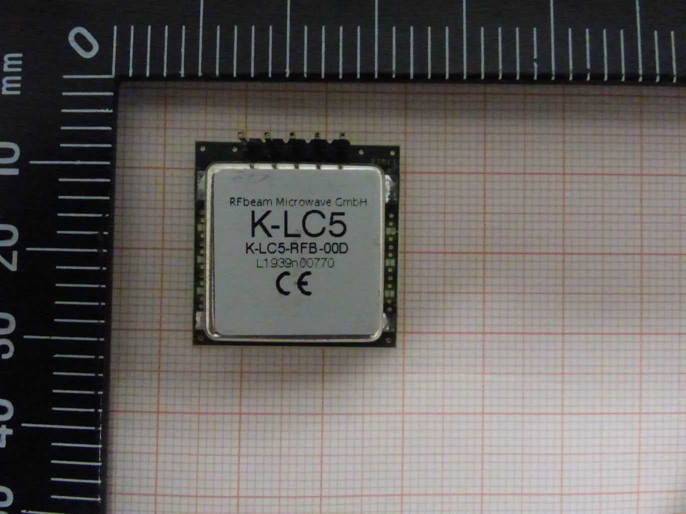
2ASYV-K-LC5
Apr 18, 202124GHz analog radar transceiver
Equipment Class
DXT - Part 15 Low Power Transceiver, Rx Verified